Page 4942 of 6020

8A-4 ELECTRICAL-BODY AND CHASSIS
GENERAL INFORMATION
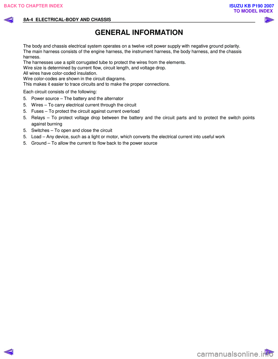
The body and chassis electrical system operates on a twelve volt power supply with negative ground polarity.
The main harness consists of the engine harness, the instrument harness, the body harness, and the chassis
harness.
The harnesses use a split corrugated tube to protect the wires from the elements.
W ire size is determined by current flow, circuit length, and voltage drop.
All wires have color-coded insulation.
W ire color-codes are shown in the circuit diagrams.
This makes it easier to trace circuits and to make the proper connections.
Each circuit consists of the following:
5. Power source – The battery and the alternator
5. W ires – To carry electrical current through the circuit
5. Fuses – To protect the circuit against current overload
5. Relays – To protect voltage drop between the battery and the circuit parts and to protect the switch points against burning
5. Switches – To open and close the circuit
5. Load – Any device, such as a light or motor, which converts the electrical current into useful work
5. Ground – To allow the current to flow back to the power source
BACK TO CHAPTER INDEX TO MODEL INDEXISUZU KB P190 2007
Page 5593 of 6020

Cruise Control – HFV6 Page 8C–15
Step Action Yes No
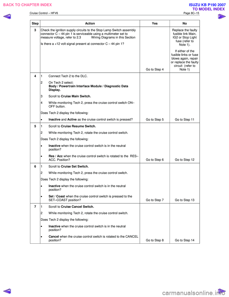
3 Check the ignition supply circuits to the Stop Lamp Switch assembly
connector C – 44 pin 1 is serviceable using a multimeter set to
measure voltage, refer to 2.3 W iring Diagrams in this Section
Is there a +12 volt signal present at connector C – 44 pin 1?
Go to Step 4 Replace the faulty
fusible link Main,
IG2 or Stop Light fuse (refer to Note 1).
If either of the
fusible links or fuse blows again, repair
or replace the faulty circuit (refer to
Note 1)
4 1 Connect Tech 2 to the DLC.
2 On Tech 2 select: Body / Powertrain Interface Module / Diagnostic Data
Display.
3 Scroll to Cruise Main Switch.
4 W hile monitoring Tech 2, press the cruise control switch ON– OFF button.
Does Tech 2 display the following:
• Inactive and Active as the cruise control switch is pressed?
Go to Step 5 Go to Step 11
5 1 Scroll to Cruise Resume Switch.
2 While monitoring Tech 2, rotate the cruise control switch.
Does Tech 2 display the following:
• Inactive when the cruise control switch is in the neutral
position?
• Res / Acc when the cruise control switch is rotated to the RES–
ACC. Position? Go to Step 6 Go to Step 12
6
1 Scroll to Cruise Set Switch.
2 W hile monitoring Tech 2, press the cruise control switch.
Does Tech 2 display the following:
• Inactive when the cruise control switch is in the neutral
position?
• Set / Coast when the cruise control switch is pressed to the
SET–COAST position? Go to Step 7 Go to Step 13
7 1 Scroll to Cruise Cancel Switch.
2 While monitoring Tech 2, rotate the cruise control switch.
Does Tech 2 display the following:
• Inactive when the cruise control switch is in the neutral
position?
• Cancel when the cruise control switch is rotated to the CANCEL
position? Go to Step 8 Go to Step 14
BACK TO CHAPTER INDEX
TO MODEL INDEXISUZU KB P190 2007
Page 5597 of 6020

Cruise Control – HFV6 Page 8C–19
Step Action Yes No
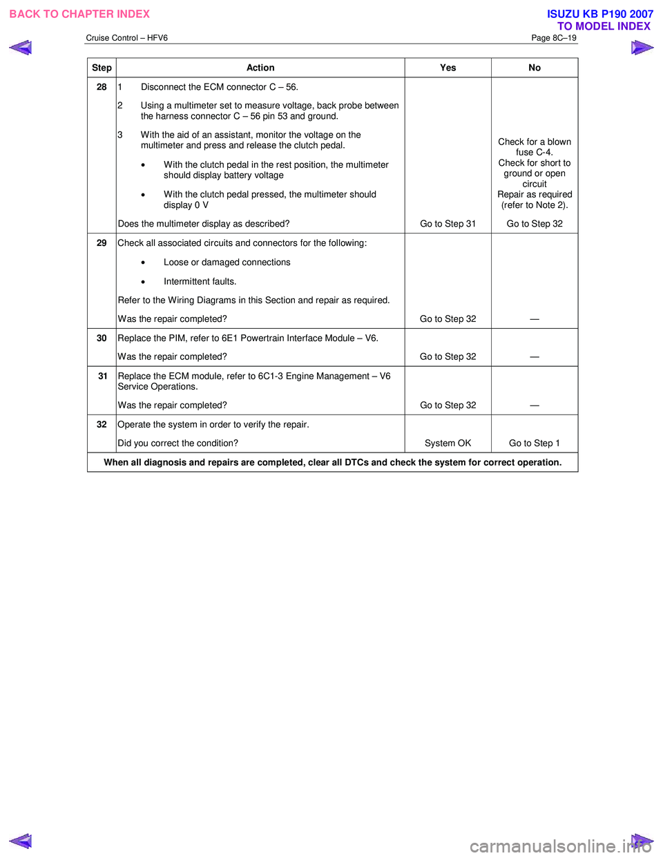
28 1 Disconnect the ECM connector C – 56.
2 Using a multimeter set to measure voltage, back probe between the harness connector C – 56 pin 53 and ground.
3 W ith the aid of an assistant, monitor the voltage on the multimeter and press and release the clutch pedal.
• With the clutch pedal in the rest position, the multimeter
should display battery voltage
• W ith the clutch pedal pressed, the multimeter should
display 0 V
Does the multimeter display as described? Go to Step 31 Check for a blown
fuse C-4.
Check for short to ground or open circuit
Repair as required (refer to Note 2).
Go to Step 32
29 Check all associated circuits and connectors for the following:
• Loose or damaged connections
• Intermittent faults.
Refer to the Wiring Diagrams in this Section and repair as required.
W as the repair completed? Go to Step 32 —
30 Replace the PIM, refer to 6E1 Powertrain Interface Module – V6.
W as the repair completed? Go to Step 32 —
31 Replace the ECM module, refer to 6C1-3 Engine Management – V6
Service Operations.
W as the repair completed? Go to Step 32 —
32 Operate the system in order to verify the repair.
Did you correct the condition? System OK Go to Step 1
When all diagnosis and repairs are completed, clear all DTCs and check the system for correct operation.
BACK TO CHAPTER INDEX
TO MODEL INDEXISUZU KB P190 2007