2007 ISUZU KB P190 diagnostic menu
[x] Cancel search: diagnostic menuPage 5878 of 6020
IMMOBILIZER CONTROL SYSTEM (4JK1/4JJ1/HFV6) 11A-27
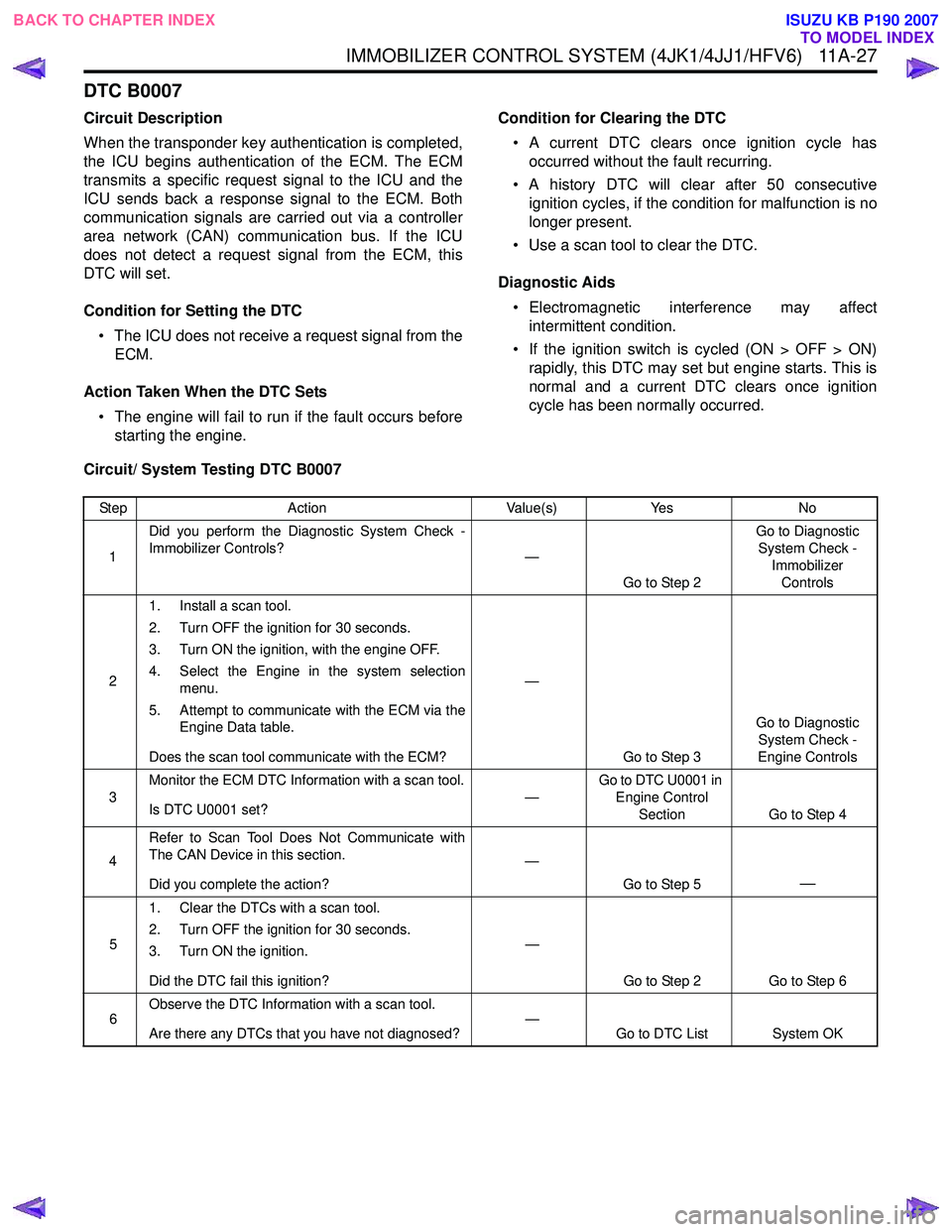
DTC B0007
Circuit Description
When the transponder key authentication is completed,
the ICU begins authentication of the ECM. The ECM
transmits a specific request signal to the ICU and the
ICU sends back a response signal to the ECM. Both
communication signals are carried out via a controller
area network (CAN) communication bus. If the ICU
does not detect a request signal from the ECM, this
DTC will set.
Condition for Setting the DTC • The ICU does not receive a request signal from the ECM.
Action Taken When the DTC Sets • The engine will fail to run if the fault occurs before starting the engine. Condition for Clearing the DTC
• A current DTC clears once ignition cycle has occurred without the fault recurring.
• A history DTC will clear after 50 consecutive ignition cycles, if the condition for malfunction is no
longer present.
• Use a scan tool to clear the DTC.
Diagnostic Aids • Electromagnetic interference may affect intermittent condition.
• If the ignition switch is cycled (ON > OFF > ON) rapidly, this DTC may set but engine starts. This is
normal and a current DTC clears once ignition
cycle has been normally occurred.
Circuit/ System Testing DTC B0007
Step Action Value(s)Yes No
1 Did you perform the Diagnostic System Check -
Immobilizer Controls? —
Go to Step 2 Go to Diagnostic
System Check - Immobilizer Controls
2 1. Install a scan tool.
2. Turn OFF the ignition for 30 seconds.
3. Turn ON the ignition, with the engine OFF.
4. Select the Engine in the system selection menu.
5. Attempt to communicate with the ECM via the Engine Data table.
Does the scan tool communicate with the ECM? —
Go to Step 3 Go to Diagnostic
System Check -
Engine Controls
3 Monitor the ECM DTC Information with a scan tool.
Is DTC U0001 set? —Go to DTC U0001 in
Engine Control
Section Go to Step 4
4 Refer to Scan Tool Does Not Communicate with
The CAN Device in this section.
Did you complete the action? —
Go to Step 5
—
51. Clear the DTCs with a scan tool.
2. Turn OFF the ignition for 30 seconds.
3. Turn ON the ignition.
Did the DTC fail this ignition? —
Go to Step 2 Go to Step 6
6 Observe the DTC Information with a scan tool.
Are there any DTCs that you have not diagnosed? —
Go to DTC List System OK
BACK TO CHAPTER INDEX
TO MODEL INDEX
ISUZU KB P190 2007
Page 5886 of 6020
IMMOBILIZER CONTROL SYSTEM (4JK1/4JJ1/HFV6) 11A-35
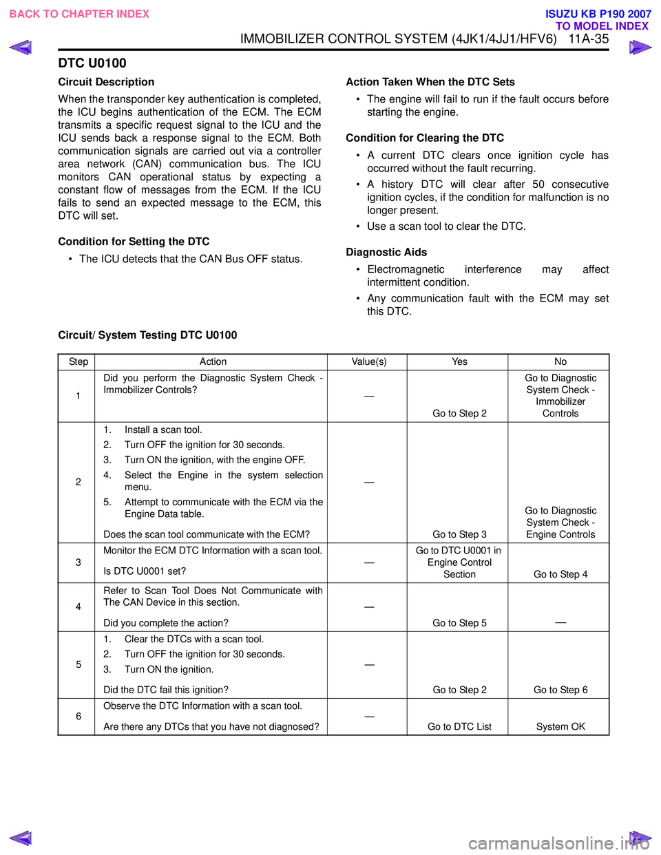
DTC U0100
Circuit Description
When the transponder key authentication is completed,
the ICU begins authentication of the ECM. The ECM
transmits a specific request signal to the ICU and the
ICU sends back a response signal to the ECM. Both
communication signals are carried out via a controller
area network (CAN) communication bus. The ICU
monitors CAN operational status by expecting a
constant flow of messages from the ECM. If the ICU
fails to send an expected message to the ECM, this
DTC will set.
Condition for Setting the DTC • The ICU detects that the CAN Bus OFF status. Action Taken When the DTC Sets
• The engine will fail to run if the fault occurs before starting the engine.
Condition for Clearing the DTC • A current DTC clears once ignition cycle has occurred without the fault recurring.
• A history DTC will clear after 50 consecutive ignition cycles, if the condition for malfunction is no
longer present.
• Use a scan tool to clear the DTC.
Diagnostic Aids • Electromagnetic interference may affect intermittent condition.
• Any communication fault with the ECM may set this DTC.
Circuit/ System Testing DTC U0100
Step Action Value(s)Yes No
1 Did you perform the Diagnostic System Check -
Immobilizer Controls? —
Go to Step 2 Go to Diagnostic
System Check - Immobilizer
Controls
2 1. Install a scan tool.
2. Turn OFF the ignition for 30 seconds.
3. Turn ON the ignition, with the engine OFF.
4. Select the Engine in the system selection menu.
5. Attempt to communicate with the ECM via the Engine Data table.
Does the scan tool communicate with the ECM? —
Go to Step 3 Go to Diagnostic
System Check -
Engine Controls
3 Monitor the ECM DTC Information with a scan tool.
Is DTC U0001 set? —Go to DTC U0001 in
Engine Control Section Go to Step 4
4 Refer to Scan Tool Does Not Communicate with
The CAN Device in this section.
Did you complete the action? —
Go to Step 5
—
51. Clear the DTCs with a scan tool.
2. Turn OFF the ignition for 30 seconds.
3. Turn ON the ignition.
Did the DTC fail this ignition? —
Go to Step 2 Go to Step 6
6 Observe the DTC Information with a scan tool.
Are there any DTCs that you have not diagnosed? —
Go to DTC List System OK
BACK TO CHAPTER INDEX
TO MODEL INDEX
ISUZU KB P190 2007
Page 5899 of 6020
IMMOBILIZER SYSTEM (C24SE, 4JA1-T) 11A-1
IMMOBILIZER SYSTEM
(C24SE, 4JA1-T)
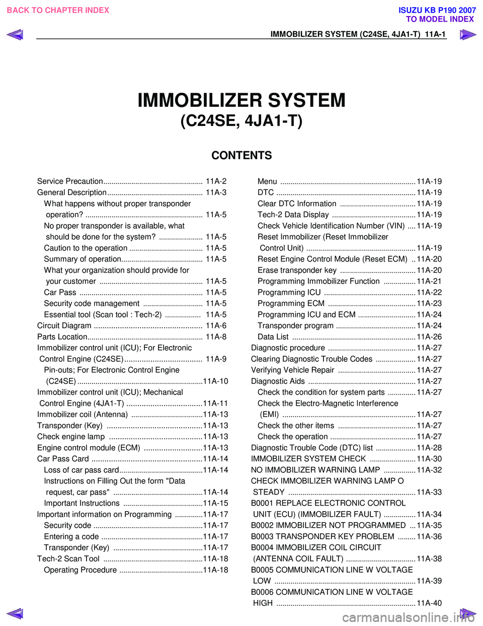
CONTENTS
Service Precaution .................................................. 11A-2
General Description ................................................ 11A-3
W hat happens without proper transponder
operation? ........................................................... 11A-5
No proper transponder is available, what
should be done for the system? ...................... 11A-5
Caution to the operation ..................................... 11A-5
Summary of operation ......................................... 11A-5
W hat your organization should provide for
your customer .................................................... 11A-5
Car Pass .............................................................. 11A-5
Security code management .............................. 11A-5
Essential tool (Scan tool : Tech-2) .................. 11A-5
Circuit Diagram .................................................. 11A-6
Parts Location .......................................................... 11A-8
Immobilizer control unit (ICU); For Electronic
Control Engine (C24SE) .................................... 11A-9
Pin-outs; For Electronic Control Engine
(C24SE) ............................................................... 11A-10
Immobilizer control unit (ICU); Mechanical
Control Engine (4JA1-T) ...................................11A-11
Immobilizer coil (Antenna) ....................................11A-13
Transponder (Key) ............................................11A-13
Check engine lamp ...........................................11A-13
Engine control module (ECM) ...........................11A-13
Car Pass Card ...................................................11A-14 Loss of car pass card .......................................... 11A-14
Instructions on Filling Out the form "Data
request, car pass" ............................................. 11A-14
Important Instructions ........................................ 11A-15
lmportant information on Programming ..............11A-17
Security code ....................................................... 11A-17
Entering a code ................................................... 11A-17
Transponder (Key) ............................................. 11A-17
Tech-2 Scan Tool .................................................. 11A-18
Operating Procedure .......................................... 11A-18
Menu .................................................................... 11A-19
DTC ...................................................................... 11A-19
Clear DTC Information ......................................11A-19
Tech-2 Data Display .......................................... 11A-19
Check Vehicle Identification Number (VIN) ....11A-19
Reset Immobilizer (Reset Immobilizer
Control Unit) ....................................................... 11A-19
Reset Engine Control Module (Reset ECM) ..11A-20
Erase transponder key ......................................11A-20
Programming Immobilizer Function ................11A-21
Programming ICU .............................................. 11A-22
Programming ECM ............................................ 11A-23
Programming ICU and ECM .............................11A-24
Transponder program ........................................ 11A-24
Data List .............................................................. 11A-26
Diagnostic procedure ............................................ 11A-27
Clearing Diagnostic Trouble Codes ....................11A-27
Verifying Vehicle Repair .......................................11A-27
Diagnostic Aids ...................................................... 11A-27
Check the condition for system parts ..............11A-27
Check the Electro-Magnetic Interference
(EMI) ................................................................... 11A-27
Check the other items .......................................11A-27
Check the operation ........................................... 11A-27
Diagnostic Trouble Code (DTC) list ....................11A-28
IMMOBILIZER SYSTEM CHECK .......................11A-30
NO IMMOBILIZER W ARNING LAMP ................11A-32
CHECK IMMOBILIZER W ARNING LAMP O
STEADY ................................................................ 11A-33
B0001 REPLACE ELECTRONIC CONTROL
UNIT (ECU) (IMMOBILIZER FAULT) ................11A-34
B0002 IMMOBILIZER NOT PROGRAMMED ...11A-35
B0003 TRANSPONDER KEY PROBLEM .........11A-36
B0004 IMMOBILIZER COIL CIRCUIT
(ANTENNA COIL FAULT) ...................................11A-38
B0005 COMMUNICATION LINE W VOLTAGE
LOW ....................................................................... 11A-39
B0006 COMMUNICATION LINE W VOLTAGE
HIGH ...................................................................... 11A-40
BACK TO CHAPTER INDEX
TO MODEL INDEX
ISUZU KB P190 2007
Page 5917 of 6020
IMMOBILIZER SYSTEM (C24SE, 4JA1-T) 11A-19
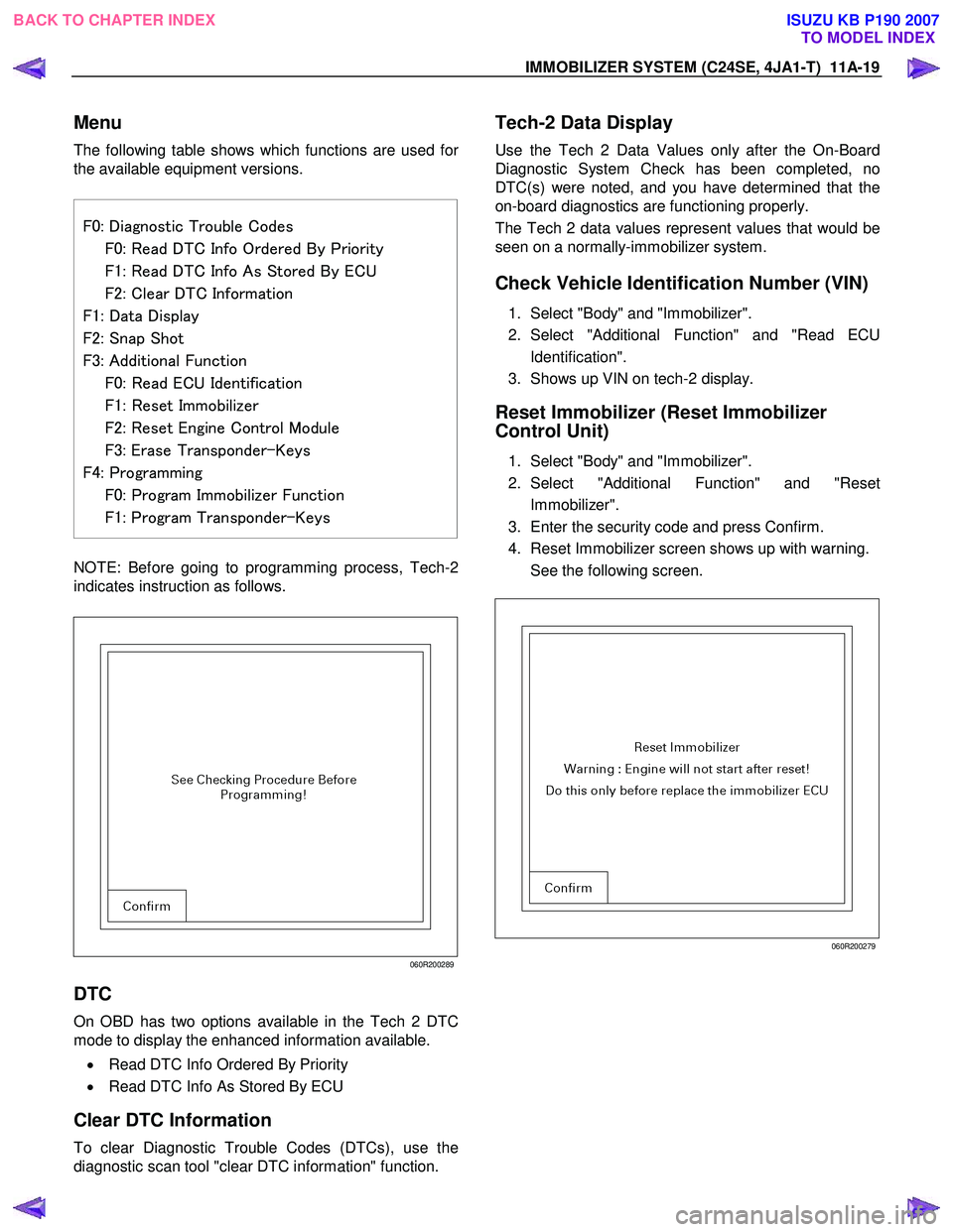
Menu
The following table shows which functions are used for
the available equipment versions.
F0: Diagnostic Trouble Codes
F0: Read DTC Info Ordered By Priority
F1: Read DTC Info As Stored By ECU
F2: Clear DTC Information F1: Data Display
F2: Snap Shot
F3: Additional Function
F0: Read ECU Identification
F1: Reset Immobilizer
F2: Reset Engine Control Module
F3: Erase Transponder-Keys F4: Programming
F0: Program Immobilizer Function
F1: Program Transponder-Keys
NOTE: Before going to programming process, Tech-2
indicates instruction as follows.
060R200289
DTC
On OBD has two options available in the Tech 2 DTC
mode to display the enhanced information available.
• Read DTC Info Ordered By Priority
• Read DTC Info As Stored By ECU
Clear DTC Information
To clear Diagnostic Trouble Codes (DTCs), use the
diagnostic scan tool "clear DTC information" function.
Tech-2 Data Display
Use the Tech 2 Data Values only after the On-Board
Diagnostic System Check has been completed, no
DTC(s) were noted, and you have determined that the
on-board diagnostics are functioning properly.
The Tech 2 data values represent values that would be
seen on a normally-immobilizer system.
Check Vehicle Identification Number (VIN)
1. Select "Body" and "Immobilizer".
2. Select "Additional Function" and "Read ECU
Identification".
3. Shows up VIN on tech-2 display.
Reset Immobilizer (Reset Immobilizer
Control Unit)
1. Select "Body" and "Immobilizer".
2. Select "Additional Function" and "Reset
Immobilizer".
3. Enter the security code and press Confirm.
4. Reset Immobilizer screen shows up with warning.
See the following screen.
060R200279
BACK TO CHAPTER INDEX TO MODEL INDEX
ISUZU KB P190 2007
Page 5955 of 6020
ANTITHEFT SYSTEM 11B-1
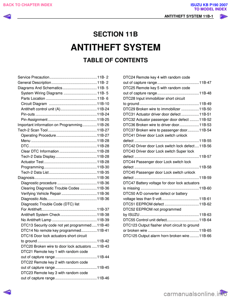
SECTION 11B
ANTITHEFT SYSTEM
TABLE OF CONTENTS
Service Precaution .................................................. 11B- 2
General Description ................................................ 11B- 2
Diagrams And Schematics ................................. 11B- 5 System W iring Diagrams ................................ 11B- 5
Parts Location ................................................. 11B- 6
Circuit Diagram ..............................................11B-10
Antitheft control unit (A) ...................................11B-24
Pin-outs ...........................................................11B-24
Pin-Assignment ...............................................11B-25
lmportant information on Programming..............11B-26
Tech-2 Scan Tool ...............................................11B-27 Operating Procedure .......................................11B-27
Menu ...............................................................11B-28
DTC .................................................................11B-28
Clear DTC Information ....................................11B-28
Tech-2 Data Display........................................11B-28
Actuator Test ...................................................11B-28
Programming...................................................11B-30
Tech-2 Data List ..............................................11B-35
Diagnosis............................................................11B-36 Diagnostic procedure ......................................11B-36
Clearing Diagnostic Trouble Codes ................11B-36
Verifying Vehicle Repair ..................................11B-36
Diagnostic Aids................................................11B-36
Diagnostic Trouble Code (DTC) list
For Antitheft.....................................................11B-37
Antitheft System Check ...................................11B-38
No Antitheft Lamp ...........................................11B-39
DTC13 Security code not yet programmed .....11B-40
DTC14 No remote key programmed ...............11B-41
DTC16 Door lock actuators short circuit
to ground .........................................................11B-42
DTC20 Broken wire to door lock actuators .....11B-43
DTC21 Remote key 1 with random code
out of capture range ........................................11B-44
DTC22 Remote key 2 with random code
out of capture range ........................................11B-45
DTC23 Remote key 3 with random code
out of capture range ........................................11B-46
DTC24 Remote key 4 with random code
out of capture range ........................................ 11B-47
DTC25 Remote key 5 with random code
out of capture range ........................................ 11B-48
DTC28 Input immobilizer short circuit
to ground ......................................................... 11B-49
DTC29 Broken wire to immobilizer ................. 11B-50
DTC31 Actuator driver door defect ................. 11B-51
DTC32 Actuator passenger door defect ......... 11B-52
DTC36 Broken wire to driver door................... 11B-53
DTC37 Broken wire to passenger door........... 11B-54
DTC41 Driver door Lock switch unlock
defect .............................................................. 11B-55
DTC42 Driver door Lock switch lock defect .... 11B-56
DTC43 Driver door Lock switch Super lock
defect .............................................................. 11B-57
DTC44 Passenger door Lock switch lock
defect .............................................................. 11B-58
DTC45 Passenger door Lock switch unlock
defect .............................................................. 11B-59
DTC47 Battery voltage for door lock actuators
is missing ........................................................ 11B-60
DTC50 A/D converter defect or battery
voltage less than 9 volt.................................... 11B-61
DTC51 EEPROM defect ................................. 11B-62
DTC52 EEPROM not programmed
by ISUZU ......................................................... 11B-63
DTC55 Control unit defect............................... 11B-64
DTC123 Output flasher short circuit to ground
or broken wire ................................................. 11B-65
DTC125 Output alarm horn broken wire ......... 11B-66
BACK TO CHAPTER INDEX TO MODEL INDEX
ISUZU KB P190 2007
Page 5982 of 6020
11B-28 ANTITHEFT SYSTEM
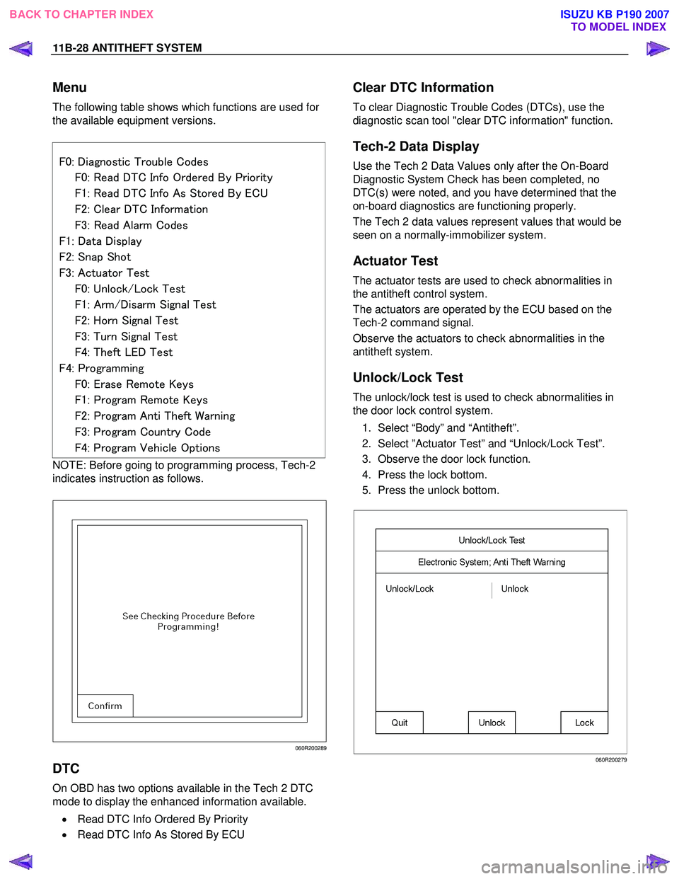
Menu
The following table shows which functions are used for
the available equipment versions.
F0: Diagnostic Trouble Codes
F0: Read DTC Info Ordered By Priority
F1: Read DTC Info As Stored By ECU
F2: Clear DTC Information
F3: Read Alarm Codes
F1: Data Display
F2: Snap Shot
F3: Actuator Test
F0: Unlock/Lock Test
F1: Arm/Disarm Signal Test
F2: Horn Signal Test
F3: Turn Signal Test
F4: Theft LED Test
F4: Programming
F0: Erase Remote Keys
F1: Program Remote Keys
F2: Program Anti Theft Warning
F3: Program Country Code
F4: Program Vehicle Options
NOTE: Before going to programming process, Tech-2
indicates instruction as follows.
060R200289
DTC
On OBD has two options available in the Tech 2 DTC
mode to display the enhanced information available.
• Read DTC Info Ordered By Priority
• Read DTC Info As Stored By ECU
Clear DTC Information
To clear Diagnostic Trouble Codes (DTCs), use the
diagnostic scan tool "clear DTC information" function.
Tech-2 Data Display
Use the Tech 2 Data Values only after the On-Board
Diagnostic System Check has been completed, no
DTC(s) were noted, and you have determined that the
on-board diagnostics are functioning properly.
The Tech 2 data values represent values that would be
seen on a normally-immobilizer system.
Actuator Test
The actuator tests are used to check abnormalities in
the antitheft control system.
The actuators are operated by the ECU based on the
Tech-2 command signal.
Observe the actuators to check abnormalities in the
antitheft system.
Unlock/Lock Test
The unlock/lock test is used to check abnormalities in
the door lock control system.
1. Select “Body” and “Antitheft”.
2. Select ”Actuator Test” and “Unlock/Lock Test”.
3. Observe the door lock function.
4. Press the lock bottom.
5. Press the unlock bottom.
060R200279
BACK TO CHAPTER INDEX TO MODEL INDEX
ISUZU KB P190 2007