Page 1586 of 6020
FUEL SYSTEM (4JK1/4JJ1) 6C-45
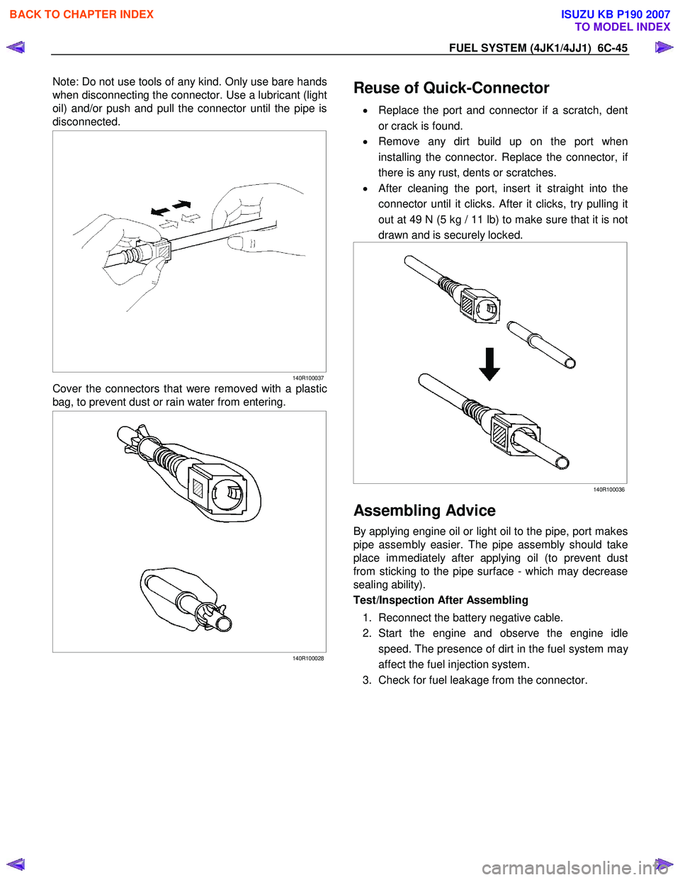
Note: Do not use tools of any kind. Only use bare hands
when disconnecting the connector. Use a lubricant (light
oil) and/or push and pull the connector until the pipe is
disconnected.
140R100037
Cover the connectors that were removed with a plastic
bag, to prevent dust or rain water from entering.
140R100028
Reuse of Quick-Connector
•
Replace the port and connector if a scratch, dent
or crack is found.
• Remove any dirt build up on the port when
installing the connector. Replace the connector, i
f
there is any rust, dents or scratches.
• After cleaning the port, insert it straight into the
connector until it clicks. After it clicks, try pulling it
out at 49 N (5 kg / 11 lb) to make sure that it is not
drawn and is securely locked.
140R100036
Assembling Advice
By applying engine oil or light oil to the pipe, port makes
pipe assembly easier. The pipe assembly should take
place immediately after applying oil (to prevent dust
from sticking to the pipe surface - which may decrease
sealing ability).
Test/Inspection After Assembling
1. Reconnect the battery negative cable.
2. Start the engine and observe the engine idle speed. The presence of dirt in the fuel system ma
y
affect the fuel injection system.
3. Check for fuel leakage from the connector.
BACK TO CHAPTER INDEX
TO MODEL INDEX
ISUZU KB P190 2007
Page 1589 of 6020
ENGINE ELECTRICAL (4JK1/4JJ1) 6D-1
SECTION 6D
ENGINE ELECTRICAL
TABLE OF CONTENTS
Charging System ................................................ 6D-2
Servicing Cautions .......................................... 6D-2
Important Generator Components and
Function.......................................................... 6D-2
Troubleshooting .............................................. 6D-5
Diagnosis......................................................... 6D-7
Specifications .................................................. 6D-8
Unit Se rv ic ing (4 JJ 1) ....................................... .... ..6D -9
Disassembly .................................................... 6D-10
Inspection and Repair ..................................... 6D-11 Rotor Assembly ........................................... 6D-11
Stator Coil .................................................... 6D-12
Brushes ....................................................... 6D-12
Rectifier ....................................................... 6D-13
Regulator Assembly..................................... 6D-13
Measuring Procedure .................................. 6D-13
Reassembly..................................................... 6D-14
Final Assembly ................................................ 6D-14
Starter Motor ...................................................... 6D-15 Starting Circuit Diagram .................................. 6D-15
Removal and Installation ................................. 6D-15 Important Operations – Removal................. 6D-15
Important Operations – Installation.............. 6D-15
Disassembly .................................................... 6D-16 Disassembly Steps ...................................... 6D-16
Important Operations ................................... 6D-17
Inspection and Repair ..................................... 6D-20 Armature ...................................................... 6D-20
Yoke............................................................. 6D-21
Brush and Brush Holder .............................. 6D-22
Overrunning Clutch...................................... 6D-22
Bearing ........................................................ 6D-23
Reassembly..................................................... 6D-24 Reassembly Steps ....................................... 6D-24
Important Operations ................................... 6D-25
Inspection After Assembly ........................... 6D-26
Magnetic Switch .............................................. 6D-27
Torque Specifications...................................... 6D-28
Pre-Heating System ........................................... 6D-29 Inspection and Repair ..................................... 6D-29 Visual Check................................................ 6D-29
Glow Relay .................................................. 6D-29
Glow Plug .................................................... 6D-29
BACK TO CHAPTER INDEX
TO MODEL INDEX
ISUZU KB P190 2007
Page 1590 of 6020
6D-2 ENGINE ELECTRICAL (4JK1/4JJ1)
Charging System
Servicing Cautions
• Battery polarity is important. If the battery cables
are reversed, the generator diodes will be
destroyed.
• Do not remove the battery cables or the charging
circuit wiring when the engine is running.
• Confirm that the terminal wires are connected to
the proper terminals by checking the terminal
numbers (the number on the terminal wire and the
terminal must be the same).
• Disconnect the battery negative cable (-) before
inspecting the generator.
• Do not open or close the battery relay switch when
the engine is running.
• Disconnect the battery negative cable (-) when
using external equipment (Quick-Charge) to
charge the battery.
• W hen steam cleaning or washing the engine, do
not allow steam or water to come in direct contact
with the battery and other electrical system
components.
• Be sure to read the item on belt tension
adjustment before beginning the procedure.
Important Generator Components
and Function
• The generator used on 4JK1 engine cannot be
disassembled.
• The generator uses a built-in solid-state IC voltage
regulator. The regulator and other important
components together with their connections are
shown in the illustration.
• The voltage regulator is installed to the rear cove
r
assembly of the generator together with the brush
holder and the rectifier. The generator requires no
additional voltage regulation.
• 9 diodes are connected to the stator coil to convert
AC to DC. The DC voltage is delivered to the
generator output terminal.
BACK TO CHAPTER INDEX
TO MODEL INDEX
ISUZU KB P190 2007
Page 1595 of 6020
ENGINE ELECTRICAL (4JK1/4JJ1) 6D-7
Diagnosis
On-vehicle Inspection
The charging system warning light tells the vehicle
operator of possible problems with the system.
W hen the ignition switch is moved to the ON position,
the light turns on. The light turns off immediately afte
r
the engine is started. If the light turns on during engine
operation, there is a problem with the charging system.
Perform the checks described below.
1. Check the belt (broken or loose).
2. Check the harness connectors (loose o
r
disconnected).
3. W ith the engine off, turn the ignition switch to the ON position. If the warning lamp does not light,
remove the harness connector from the generator.
Ground the connector IG terminal. The lamp
should light. If it does not, the bulb is burned out.
Replace the bulb.
4. Start the engine. If the warning lamp remains on, the generator must be repaired or replaced.
BACK TO CHAPTER INDEX
TO MODEL INDEX
ISUZU KB P190 2007
Page 1599 of 6020
ENGINE ELECTRICAL (4JK1/4JJ1) 6D-11
13.Remove the stator.
066RS030
14.Remove the bolts securing the regulator, the
rectifier, and the brush holder. Separate the parts.
066RW 025
Inspection and Repair
Repair or replace any parts found to be excessively
worn or damaged during the inspection procedure.
Rotor Assembly
1. Check for dirty or rough slip ring surfaces. Remove
dirt from the surfaces with a clean rag. Use No.
500 or No. 600 sandpaper to smooth the surfaces.
2. Measure the slip ring diameters. Replace the slip ring if the diameter is less than the specified limit.
Slip ring diameter mm (in)
Standard 27 (1.063)
Limit 26 (1.024)
066RS032
3. Measure the electrical resistance between the slip
rings. If the resistance is greater than the specified
limit (open circuit), repair is required.
Slip ring resistance Ω
Less than 3.75
066RS033
BACK TO CHAPTER INDEX
TO MODEL INDEX
ISUZU KB P190 2007
Page 1600 of 6020
6D-12 ENGINE ELECTRICAL (4JK1/4JJ1)
4. Check for conductivity between the slip rings and
the rotor core. If there is continuity, the roto
r
assembly must be replaced.
066RS017
Stator Coil
1. Measure the stator coil resistance. If the
resistance is less than the specified value, the
stator coil must be replaced.
Stator coil resistance
0.07Ω at 20 °C (68 °F)
066RS034
2. Measure the resistance between the stator coil
and the stator core. If the resistance is less than
the specified value, the stator coil must be
replaced.
Stator coil/core resistance MΩ
1
066RS035
Brushes
Measure the brush height. If the height is less than the
specified limit, the brushes must be replaced.
Brush height mm (in)
Standard 18 (0.709)
Limit 5.5 (0.217)
066RW 024
BACK TO CHAPTER INDEX
TO MODEL INDEX
ISUZU KB P190 2007
Page 1601 of 6020
ENGINE ELECTRICAL (4JK1/4JJ1) 6D-13
Rectifier
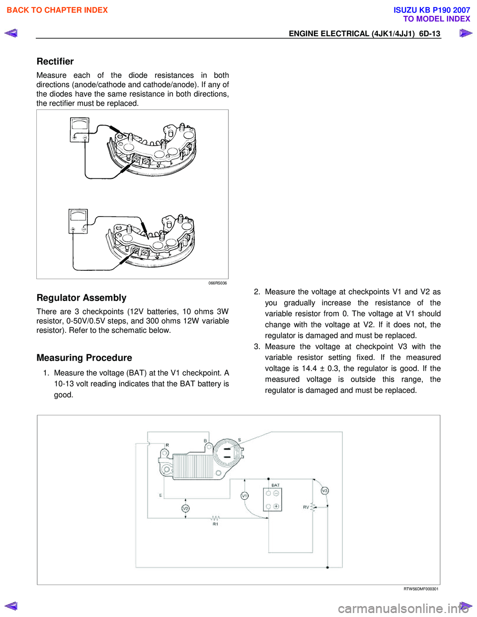
Measure each of the diode resistances in both
directions (anode/cathode and cathode/anode). If any o
f
the diodes have the same resistance in both directions,
the rectifier must be replaced.
066RS036
Regulator Assembly
There are 3 checkpoints (12V batteries, 10 ohms 3W
resistor, 0-50V/0.5V steps, and 300 ohms 12W variable
resistor). Refer to the schematic below.
Measuring Procedure
1. Measure the voltage (BAT) at the V1 checkpoint. A
10-13 volt reading indicates that the BAT battery is
good.
2. Measure the voltage at checkpoints V1 and V2 as
you gradually increase the resistance of the
variable resistor from 0. The voltage at V1 should
change with the voltage at V2. If it does not, the
regulator is damaged and must be replaced.
3. Measure the voltage at checkpoint V3 with the variable resistor setting fixed. If the measured
voltage is 14.4 ± 0.3, the regulator is good. If the
measured voltage is outside this range, the
regulator is damaged and must be replaced.
RTW 56DMF000301
BACK TO CHAPTER INDEX
TO MODEL INDEX
ISUZU KB P190 2007
Page 1608 of 6020
6D-20 ENGINE ELECTRICAL (4JK1/4JJ1)
Inspection and Repair
Make the necessary adjustments, repairs, and part
replacement if excessive wear or damage is discovered
during inspection.
Armature
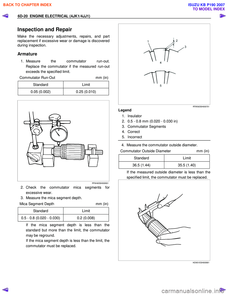
1. Measure the commutator run-out.
Replace the commutator if the measured run-out
exceeds the specified limit.
Commutator Run-Out mm (in)
Standard Limit
0.05 (0.002) 0.25 (0.010)
RTW 46DSH003501
2. Check the commutator mica segments for
excessive wear.
3. Measure the mica segment depth.
Mica Segment Depth mm (in)
Standard Limit
0.5 - 0.8 (0.020 - 0.030) 0.2 (0.008)
If the mica segment depth is less than the standard but more than the limit, the commutato
r
may be reground.
If the mica segment depth is less than the limit, the commutator must be replaced.
RTW 56DSH000701
Legend
1. Insulator
2. 0.5 - 0.8 mm (0.020 - 0.030 in)
3. Commutator Segments
4. Correct
5. Incorrect
4. Measure the commutator outside diameter.
Commutator Outside Diameter mm (in)
Standard Limit
36.5 (1.44) 35.5 (1.40)
If the measured outside diameter is less than the
specified limit, the commutator must be replaced.
HCW 51ESH000901
BACK TO CHAPTER INDEX
TO MODEL INDEX
ISUZU KB P190 2007