2007 ISUZU KB P190 FLASH CODE
[x] Cancel search: FLASH CODEPage 4371 of 6020
TRANSMISSION CONTROL SYSTEM (JR405E) 7A2-87
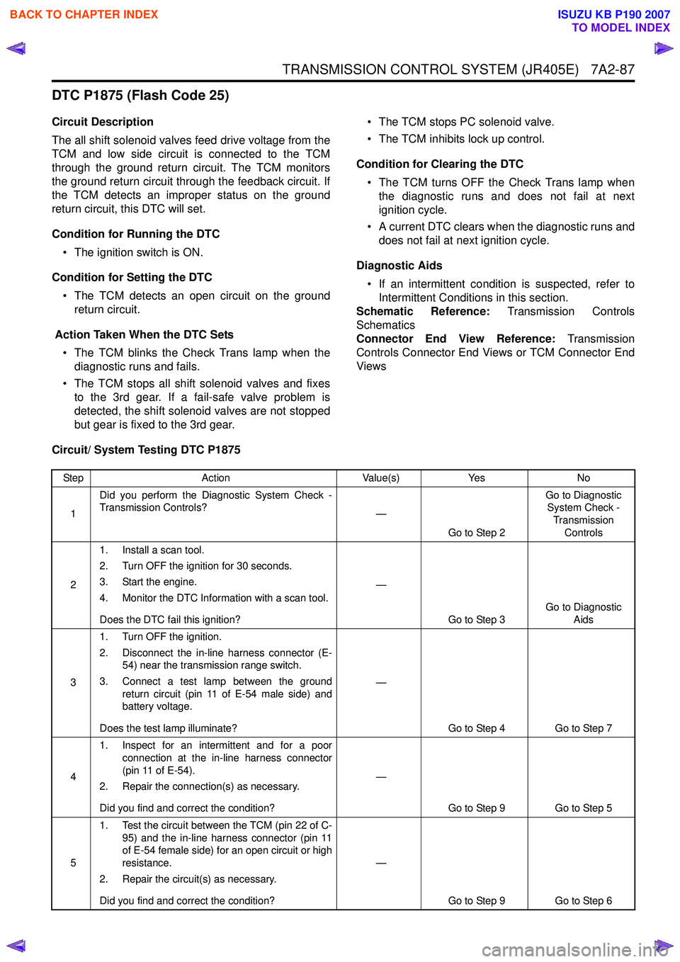
DTC P1875 (Flash Code 25)
Circuit Description
The all shift solenoid valves feed drive voltage from the
TCM and low side circuit is connected to the TCM
through the ground return circuit. The TCM monitors
the ground return circuit through the feedback circuit. If
the TCM detects an improper status on the ground
return circuit, this DTC will set.
Condition for Running the DTC • The ignition switch is ON.
Condition for Setting the DTC • The TCM detects an open circuit on the ground return circuit.
Action Taken When the DTC Sets • The TCM blinks the Check Trans lamp when the diagnostic runs and fails.
• The TCM stops all shift solenoid valves and fixes to the 3rd gear. If a fail-safe valve problem is
detected, the shift solenoid valves are not stopped
but gear is fixed to the 3rd gear. • The TCM stops PC solenoid valve.
• The TCM inhibits lock up control.
Condition for Clearing the DTC • The TCM turns OFF the Check Trans lamp when the diagnostic runs and does not fail at next
ignition cycle.
• A current DTC clears when the diagnostic runs and does not fail at next ignition cycle.
Diagnostic Aids • If an intermittent condition is suspected, refer to Intermittent Conditions in this section.
Schematic Reference: Transmission Controls
Schematics
Connector End View Reference: Transmission
Controls Connector End Views or TCM Connector End
Views
Circuit/ System Testing DTC P1875
Step Action Value(s)Yes No
1 Did you perform the Diagnostic System Check -
Transmission Controls? —
Go to Step 2 Go to Diagnostic
System Check -
Transmission Controls
2 1. Install a scan tool.
2. Turn OFF the ignition for 30 seconds.
3. Start the engine.
4. Monitor the DTC Information with a scan tool.
Does the DTC fail this ignition? —
Go to Step 3 Go to Diagnostic
Aids
3 1. Turn OFF the ignition.
2. Disconnect the in-line harness connector (E- 54) near the transmission range switch.
3. Connect a test lamp between the ground return circuit (pin 11 of E-54 male side) and
battery voltage.
Does the test lamp illuminate? —
Go to Step 4 Go to Step 7
4 1. Inspect for an intermittent and for a poor
connection at the in-line harness connector
(pin 11 of E-54).
2. Repair the connection(s) as necessary.
Did you find and correct the condition? —
Go to Step 9 Go to Step 5
5 1. Test the circuit between the TCM (pin 22 of C-
95) and the in-line harness connector (pin 11
of E-54 female side) for an open circuit or high
resistance.
2. Repair the circuit(s) as necessary.
Did you find and correct the condition? —
Go to Step 9 Go to Step 6
BACK TO CHAPTER INDEX
TO MODEL INDEX
ISUZU KB P190 2007
Page 5490 of 6020
8A-552 ELECTRICAL-BODY AND CHASSIS
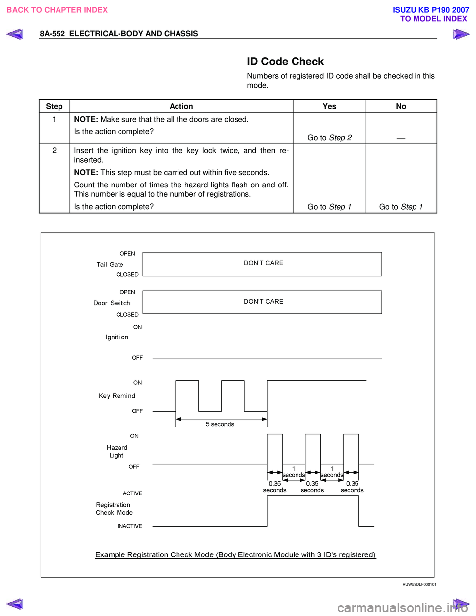
ID Code Check
Numbers of registered ID code shall be checked in this
mode.
Step Action Yes No
1 NOTE: Make sure that the all the doors are closed.
Is the action complete? Go to Step 2
2 Insert the ignition key into the key lock twice, and then re-
inserted.
NOTE: This step must be carried out within five seconds.
Count the number of times the hazard lights flash on and off.
This number is equal to the number of registrations.
Is the action complete? Go to Step 1 Go to Step 1
RUW 59DLF000101
BACK TO CHAPTER INDEX TO MODEL INDEXISUZU KB P190 2007
Page 5649 of 6020
9A-14 SUPPLEMENTAL RESTRAINT SYSTEM
Component Description
SRS Control Unit
WARNING: DURING SERVICE PROCEDURES, BE
VERY CAREFUL WHEN HANDLING A SRS
CONTROL UNIT. NEVER STRIKE OR JAR THE SRS
CONTORL UNIT. NEVER POWER UP THE SRS
WHEN THE SRS CONTROL UNIT IS NOT RIGIDLY
ATTACHED TO THE VEHICLE. ALL SRS CONTROL
UNIT AND MOUNTING BRACKET FASTENERS
MUST BE CAREFULLY TORQUED AND THE
ARROW MUST BE POINTED TOWARD THE FRONT
OF THE VEHICLE TO ENSURE PROPER
OPERATION OF THE SRS. THE SRS CONTROL
UNIT COULD BE ACTIVATED WHEN POWERED
WHILE NOT RIGIDLY ATTACHED TO THE
VEHICLE WHICH COULD CAUSE DEPLOYMENT
AND RESULT IN PERSONAL INJURY.
The SRS control unit is designed to perform the
following functions in the SRS:
1. Energy Reserve — The SRS control unit maintains 30–Volt Loop Reserve (30VLR) energy supply to
provide deployment energy when ignition voltage is
lost in a frontal crash.
2. Frontal Crash Detection — The SRS control unit monitors vehicle velocity changes to detect frontal
crashes which are severe enough to warrant
deployment.
3. Air Bag Deployment — W hen a frontal crash o
f
sufficient force is detected, the SRS control unit
will cause enough current to flow through the ai
r
bag assembly to deploy the air bag.
4. Malfunction Detection — The SRS control unit performs diagnostic monitoring of SRS electrical
components and sets a diagnostic trouble code
when a malfunction is detected.
5. Frontal Crash Recording — The SRS control unit records information regarding SRS status during
frontal crash.
6. Malfunction Diagnosis — The SRS control unit displays SRS diagnostic trouble codes and system
status information through the use of a scan tool.
7. Driver Notification — The SRS control unit warns the vehicle driver of SRS malfunctions b
y
controlling the “SRS” warning lamp.
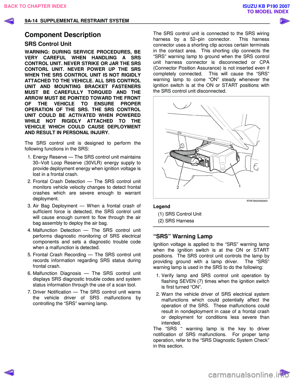
The SRS control unit is connected to the SRS wiring
harness by a 52–pin connector. This harness
connector uses a shorting clip across certain terminals
in the contact area. This shorting clip connects the
“SRS” warning lamp to ground when the SRS control
unit harness connector is disconnected or CP
A
(Connector Position Assurance) is not inserted even i
f
completely connected. This will cause the “SRS”
warning lamp to come “ON” steady whenever the
ignition switch is at the ON or START positions with
the SRS control unit disconnected.
RTW 79ASH000401
Legend
(1) SRS Control Unit
(2) SRS Harness
“SRS” Warning Lamp
Ignition voltage is applied to the “SRS” warning lamp
when the ignition switch is at the ON or START
positions. The SRS control unit controls the lamp b
y
providing ground with a lamp driver. The “SRS”
warning lamp is used in the SRS to do the following:
1. Verify lamp and SRS control unit operation b
y
flashing SEVEN (7) times when the ignition switch
is first turned “ON”.
2. W arn the vehicle driver of SRS electrical system malfunctions which could potentially affect the
operation of the SRS. These malfunctions could
result in nondeployment in case of a frontal crash
or deployment for conditions less severe than
intended.
The “SRS “ warning lamp is the key to drive
r
notification of SRS malfunctions. For proper lamp
operation, refer to the “SRS Diagnostic System Check”
in this section.
BACK TO CHAPTER INDEX TO MODEL INDEXISUZU KB P190 2007
Page 5656 of 6020
SUPPLEMENTAL RESTRAINT SYSTEM 9A-21
On–Vehicle Service
Service Precaution
WARNING: WHEN PERFORMING SERVICE ON OR
AROUND SRS COMPONENTS OR SRS WIRING,
FOLLOW THE PROCEDURES LISTED BELOW TO
TEMPORARILY DISABLE THE SRS. FAILURE TO
FOLLOW PROCEDURES COULD RESULT IN
POSSIBLE AIR BAG DEPLOYMENT, PERSONAL
INJURY OR OTHERWISE UNNECESSARY SRS
REPAIRS.
The SRS control unit in Driver–Passenger SRS can
maintain sufficient voltage to cause a deployment fo
r
up to 15 seconds after the ignition switch is turned
“OFF,” the battery is disconnected, or the fuse
powering the SRS control unit is removed.
Many of the service procedures require removal of the
“SRS” fuse, and disconnection of the air bag assembl
y
from the deployment loop to avoid an accidental
deployment. If the air bag assembly is disconnected
from the deployment loop as noted in the “Disabling
the SRS” procedure that follows, service can begin
immediately without waiting for the 15 second time
period to expire.
Disabling The SRS
Removal
Turn the ignition switch to “LOCK” and remove the
key.
1. Remove the SRS fuse “SRS”, from the side of the driver’s side of the instrument panel fuse block o
r
disconnect the battery.
2. Disconnect the yellow connector at the base of the steering column.
3. Remove the glove box assembly, refer to “Passenger Air Bag Assembly Replacement” in
this manual.
4. Disconnect the yellow connector behind the glove box assembly.
CAUTION: With the “SRS” fuse removed and
ignition switched “ON”, the “SRS” warning lamp
will be “ON”. This is normal operation and does
not indicate an SRS malfunction.
Enabling The SRS
Installation
CAUTION: Never use the air bag assembly from
another vehicle or different model year air bag
assembly.
Use only a new air bag assembly matched to the
TFR/S which is being repaired.
Turn the ignition switch to “LOCK” and remove the
key.
1. Connect the yellow connector passenger air bag assembly.
2. Install the glove box assembly. Refer to “Passenger air bag assembly replacement” in this
manual.
3. Connect the yellow connector at the base of the steering column.
4. Install the “AIR BAG” fuse “SRS” to the side of the driver’s side of the instrument panel fuse block o
r
connect the battery.
Turn the ignition switch to “ON” and verify that the
“SRS” warning lamp flashes seven times and then
turns to “LOCK”. If it does not operate as described,
perform the “SRS Diagnostic System Check” in this
manual.
Handling / Installation / Diagnosis
1. The air bag assembly should not be subjected to temperatures above 65
°C (150°F).
2. The air bag assembly, and SRS control unit, should not be used if they have been dropped from
a height of 100 centimeters (3.28 feet) or more.
3. W hen the SRS control unit is replaced, it must be oriented with the arrow on the sensor pointing
toward the front of the vehicle. It is very important
for the SRS control unit to be located flat on the
mounting surface, parallel to the vehicle datum
line. It is important that the SRS control unit
mounting surface is free of any dirt or other foreign
material.
4. Do not apply power to the SRS unless all components are connected or a diagnostic chart
requests it, as this will set a diagnostic trouble
code.
5. The “SRS Diagnostic System Check” must be the starting point of any SRS diagnostics. The “SRS
Diagnostic System Check” will verify proper “SRS”
warning lamp operation and will lead you to the
correct chart to diagnose any SRS malfunctions.
Bypassing these procedures may result in
extended diagnostic time, incorrect diagnosis, and
incorrect parts replacement.
BACK TO CHAPTER INDEX TO MODEL INDEXISUZU KB P190 2007
Page 5667 of 6020
9A-32 SUPPLEMENTAL RESTRAINT SYSTEM
Service Precautions for SRS
Component Service
CAUTION: When fasteners are removed, always
reinstall them at the same location from which
they were removed. If a fastener needs to be
replaced, use the correct part number fastener fo
r
that application. If the correct part number
fastener is not available, a fastener of equal size
and strength (or stronger) may be used. Fasteners
that are not reused, and those requiring a thread
locking compound will be called out. The correct
torque value must be used when installing
fasteners that require it. If the above conditions
are not followed, parts or system damage could
result.
WARNING: WHEN PERFORMING SERVICE ON OR
AROUND SRS COMPONENTS OR SRS WIRING,
FOLLOW THE PROCEDURES LISTED BELOW TO
TEMPORARILY DISABLE THE SRS. FAILURE TO
FOLLOW PROCEDURES COULD RESULT IN
POSSIBLE AIR BAG DEPLOYMENT, PERSONAL
INJURY OR OTHERWISE UNNEEDED SRS
REPAIRS.
The SRS control unit in the Driver–Passenger SRS
can maintain sufficient voltage to cause a deployment
for up to 15 seconds after the ignition switch is turned
“OFF,” the battery is disconnected, or the fuse
powering the SRS control unit is removed.
Many of the service procedures require removal of the
“SRS” fuse, and disconnection of the air bag assembl
y
from the deployment loop to avoid an accidental
deployment. If the air bag assembly is disconnected
from the deployment loop as noted in the “Disabling
the SRS” procedure that follows, service can begin
immediately without waiting for the 15 second time
period to expire.
Disabling The SRS
Removal
Turn the ignition switch to “OFF” and turn the steering
wheel so that the vehicle's wheels are pointing straight
ahead.
1. Remove the SRS fuse “SRS” from the left dash side lower fuse block or disconnect the battery.
2. Disconnect the yellow connector at the base o
f
steering column.
3. Remove the glove box assembly; Refer to “Passenger air bag assembly replacement” in this
section.
4. Disconnect the passenger air bag assembly yello
w
connector behind the glove box assembly.
CAUTION: With the “SRS” fuse removed and the
ignition switch to “ON,” the “SRS” warning lamp
will be “ON.” This is normal operation and does
not indicate an SRS malfunction.
Enabling The SRS
Installation
Turn the ignition switch to “LOCK” and remove the
key.
1. Connect the yellow connector passenger air bag assembly.
2. Install the glove box assembly. Refer to “Passenger Air Bag Assembly Replacement” in
this section.
3. Connect the yellow connector at the base of the steering column.
4. Install the “AIR BAG” fuse “SRS” to the left dash side lower fuse block or connect the battery.
Turn the ignition switch to “ON” and verify that the
“SRS” warning lamp flashes seven times and then
turns to “LOCK”. If it does not operate as described,
perform the “SRS Diagnostic System Check” in this
section.
Handling / Installation / Diagnosis
1. Air bag assembly should not be subjected to
temperatures above 65 °C (150 °F).
2.
Air bag assembly, and SRS control unit should not
be used if they have been dropped from a height
of 100 centimeters (3.28 feet) or more.
3. W hen a SRS control unit is replaced, it must be oriented with the arrow on the SRS control unit
pointing toward the front of the vehicle. It is ver
y
important for the SRS control unit to be located flat
on the mounting surface, parallel to the vehicle
datum line. It is important that the SRS control unit
mounting surface is free of any dirt or other foreign
material.
4. Do not apply power to the SRS unless all components are connected or a diagnostic chart
requests it, as this will set a diagnostic trouble
code.
5. The “SRS Diagnostic System Check” must be the starting point of any SRS diagnostics. The “SRS
Diagnostic System Check” will verify proper “SRS”
warning lamp operation and will lead you to the
correct chart to diagnose any SRS malfunctions.
Bypassing these procedures may result in
extended diagnostic time, incorrect diagnosis, and
incorrect parts replacements.
BACK TO CHAPTER INDEX TO MODEL INDEXISUZU KB P190 2007
Page 5683 of 6020
RESTRAINT CONTROL SYSTEM 9A1-1
SECTION 9A1
RESTRAINT CONTROL SYSTEM
TABLE OF CONTENTS
PAGE
Service Precaution ............................................................................................................. ..........9A1- 2
Diagnosis In formation ......................................................................................................... ........9A1- 3
Diagnostic Procedures .......................................................................................................... ......9A1- 3
Diagnostic Codes ............................................................................................................... ..........9A1- 3
How To Read Trouble Codes ..................................................................................................... .9A1- 3
How To Clear Trouble Codes .................................................................................................... ..9A1- 3
Scan Tool Di agnostics .......................................................................................................... .......9A1- 3
Basic Knowledge Required ....................................................................................................... ..9A1- 4
Basic Electrical Circuits ..................................................................................................... .........9A1- 4
"Flash Code" Diagnostics ...................................................................................................... ....9A1- 4
DATA LIST (Tech2) .............................................................................................................. .........9A1- 5
Diagnostic Trouble Codes ....................................................................................................... ....9A1- 6
System Schematic .............................................................................................................. .........9A 1- 7
SRS Diagnostic System Check ...................................................................................................9 A1- 7
Chart A SRS control uni t Integrity Check...................................................................................9A1- 10
Chart B "SRS" Warning Lamp Comes "ON" Steady..................................................................9A1- 12
Chart C "SRS" Warning Lamp Does Not Come "ON" Steady ..................................................9A1-14
DTC B0015 (Flash Code 15) Passenger Air Ba g Squib Circuit High Resistance ...................9A1-17
DTC B0016 (Flash Code 16) Passenger Air Ba g Squib Circuit Low Resistance .....................9A1-20
DTC B0018 (Flash Code 18) Passenger Air Ba g Squib Circuit Short to GND.........................9A1-23
DTC B0019 (Flash Code 19) Passenger Air Bag Squib Circuit Short to Battery
Voltage ........................................................................................................................ ..................9A1- 26
DTC B0021 (Flash Code 21) Driver Air Ba g Squib Circuit High Resistance ............................9A1-28
DTC B0022 (Flash Code 22) Driver Air Ba g Squib Circuit Low Resistance.............................9A1-31
DTC B0025 (Flash Code 25) Driver Air Ba g Squib Circuit Short to GND ................................9A1-34
DTC B0026 (Flash Code 26) Driver Air Bag Squib Circuit Short to Battery
Voltage ........................................................................................................................ ..................9A1- 37
BACK TO CHAPTER INDEX
TO MODEL INDEX
ISUZU KB P190 2007
Page 5684 of 6020
9A1-2 RESTRAINT CONTROL SYSTEM
Service Precaution
WARNING: THIS VEHICLE HAS A SUPPLEMENTAL
RESTRAINT SYSTEM (SRS). REFER TO THE SRS
COMPONENT AND WIRING LOCATION VIEW IN
ORDER TO DETERMINE WHETHER YOU ARE
PERFORMING A SERVICE ON OR NEAR THE SRS
COMPONENTS OR THE SRS WIRING. WHEN YOU
ARE PERFORMING A SERVICE ON OR NEAR THE
SRS COMPONENTS OR THE SRS WIRING, REFER
TO THE SRS SERVICE INFORMATION. FAILURE TO
FOLLOW WARNINGS COULD RESULT IN
POSSIBLE AIR BAG DEPLOYMENT, PERSONAL
INJURY, OR OTHERWISE UNNECESSARY SRS
SYSTEM REPAIRS.
CAUTION: Always use the correct fastener in the
proper location. When you replace a fastener, use
ONLY the exact part number for that application.
ISUZU/GM will call out those fasteners that require
a replacement after removal. ISUZU/GM will also
call out the fasteners that require thread lockers o
r
thread sealant. UNLESS OTHERWISE SPECIFIED,
do not use supplemental coatings (paints, greases,
or other corrosion inhibitors) on threaded fasteners
or fastener joint interfaces. Generally, such
coatings adversely affect the fastener torque and
the joint clamping force, and may damage the
fastener. When you install fasteners, use the
correct tightening sequence and specifications.
Following these instructions can help you avoid
damage to parts and systems.
DTC B0029 (Flash Code 29) Passenger pretensioner sqib Circuit High
Resistance ..................................................................................................................... ...............9A1-40
DTC B0031 (Flash Code 31) Passenger Pretensioner Squib Circuit Low
Resistance ..................................................................................................................... ...............9A1-43
DTC B0033 (Flash Code 33) Passenger Pretensi oner Squib Circuit Short to GND ................9A1-46
DTC B0034 (Flash Code 34) Passenger Pretensioner Squib Circuit Short to
Battery Voltage ................................................................................................................ .............9A1-49
DTC B0041 (Flash Code 41) Driver Pretension er Squib Circuit High Resistance...................9A1-51
DTC B0042 (Flash Code 42) Driver Pretensi oner Squib Circuit Low Resistance ...................9A1-54
DTC B0045 (Flash Code 45) Driver Pretensi oner Squib Circuit Short to GND ........................9A1-57
DTC B0046 (Flash Code 34) Driver Pretensioner Squib Circuit Short to Battery
Voltage ........................................................................................................................ ..................9A1-60
DTC B0051 (Flash Code 51) Air Bag Squi b Circuit Activated (Crash).....................................9A1-62
DTC B0052 (Flash Code 52) Pretensioner Squib Circuit Activated (Crash) ...........................9A1-64
DTC B0055 (Flash Code 55) Ve hicle Variant Missing ................................................................9A1-66
DTC B0061 (Flash Code 61) Warnin g Lamp Circuit Failure ......................................................9A1-68
DTC B0062 (Flash Code 62) Batt ery Voltage Too High ............................................................9A1-71
DTC B0063 (Flash Code 63) Batt ery Voltage Too Low .............................................................9A1-73
DTC B0071 (Flash Code 71) SRS Cont rol Unit Internal Fault....................................................9A1-75
BACK TO CHAPTER INDEX
TO MODEL INDEX
ISUZU KB P190 2007
Page 5685 of 6020
RESTRAINT CONTROL SYSTEM 9A1-3
Diagnostic Information
CAUTION: When fasteners are removed, always
reinstall them at the same location from which they
were removed. If a fastener needs to be replaced,
use the correct part number fastener for that
application. If the correct part number fastener is
not available, a fastener of equal size and strength
(or stronger) may be used. Fasteners that are not
reused, and those requiring thread locking
compound, will be called out. The correct torque
value must be used when installing fasteners that
require it. If the above conditions are not followed,
parts or system damage could result.
Diagnostic Procedures
WARNING: TO AVOID DEPLOYMENT WHEN
TROUBLESHOOTING THE SRS, DO NOT USE
ELECTRICAL TEST EQUIPMENT SUCH AS
A
BATTERY-POWERED OR AC-POWERED
VOLTMETER, OHMMETER, ETC., OR ANY TYPE OF
ELECTRICAL EQUIPMENT OTHER THAN THAT
SPECIFIED IN THIS MANUAL. DO NOT USE A NON-
POWERED, PROBE-TYPE TESTER.
INSTRUCTIONS IN THIS MANUAL MUST BE
FOLLOWED CAREFULLY, OTHERWISE PERSONAL
INJURY MAY RESULT.
The diagnostic procedures used in this section are
designed to aid in finding and repairing SRS problems.
Outlined below are the steps to find and repair SRS
problems quickly and effectively. Failure to carefull
y
follow these procedures may result in extended
diagnostic time, incorrect diagnosis and incorrect parts
replacement.
1. Perform The “SRS Diagnostic System Check”.
The “SRS Diagnostic System Check” should always be the starting point of any SRS diagnostics. The
“SRS Diagnostic System Check” checks for prope
r
“SRS” warning lamp operation and checks for SRS
trouble codes using both “Flash Code” and “Scan
Tool” Methods.
2. Refer To The Proper Diagnostic Chart As Directed By The “SRS Diagnostic System
Check”.
The “SRS Diagnostic System Check” will lead you to the correct chart to diagnose any SRS problems.
Bypassing these procedures may result in extended
diagnostic time, incorrect diagnosis and incorrect
parts replacement.
3. Repeat The “SRS Diagnostic System Check”
After Any Repair Or Diagnostic Procedures Has
Been Performed.
Performing the “SRS Diagnostic System Check” after all repairs or diagnostic procedures, will assure
that the repair has been made correctly and that no
other conditions exist.
Diagnostic Codes
The SRS control unit maintains a history record of all
diagnostic codes that have been detected since the
SRS codes were last cleared during service.
1. Active Codes - Faults that are presently detected in this ignition cycle. Active codes are stored in RAM
(Random Access Memory).
2. History Codes - All faults detected since the last time the history fault memory was cleared. History codes
are stored in the EEPROM. (Electronically Erasable
Programmable Read only Memory)
How To Read Trouble Codes
All codes (Active and history) can be read (or cleared)
by using a scan tool or equivalent.
If a PDT is not available, have the vehicle serviced by a
HOLDEN dealer.
How To Clear Trouble Codes
Trouble codes can only be cleared by using a Scan
Tool. If a “scan tool” is not available then inform the
owner of the stored codes and suggest that the codes
are cleared upon the next visit to a ISUZU/GM
dealership.
Scan Tool Diagnostics
A scan tool can be used to read current and history
codes and to clear all history codes after a repair is
complete. The scan tool must be updated to
communicate with the SRS through a replaceable
cartridge or a manufacturer's update before it can be
used for SRS diagnostics. To use the scan tool,
connect it to the DLC and turn the ignition switch “ON”.
Then follow the manufacturer's directions fo
r
communication with the SRS. The scan tool reads
serial data from the SRS control unit’s “Serial Data”
output (terminal 21) to the DLC (terminal 2).
BACK TO CHAPTER INDEX TO MODEL INDEX
ISUZU KB P190 2007