2007 ISUZU KB P190 engine
[x] Cancel search: enginePage 3380 of 6020
Engine Management – V6 – Diagnostics Page 6C1-2–102
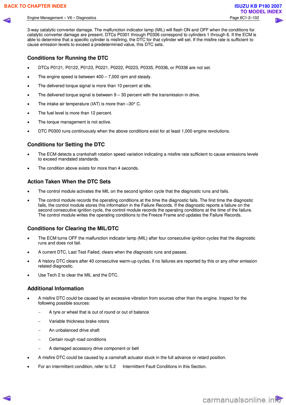
3-way catalytic converter damage. The malfunction indicator lamp (MIL) will flash ON and OFF when the conditions for
catalytic converter damage are present. DTCs P0301 through P0306 correspond to cylinders 1 through 6. If the ECM is
able to determine that a specific cylinder is misfiring, the DTC for that cylinder will set. If the misfire rate is sufficient to
cause emission levels to exceed a predetermined value, this DTC sets.
Conditions for Running the DTC
• DTCs P0121, P0122, P0123, P0221, P0222, P0223, P0335, P0336, or P0338 are not set.
• The engine speed is between 400 – 7,000 rpm and steady.
• The delivered torque signal is more than 10 percent at idle.
• The delivered torque signal is between 9 – 30 percent with the transmission in drive.
• The intake air temperature (IAT) is more than –30° C.
• The fuel level is more than 12 percent.
• The torque management is not active.
• DTC P0300 runs continuously when the above conditions exist for at least 1,000 engine revolutions.
Conditions for Setting the DTC
• The ECM detects a crankshaft rotation speed variation indicating a misfire rate sufficient to cause emissions levels
to exceed mandated standards.
• The condition above exists for more than 4 seconds.
Action Taken When the DTC Sets
• The control module activates the MIL on the second ignition cycle that the diagnostic runs and fails.
• The control module records the operating conditions at the time the diagnostic fails. The first time the diagnostic
fails, the control module stores this information in the Failure Records. If the diagnostic reports a failure on the
second consecutive ignition cycle, the control module records the operating conditions at the time of the failure.
The control module writes the operating conditions to the Freeze Frame and updates the Failure Records.
Conditions for Clearing the MIL/DTC
• The ECM turns OFF the malfunction indicator lamp (MIL) after four consecutive ignition cycles that the diagnostic
runs and does not fail.
• A current DTC, Last Test Failed, clears when the diagnostic runs and passes.
• A history DTC clears after 40 consecutive warm-up cycles, if no failures are reported by this or any other emission
related diagnostic.
• Use Tech 2 to clear the MIL and the DTC.
Additional Information
• A misfire DTC could be caused by an excessive vibration from sources other than the engine. Inspect for the
following possible sources:
− A tyre or wheel that is out of round or out of balance
− Variable thickness brake rotors
− An unbalanced drive shaft
− Certain rough road conditions
− A damaged accessory drive component or belt
• A misfire DTC could be caused by a camshaft actuator stuck in the full advance or retard position.
• For an intermittent condition, refer to 5.2 Intermittent Fault Conditions in this Section.
BACK TO CHAPTER INDEX
TO MODEL INDEX
ISUZU KB P190 2007
Page 3381 of 6020
Engine Management – V6 – Diagnostics Page 6C1-2–103
Test Description
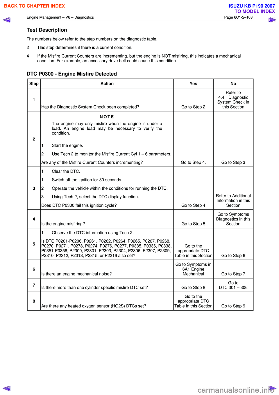
The numbers below refer to the step numbers on the diagnostic table.
2 This step determines if there is a current condition.
4 If the Misfire Current Counters are incrementing, but the engine is NOT misfiring, this indicates a mechanical condition. For example, an accessory drive belt could cause this condition.
DTC P0300 - Engine Misfire Detected
Step Action Yes No
1
Has the Diagnostic System Check been completed? Go to Step 2 Refer to
4.4 Diagnostic
System Check in this Section
2 NOTE
The engine may only misfire when the engine is under a
load. An engine load may be necessary to verify the
condition.
1 Start the engine.
2 Use Tech 2 to monitor the Misfire Current Cyl 1 – 6 parameters.
Are any of the Misfire Current Counters incrementing? Go to Step 4. Go to Step 3
3 1 Clear the DTC.
1 Switch off the ignition for 30 seconds.
2 Operate the vehicle within the conditions for running the DTC.
3 Using Tech 2, select the DTC display function.
Does DTC P0300 fail this ignition cycle? Go to Step 4 Refer to Additional
Information in this Section
4 Is the engine misfiring? Go to Step 5 Go to Symptoms
Diagnostics in this Section
5 1 Observe the DTC information using Tech 2.
Is DTC P0201-P0206, P0261, P0262, P0264, P0265, P0267, P0268,
P0270, P0271, P0273, P0274, P0276, P0277, P0335, P0336, P0338,
P0351-P0356, P2300, P2301, P2303, P2304, P2306, P2307, P2309,
P2310, P2312, P2313, P2315, or P2316 also set? Go to the
appropriate DTC
Table in this Section Go to Step 6
6 Is there an engine mechanical noise? Go to Symptoms in
6A1 Engine Mechanical Go to Step 7
7 Is there more than one cylinder specific misfire DTC set? Go to Step 8 Go to
DTC 301 – 306
8 Are there any heated oxygen sensor (HO2S) DTCs set? Go to the
appropriate DTC
Table in this Section Go to Step 9
BACK TO CHAPTER INDEX
TO MODEL INDEX
ISUZU KB P190 2007
Page 3382 of 6020

Engine Management – V6 – Diagnostics Page 6C1-2–104
Step Action Yes No
9 1 Inspect or test for the following conditions:
• Inspect the vacuum hoses for splits, kinks, and proper
connections.
• Inspect the throttle body and the intake manifold for
vacuum leaks.
• Inspect the crankcase ventilation valve and / or system for
any vacuum leaks.
• Test for the correct fuel pressure. Refer to 6C Fuel System
– V6.
• Inspect the fuel system for any restrictions, leaks or fuel
contamination. Refer to 6C Fuel System – V6.
• Inspect for fouled or damaged spark plugs. Determine
what caused the spark plugs to foul. Refer to 6C1-3
Engine Management – Service Operations.
• Inspect the exhaust system for restrictions. Refer to 6F
Exhaust System – V6.
• Inspect the engine control grounds for being clean, tight,
and in the correct location.
• Inspect for a camshaft actuator stuck in the full advance or
retard position.
2 Repair as required.
Did you find and correct the condition? Go to Step 10 Go to Symptoms in
6A1 Engine
Mechanical – V6
10 1 Use Tech 2 to clear the DTCs.
2 Switch off the ignition for 30 seconds.
3 Start the engine.
4 Operate the vehicle within the Conditions for Running DTC 300.
Did the DTC fail this ignition? Go to Step 2 Go to Step 11
11 1 Using Tech 2, select the DTC display function.
Does Tech display any DTCs? Go to the
appropriate DTC
Table in this Section System OK
When all diagnosis and repairs are completed, clear all DTCs and verify correct operation
7.17 DTC P0301, P0302, P0303, P0304, P0305
or P0306
DTC Descriptor
This diagnostic procedure supports the following DTCs:
• DTC P0301 – Cylinder 1 Misfire Detected
• DTC P0302 – Cylinder 2 Misfire Detected
• DTC P0303 – Cylinder 3 Misfire Detected
• DTC P0304 – Cylinder 4 Misfire Detected
• DTC P0305 – Cylinder 5 Misfire Detected
• DTC P0306 – Cylinder 6 Misfire Detected
BACK TO CHAPTER INDEX
TO MODEL INDEX
ISUZU KB P190 2007
Page 3383 of 6020
Engine Management – V6 – Diagnostics Page 6C1-2–105
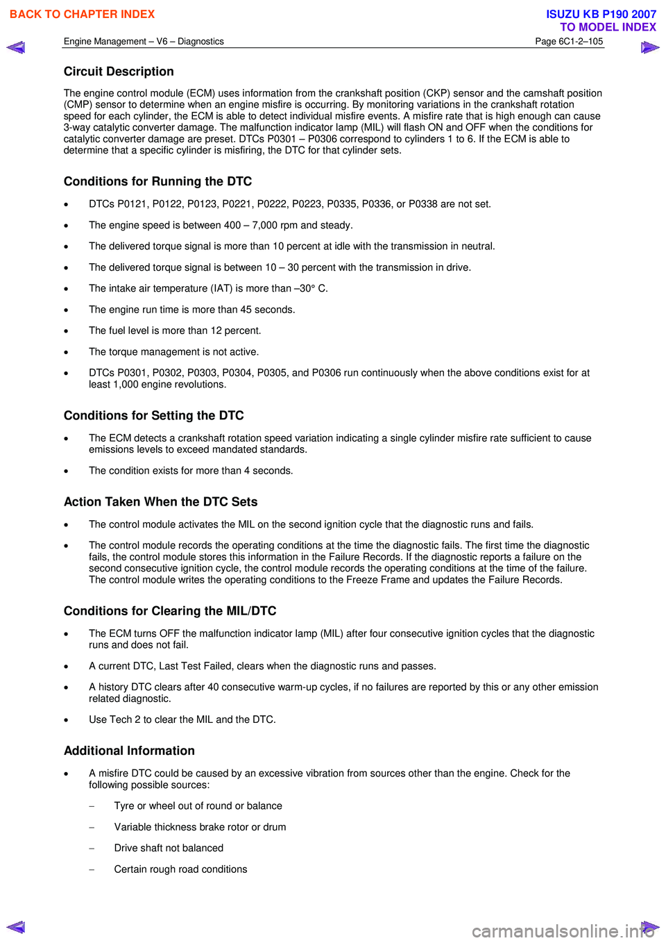
Circuit Description
The engine control module (ECM) uses information from the crankshaft position (CKP) sensor and the camshaft position
(CMP) sensor to determine when an engine misfire is occurring. By monitoring variations in the crankshaft rotation
speed for each cylinder, the ECM is able to detect individual misfire events. A misfire rate that is high enough can cause
3-way catalytic converter damage. The malfunction indicator lamp (MIL) will flash ON and OFF when the conditions for
catalytic converter damage are preset. DTCs P0301 – P0306 correspond to cylinders 1 to 6. If the ECM is able to
determine that a specific cylinder is misfiring, the DTC for that cylinder sets.
Conditions for Running the DTC
• DTCs P0121, P0122, P0123, P0221, P0222, P0223, P0335, P0336, or P0338 are not set.
• The engine speed is between 400 – 7,000 rpm and steady.
• The delivered torque signal is more than 10 percent at idle with the transmission in neutral.
• The delivered torque signal is between 10 – 30 percent with the transmission in drive.
• The intake air temperature (IAT) is more than –30° C.
• The engine run time is more than 45 seconds.
• The fuel level is more than 12 percent.
• The torque management is not active.
• DTCs P0301, P0302, P0303, P0304, P0305, and P0306 run continuously when the above conditions exist for at
least 1,000 engine revolutions.
Conditions for Setting the DTC
• The ECM detects a crankshaft rotation speed variation indicating a single cylinder misfire rate sufficient to cause
emissions levels to exceed mandated standards.
• The condition exists for more than 4 seconds.
Action Taken When the DTC Sets
• The control module activates the MIL on the second ignition cycle that the diagnostic runs and fails.
• The control module records the operating conditions at the time the diagnostic fails. The first time the diagnostic
fails, the control module stores this information in the Failure Records. If the diagnostic reports a failure on the
second consecutive ignition cycle, the control module records the operating conditions at the time of the failure.
The control module writes the operating conditions to the Freeze Frame and updates the Failure Records.
Conditions for Clearing the MIL/DTC
• The ECM turns OFF the malfunction indicator lamp (MIL) after four consecutive ignition cycles that the diagnostic
runs and does not fail.
• A current DTC, Last Test Failed, clears when the diagnostic runs and passes.
• A history DTC clears after 40 consecutive warm-up cycles, if no failures are reported by this or any other emission
related diagnostic.
• Use Tech 2 to clear the MIL and the DTC.
Additional Information
• A misfire DTC could be caused by an excessive vibration from sources other than the engine. Check for the
following possible sources:
− Tyre or wheel out of round or balance
− Variable thickness brake rotor or drum
− Drive shaft not balanced
− Certain rough road conditions
BACK TO CHAPTER INDEX
TO MODEL INDEX
ISUZU KB P190 2007
Page 3384 of 6020
Engine Management – V6 – Diagnostics Page 6C1-2–106
− Damaged accessory drive belt
• For an intermittent condition, refer to 5.2 Intermittent Fault Conditions in this Section.
• Since a fault condition in a wiring connector may trigger DTCs, always test the connectors related to this
diagnostic procedure for shorted terminals or poor wiring connection before replacing any component. Refer to 8A
Electrical - Body and Chassis for information on electrical fault diagnosis.
• To assist diagnosis, refer to 3 W iring Diagrams and Connector Charts in this Section, for the system wiring
diagram and connector charts.
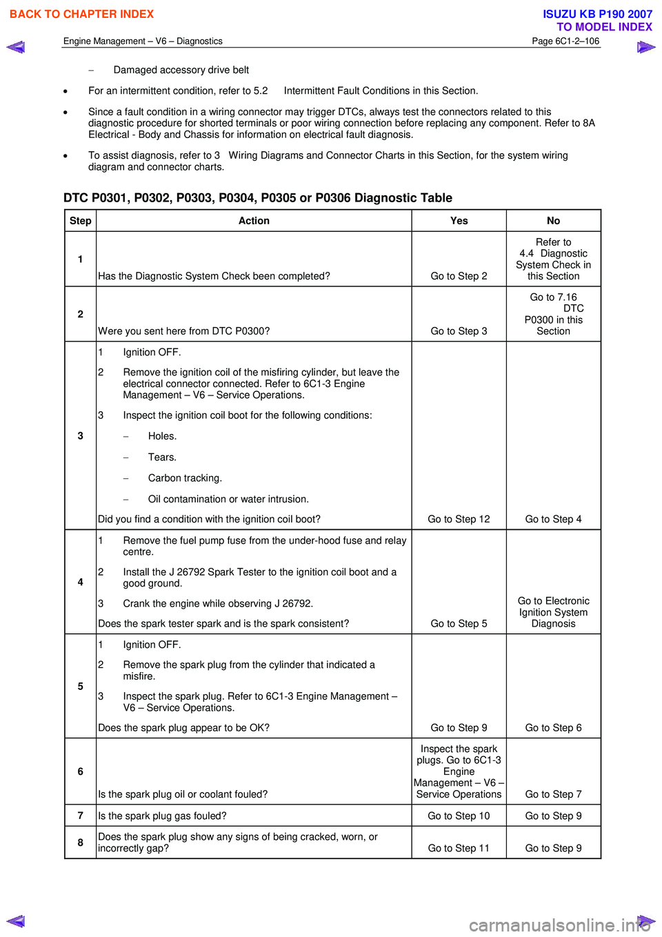
DTC P0301, P0302, P0303, P0304, P0305 or P0306 Diagnostic Table
Step Action Yes No
1
Has the Diagnostic System Check been completed? Go to Step 2 Refer to
4.4 Diagnostic
System Check in this Section
2
W ere you sent here from DTC P0300? Go to Step 3 Go to 7.16
DTC P0300 in this Section
3 1 Ignition OFF.
2 Remove the ignition coil of the misfiring cylinder, but leave the electrical connector connected. Refer to 6C1-3 Engine
Management – V6 – Service Operations.
3 Inspect the ignition coil boot for the following conditions:
− Holes.
− Tears.
− Carbon tracking.
− Oil contamination or water intrusion.
Did you find a condition with the ignition coil boot? Go to Step 12 Go to Step 4
4 1 Remove the fuel pump fuse from the under-hood fuse and relay
centre.
2 Install the J 26792 Spark Tester to the ignition coil boot and a good ground.
3 Crank the engine while observing J 26792.
Does the spark tester spark and is the spark consistent? Go to Step 5 Go to Electronic
Ignition System Diagnosis
5 1 Ignition OFF.
2 Remove the spark plug from the cylinder that indicated a misfire.
3 Inspect the spark plug. Refer to 6C1-3 Engine Management – V6 – Service Operations.
Does the spark plug appear to be OK? Go to Step 9 Go to Step 6
6
Is the spark plug oil or coolant fouled? Inspect the spark
plugs. Go to 6C1-3 Engine
Management – V6 – Service Operations Go to Step 7
7 Is the spark plug gas fouled? Go to Step 10 Go to Step 9
8 Does the spark plug show any signs of being cracked, worn, or
incorrectly gap? Go to Step 11 Go to Step 9
BACK TO CHAPTER INDEX
TO MODEL INDEX
ISUZU KB P190 2007
Page 3385 of 6020
Engine Management – V6 – Diagnostics Page 6C1-2–107
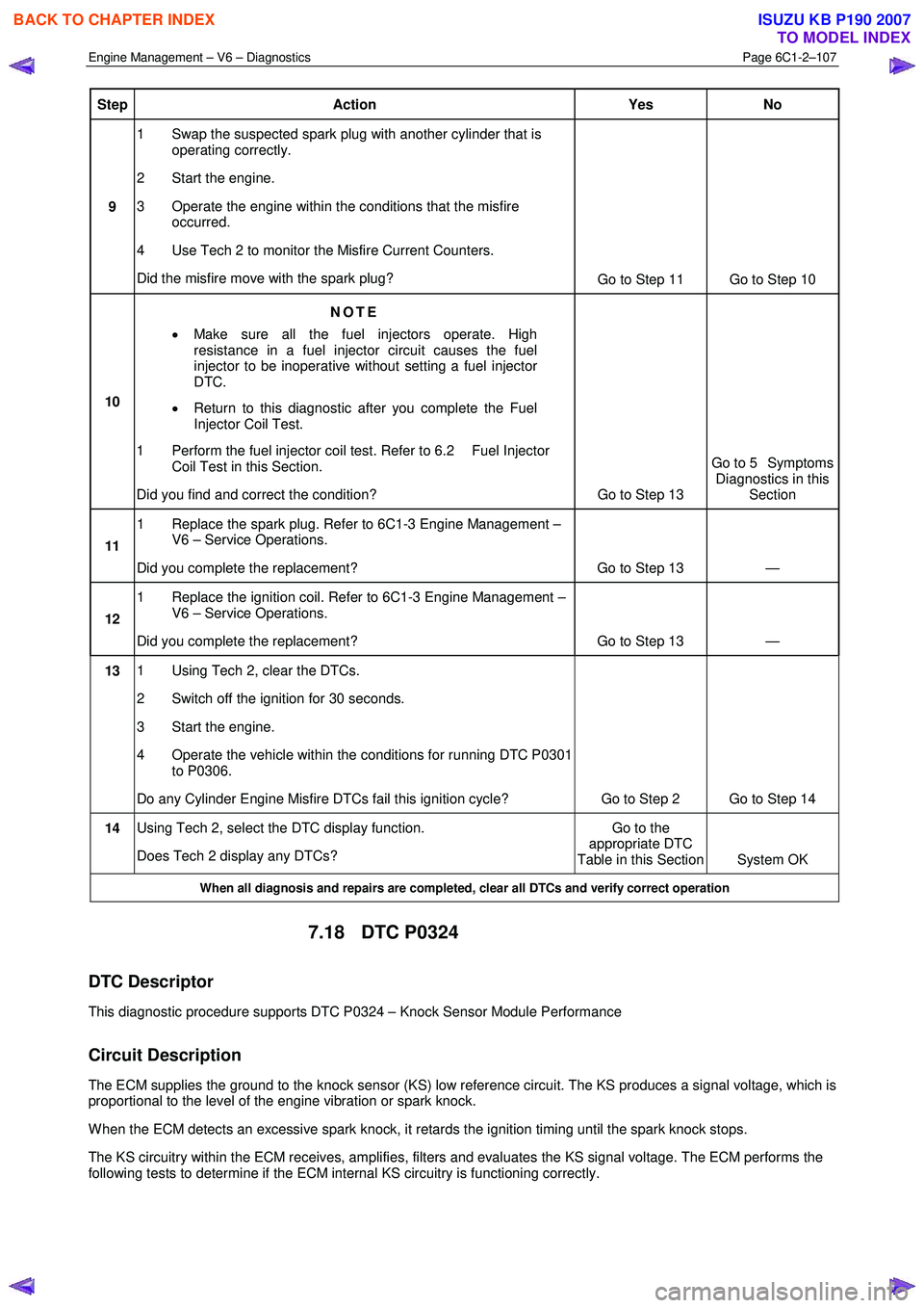
Step Action Yes No
9 1 Swap the suspected spark plug with another cylinder that is
operating correctly.
2 Start the engine.
3 Operate the engine within the conditions that the misfire occurred.
4 Use Tech 2 to monitor the Misfire Current Counters.
Did the misfire move with the spark plug? Go to Step 11 Go to Step 10
10 NOTE
• Make sure all the fuel injectors operate. High
resistance in a fuel injector circuit causes the fuel
injector to be inoperative without setting a fuel injector
DTC.
• Return to this diagnostic after you complete the Fuel
Injector Coil Test.
1 Perform the fuel injector coil test. Refer to 6.2 Fuel Injector Coil Test in this Section.
Did you find and correct the condition? Go to Step 13 Go to 5 Symptoms
Diagnostics in this Section
11 1 Replace the spark plug. Refer to 6C1-3 Engine Management –
V6 – Service Operations.
Did you complete the replacement? Go to Step 13 —
12 1 Replace the ignition coil. Refer to 6C1-3 Engine Management –
V6 – Service Operations.
Did you complete the replacement? Go to Step 13 —
13 1 Using Tech 2, clear the DTCs.
2 Switch off the ignition for 30 seconds.
3 Start the engine.
4 Operate the vehicle within the conditions for running DTC P0301 to P0306.
Do any Cylinder Engine Misfire DTCs fail this ignition cycle? Go to Step 2 Go to Step 14
14 Using Tech 2, select the DTC display function.
Does Tech 2 display any DTCs? Go to the
appropriate DTC
Table in this Section System OK
When all diagnosis and repairs are completed, clear all DTCs and verify correct operation
7.18 DTC P0324
DTC Descriptor
This diagnostic procedure supports DTC P0324 – Knock Sensor Module Performance
Circuit Description
The ECM supplies the ground to the knock sensor (KS) low reference circuit. The KS produces a signal voltage, which is
proportional to the level of the engine vibration or spark knock.
W hen the ECM detects an excessive spark knock, it retards the ignition timing until the spark knock stops.
The KS circuitry within the ECM receives, amplifies, filters and evaluates the KS signal voltage. The ECM performs the
following tests to determine if the ECM internal KS circuitry is functioning correctly.
BACK TO CHAPTER INDEX
TO MODEL INDEX
ISUZU KB P190 2007
Page 3386 of 6020
Engine Management – V6 – Diagnostics Page 6C1-2–108
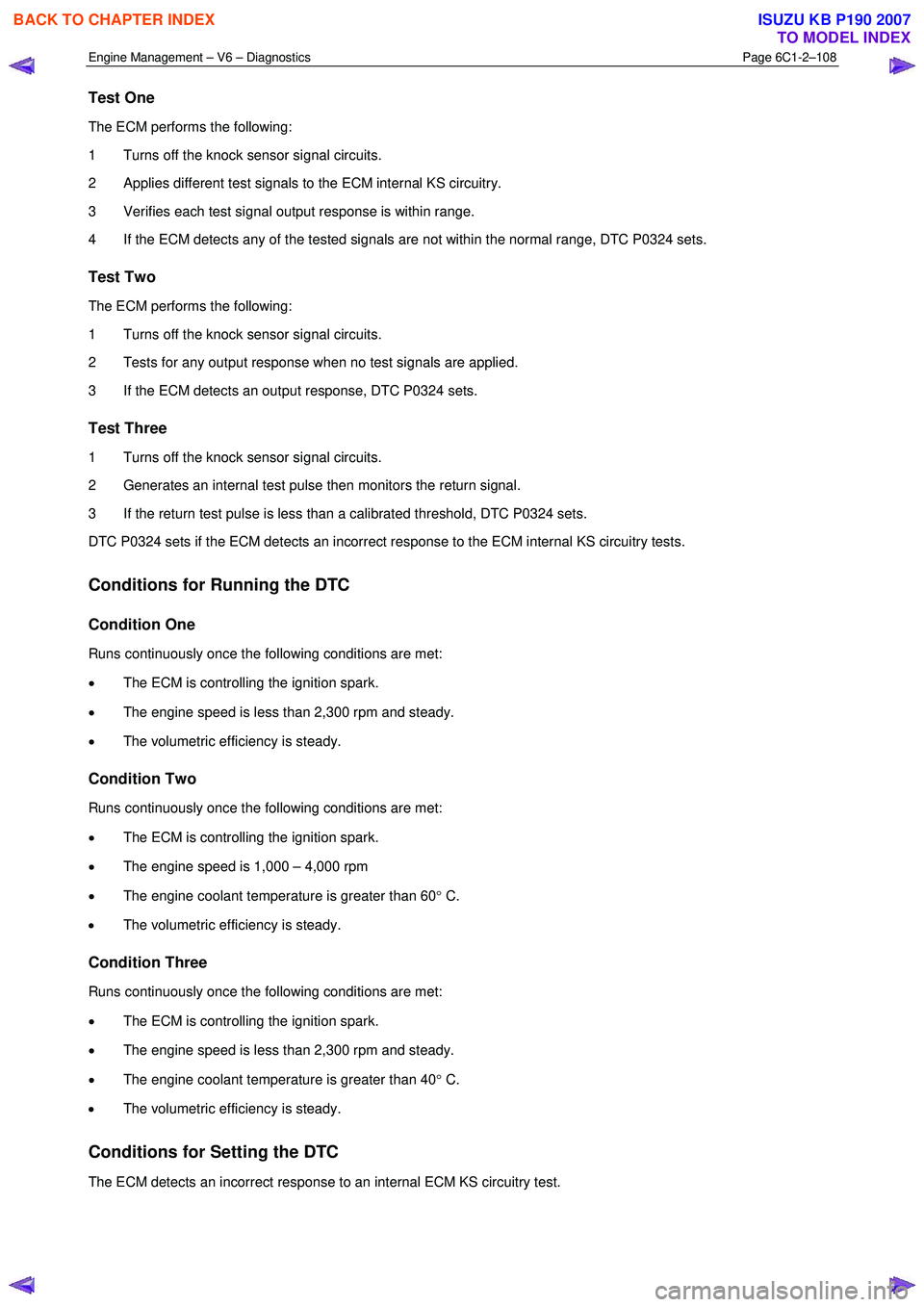
Test One
The ECM performs the following:
1 Turns off the knock sensor signal circuits.
2 Applies different test signals to the ECM internal KS circuitry.
3 Verifies each test signal output response is within range.
4 If the ECM detects any of the tested signals are not within the normal range, DTC P0324 sets.
Test Two
The ECM performs the following:
1 Turns off the knock sensor signal circuits.
2 Tests for any output response when no test signals are applied.
3 If the ECM detects an output response, DTC P0324 sets.
Test Three
1 Turns off the knock sensor signal circuits.
2 Generates an internal test pulse then monitors the return signal.
3 If the return test pulse is less than a calibrated threshold, DTC P0324 sets.
DTC P0324 sets if the ECM detects an incorrect response to the ECM internal KS circuitry tests.
Conditions for Running the DTC
Condition One
Runs continuously once the following conditions are met:
• The ECM is controlling the ignition spark.
• The engine speed is less than 2,300 rpm and steady.
• The volumetric efficiency is steady.
Condition Two
Runs continuously once the following conditions are met:
• The ECM is controlling the ignition spark.
• The engine speed is 1,000 – 4,000 rpm
• The engine coolant temperature is greater than 60 ° C.
• The volumetric efficiency is steady.
Condition Three
Runs continuously once the following conditions are met:
• The ECM is controlling the ignition spark.
• The engine speed is less than 2,300 rpm and steady.
• The engine coolant temperature is greater than 40 ° C.
• The volumetric efficiency is steady.
Conditions for Setting the DTC
The ECM detects an incorrect response to an internal ECM KS circuitry test.
BACK TO CHAPTER INDEX
TO MODEL INDEX
ISUZU KB P190 2007
Page 3387 of 6020
Engine Management – V6 – Diagnostics Page 6C1-2–109
Conditions for Clearing the DTC
DTC P0324 – Knock Sensor (KS) Module Performance is a Type B DTC. Refer to 1.4 Diagnostic Trouble Codes in
this Section, for action taken when a Type B DTC sets and conditions for clearing Type B DTC.
Additional Information
• Refer to 6C1-1 Engine Management – V6 – General Information for details of the knock sensor (KS) system
operation.
• The ECM turns off the KS signal circuits when performing the ECM internal KS circuitry tests. DTC P0324 sets if
there is a fault condition in the internal ECM KS circuitry. Therefore, the KS and the KS signal circuits are not
tested in DTC P0324 Diagnostic Table.
• For an intermittent fault condition, refer to 5.2 Intermittent Fault Conditions in this Section.
• Since fault condition in a wiring connector may trigger DTCs, always test the connectors related to this diagnostic
procedure for shorted terminals or poor wiring connection before replacing any component. Refer to 8A Electrical -
Body and Chassis for information on electrical fault diagnosis.
• To assist diagnosis, refer to 3 W iring Diagrams and Connector Charts in this Section, for the system wiring
diagram and connector charts.
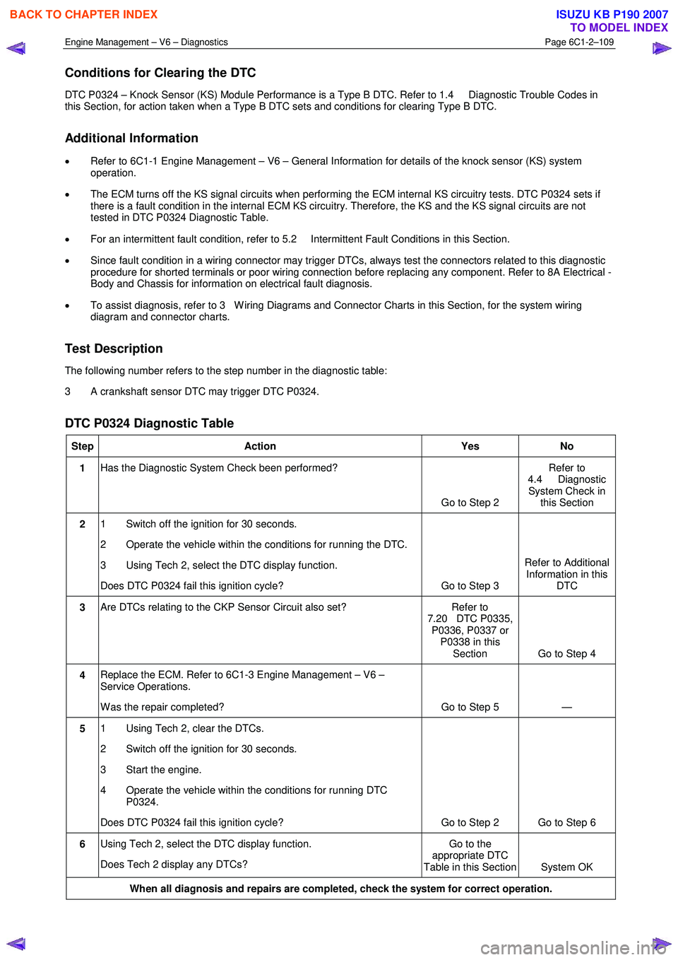
Test Description
The following number refers to the step number in the diagnostic table:
3 A crankshaft sensor DTC may trigger DTC P0324.
DTC P0324 Diagnostic Table
Step Action Yes No
1 Has the Diagnostic System Check been performed?
Go to Step 2 Refer to
4.4 Diagnostic System Check in this Section
2 1 Switch off the ignition for 30 seconds.
2 Operate the vehicle within the conditions for running the DTC.
3 Using Tech 2, select the DTC display function.
Does DTC P0324 fail this ignition cycle? Go to Step 3 Refer to Additional
Information in this DTC
3 Are DTCs relating to the CKP Sensor Circuit also set? Refer to
7.20 DTC P0335, P0336, P0337 or P0338 in this Section Go to Step 4
4 Replace the ECM. Refer to 6C1-3 Engine Management – V6 –
Service Operations.
W as the repair completed? Go to Step 5 —
5 1 Using Tech 2, clear the DTCs.
2 Switch off the ignition for 30 seconds.
3 Start the engine.
4 Operate the vehicle within the conditions for running DTC P0324.
Does DTC P0324 fail this ignition cycle? Go to Step 2 Go to Step 6
6 Using Tech 2, select the DTC display function.
Does Tech 2 display any DTCs? Go to the
appropriate DTC
Table in this Section System OK
When all diagnosis and repairs are completed, check the system for correct operation.
BACK TO CHAPTER INDEX
TO MODEL INDEX
ISUZU KB P190 2007