2007 ISUZU KB P190 sensor
[x] Cancel search: sensorPage 1332 of 6020
6E-298 Engine Control System (4JH1)
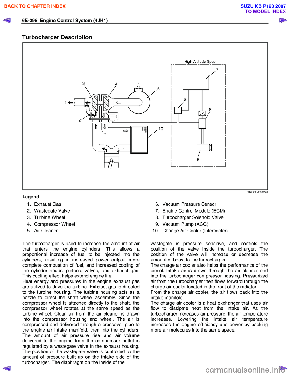
Turbocharger Description
RTW 66EMF000501
Legend
1. Exhaust Gas
2. W astegate Valve
3. Turbine W heel
4. Compressor W heel
5. Air Cleaner
6. Vacuum Pressure Sensor
7. Engine Control Module (ECM)
8. Turbocharger Solenoid Valve
9. Vacuum Pump (ACG)
10. Change Air Cooler (Intercooler)
The turbocharger is used to increase the amount of ai
r
that enters the engine cylinders. This allows a
proportional increase of fuel to be injected into the
cylinders, resulting in increased power output, more
complete combustion of fuel, and increased cooling o
f
the cylinder heads, pistons, valves, and exhaust gas.
This cooling effect helps extend engine life.
Heat energy and pressures in the engine exhaust gas
are utilized to drive the turbine. Exhaust gas is directed
to the turbine housing. The turbine housing acts as a
nozzle to direct the shaft wheel assembly. Since the
compressor wheel is attached directly to the shaft, the
compressor wheel rotates at the same speed as the
turbine wheel. Clean air from the air cleaner is drawn
into the compressor housing and wheel. The air is
compressed and delivered through a crossover pipe to
the engine air intake manifold, then into the cylinders.
The amount of air pressure rise and air volume
delivered to the engine from the compressor outlet is
regulated by a wastegate valve in the exhaust housing.
The position of the wastegate valve is controlled by the
amount of pressure built up on the intake side of the
turbocharger. The diaphragm on the inside of the
wastegate is pressure sensitive, and controls the
position of the valve inside the turbocharger. The
position of the valve will increase or decrease the
amount of boost to the turbocharger.
The charge air cooler also helps the performance of the
diesel. Intake air is drawn through the air cleaner and
into the turbocharger compressor housing. Pressurized
air from the turbocharger then flows forward through the
charge air cooler located in the front of the radiator.
From the charge air cooler, the air flows back into the
intake manifold.
The charge air cooler is a heat exchanger that uses ai
r
flow to dissipate heat from the intake air. As the
turbocharger increases air pressure, the air temperature
increases. Lowering the intake air temperature
increases the engine efficiency and power by packing
more air molecules into the same space.
BACK TO CHAPTER INDEX
TO MODEL INDEX
ISUZU KB P190 2007
Page 1340 of 6020
EXHAUST SYSTEM 6F – 7
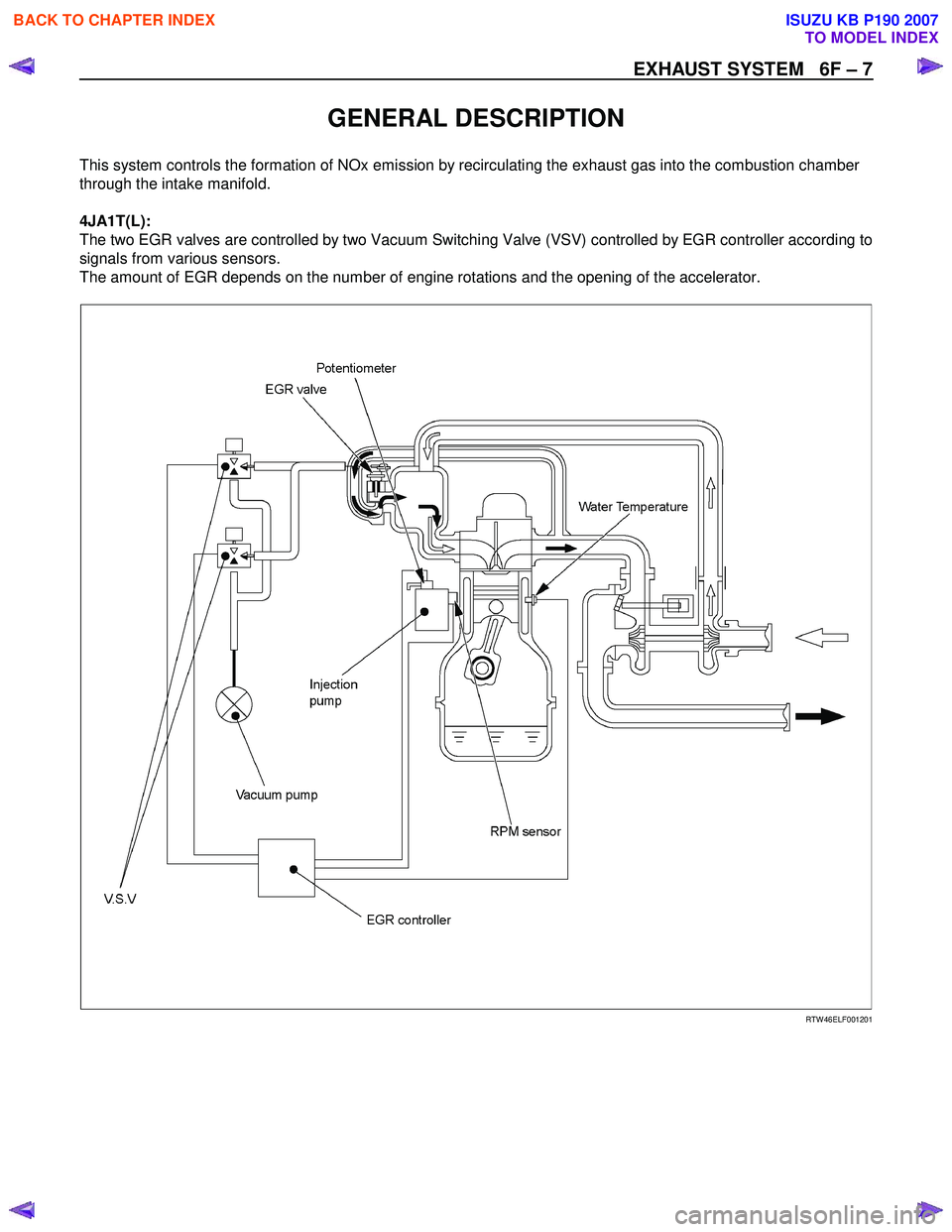
GENERAL DESCRIPTION
This system controls the formation of NOx emission by recirculating the exhaust gas into the combustion chamber
through the intake manifold.
4JA1T(L):
The two EGR valves are controlled by two Vacuum Switching Valve (VSV) controlled by EGR controller according to
signals from various sensors.
The amount of EGR depends on the number of engine rotations and the opening of the accelerator.
RTW 46ELF001201
BACK TO CHAPTER INDEX
TO MODEL INDEX
ISUZU KB P190 2007
Page 1365 of 6020
ENGINE MECHANICAL (4JK1/4JJ1) 6A-5
EGR system
Based upon data, including water temperature, engine
speeds or engine loads, it is controlled via Engine
Control Module (ECM) to purify exhaust by recycling
part of it.
Its main components include an EGR valve, an EGR
cooler and various sensors.
Connecting rod cap bolt
The angular tightening method of the connecting rod
cap bolt further increases reliability and durability.
Fuel rail-type electronic control injection system
The fuel rail-type electronic control injection system is
composed of a fuel supply pump that sets the target
pressure of high-pressure fuel and supply it, a fuel rail
that measures such high-pressure fuel and a fuel
injector that turns it into a fine spray and injects it. Each
is controlled via ECM based upon various signals, while
injection timing or fuel injection quantity is controlled
under every possible driving condition.
Fuel injector
The fuel injector is a 6-hole nozzle that adjusts fuel
injection quantity or injection timing by opening o
r
closing an electromagnetic valve on the head of the fuel
injector.
ECM corrects the dispersion of fuel injection quantit
y
between fuel injector according to ID code data in
memory. At the replacement of fuel injector, ID code
data should be stored in ECM.
Fuel filter with sedimenter
It is a fuel filter with sedimenter that gets rid of water by
making use of the difference in specific gravity between
light oil and water, which comes with an indicator that
notifies you that it is filled with water.
Preheating system
The preheating system consists of the ECM, the glow
relay, glow plugs and the glow indicator lamp. The
preheating system is operated when the engine coolant
temperature is low, and makes the engine easy to start.
Lubrication system
It is an oil filter with full-flow bypass, which uses a
water-cool oil cooler and oil jet to cool the piston.
Functional inspection
Inspection/adjustment of valve clearance 1. Inspection of valve clearance
• Remove the fuel injector harness assembly.
• Remove the leak off hose.
• Remove the cylinder head cover.
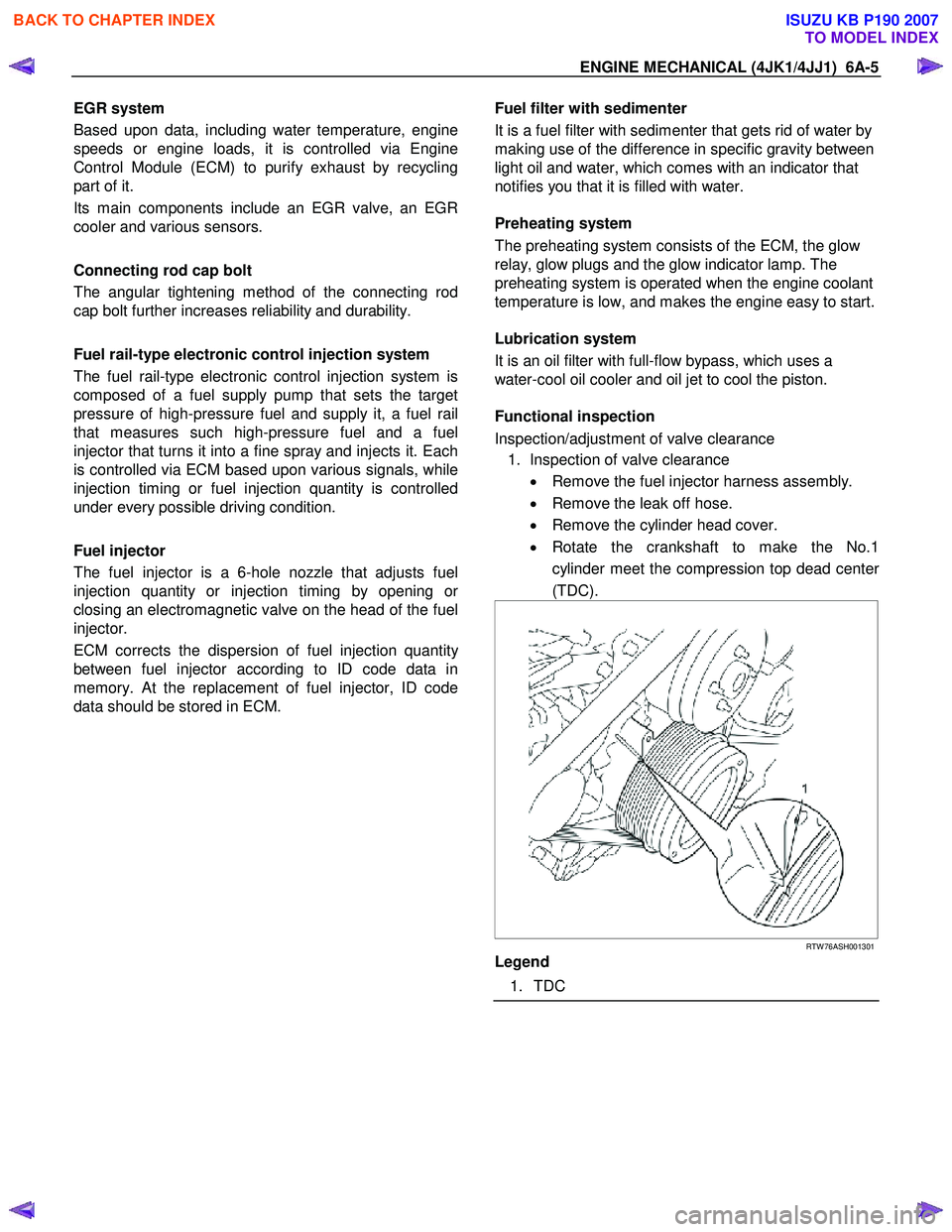
• Rotate the crankshaft to make the No.1
cylinder meet the compression top dead cente
r
(TDC).
RTW 76ASH001301
Legend
1. TDC
BACK TO CHAPTER INDEX
TO MODEL INDEX
ISUZU KB P190 2007
Page 1368 of 6020
6A-8 ENGINE MECHANICAL (4JK1/4JJ1)
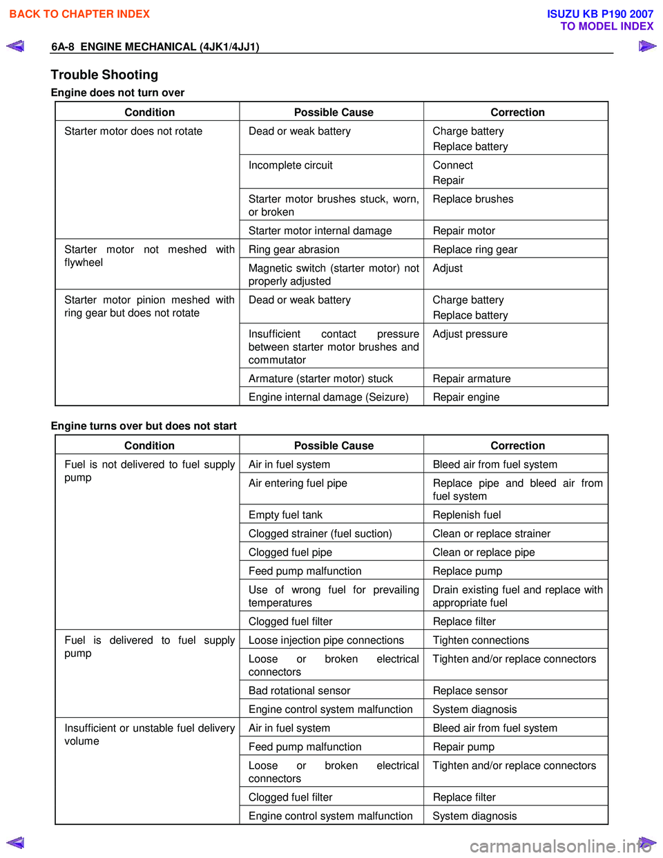
Trouble Shooting
Engine does not turn over
Condition Possible Cause Correction
Dead or weak battery Charge battery
Replace battery
Incomplete circuit Connect
Repair
Starter motor brushes stuck, worn,
or broken Replace brushes
Starter motor does not rotate
Starter motor internal damage Repair motor
Ring gear abrasion Replace ring gear Starter motor not meshed with
flywheel Magnetic switch (starter motor) not
properly adjusted Adjust
Dead or weak battery
Charge battery
Replace battery
Insufficient contact pressure
between starter motor brushes and
commutator Adjust pressure
Armature (starter motor) stuck Repair armature
Starter motor pinion meshed with
ring gear but does not rotate
Engine internal damage (Seizure) Repair engine
Engine turns over but does not start
Condition Possible Cause Correction
Air in fuel system Bleed air from fuel system
Air entering fuel pipe Replace pipe and bleed air from
fuel system
Empty fuel tank Replenish fuel
Clogged strainer (fuel suction) Clean or replace strainer
Clogged fuel pipe Clean or replace pipe
Feed pump malfunction Replace pump
Use of wrong fuel for prevailing
temperatures Drain existing fuel and replace with
appropriate fuel
Fuel is not delivered to fuel supply
pump
Clogged fuel filter Replace filter
Loose injection pipe connections Tighten connections
Loose or broken electrical
connectors Tighten and/or replace connectors
Bad rotational sensor
Replace sensor
Fuel is delivered to fuel supply
pump
Engine control system malfunction System diagnosis
Air in fuel system Bleed air from fuel system
Feed pump malfunction Repair pump
Loose or broken electrical
connectors Tighten and/or replace connectors
Clogged fuel filter
Replace filter
Insufficient or unstable fuel delivery
volume
Engine control system malfunction System diagnosis
BACK TO CHAPTER INDEX
TO MODEL INDEX
ISUZU KB P190 2007
Page 1369 of 6020

ENGINE MECHANICAL (4JK1/4JJ1) 6A-9
Excessive black exhaust smoke
Condition Possible Cause Correction
Bad injection timing Engine control system malfunction System diagnosis
Carbon deposit at nozzle tip Clean fuel injector assembly
Sticking nozzle Replace fuel injector assembly
Bad fuel injector condition
Engine control system malfunction System diagnosis
Excessive valve clearance Adjust clearance
Sticking valve stem (valve open) Repair or replace valve
Damaged valve spring Replace spring
Valve seat abrasion Repair valve seat
Compression leakage due to
damaged piston ring Replace piston ring
Damaged gasket
Replace gasket
Insufficient compression pressure
Piston scoring Replace piston
W ater in fuel Drain existing fuel and replace with
new fuel Fuel condition
Poor fuel quality Drain existing fuel and replace with
new fuel
Clogged intake pipes Clean or replace pipes Poor engine aspiration
Clogged air cleaner element Clean or replace element
Defective sensor Replace sensor Malfunction detected by engine
control system Engine control system malfunction System diagnosis
Intake throttle valve sticking Repair or replace valve
EGR valve sticking Repair or replace valve
EGR valve and/or intake throttle
valve malfunction
Engine control system malfunction System diagnosis
Damaged turbocharger blade Replace turbocharger
Rough turbocharger shaft rotation Replace turbocharger
Oil leakage from oil seal Replace turbocharger
Turbocharger malfunction
Broken actuator Replace turbocharger
BACK TO CHAPTER INDEX
TO MODEL INDEX
ISUZU KB P190 2007
Page 1370 of 6020
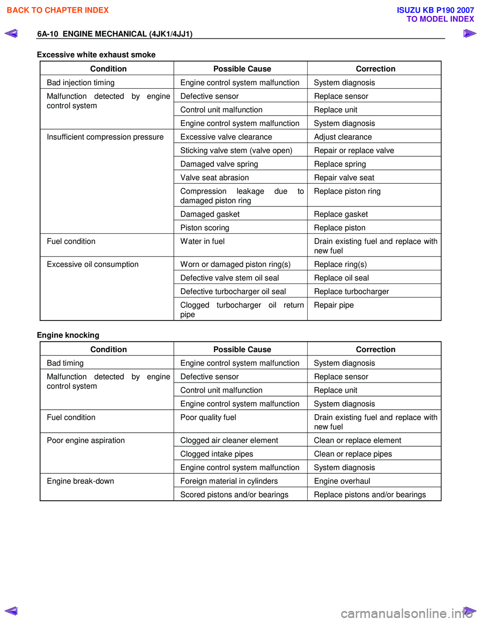
6A-10 ENGINE MECHANICAL (4JK1/4JJ1)
Excessive white exhaust smoke
Condition Possible Cause Correction
Bad injection timing Engine control system malfunction System diagnosis
Defective sensor Replace sensor
Control unit malfunction Replace unit
Malfunction detected by engine
control system
Engine control system malfunction System diagnosis
Excessive valve clearance Adjust clearance
Sticking valve stem (valve open) Repair or replace valve
Damaged valve spring Replace spring
Valve seat abrasion Repair valve seat
Compression leakage due to
damaged piston ring Replace piston ring
Damaged gasket
Replace gasket
Insufficient compression pressure
Piston scoring Replace piston
Fuel condition W ater in fuel Drain existing fuel and replace with
new fuel
W orn or damaged piston ring(s) Replace ring(s)
Defective valve stem oil seal Replace oil seal
Defective turbocharger oil seal Replace turbocharger
Excessive oil consumption
Clogged turbocharger oil return
pipe Repair pipe
Engine knocking
Condition Possible Cause Correction
Bad timing Engine control system malfunction System diagnosis
Defective sensor Replace sensor
Control unit malfunction Replace unit
Malfunction detected by engine
control system
Engine control system malfunction System diagnosis
Fuel condition Poor quality fuel Drain existing fuel and replace with
new fuel
Clogged air cleaner element Clean or replace element
Clogged intake pipes Clean or replace pipes
Poor engine aspiration
Engine control system malfunction System diagnosis
Foreign material in cylinders Engine overhaul Engine break-down Scored pistons and/or bearings Replace pistons and/or bearings
BACK TO CHAPTER INDEX
TO MODEL INDEX
ISUZU KB P190 2007
Page 1375 of 6020
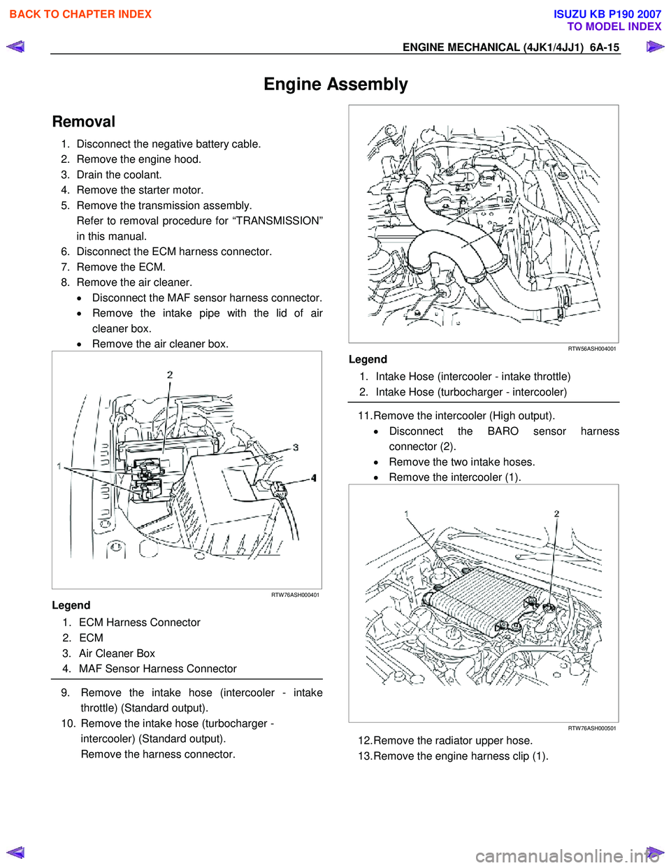
ENGINE MECHANICAL (4JK1/4JJ1) 6A-15
Engine Assembly
Removal
1. Disconnect the negative battery cable.
2. Remove the engine hood.
3. Drain the coolant.
4. Remove the starter motor.
5. Remove the transmission assembly.
Refer to removal procedure for “TRANSMISSION” in this manual.
6. Disconnect the ECM harness connector.
7. Remove the ECM.
8. Remove the air cleaner. • Disconnect the MAF sensor harness connector.
• Remove the intake pipe with the lid of ai
r
cleaner box.
• Remove the air cleaner box.
RTW 76ASH000401
Legend
1. ECM Harness Connector
2. ECM
3. Air Cleaner Box
4. MAF Sensor Harness Connector
9. Remove the intake hose (intercooler - intake
throttle) (Standard output).
10. Remove the intake hose (turbocharger - intercooler) (Standard output).
Remove the harness connector.
RTW 56ASH004001
Legend
1. Intake Hose (intercooler - intake throttle)
2. Intake Hose (turbocharger - intercooler)
11. Remove the intercooler (High output).
• Disconnect the BARO sensor harness
connector (2).
• Remove the two intake hoses.
• Remove the intercooler (1).
RTW 76ASH000501
12. Remove the radiator upper hose.
13. Remove the engine harness clip (1).
BACK TO CHAPTER INDEX
TO MODEL INDEX
ISUZU KB P190 2007
Page 1378 of 6020
6A-18 ENGINE MECHANICAL (4JK1/4JJ1)
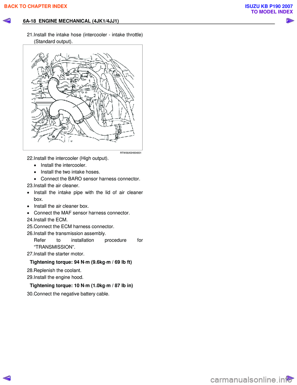
21.Install the intake hose (intercooler - intake throttle)
(Standard output).
RTW 56ASH004001
22.Install the intercooler (High output).
• Install the intercooler.
• Install the two intake hoses.
• Connect the BARO sensor harness connector.
23.Install the air cleaner.
• Install the intake pipe with the lid of air cleane
r
box.
• Install the air cleaner box.
• Connect the MAF sensor harness connector.
24.Install the ECM.
25.Connect the ECM harness connector.
26.Install the transmission assembly.
Refer to installation procedure fo
r
“TRANSMISSION”.
27.Install the starter motor.
Tightening torque: 94 N ⋅
⋅⋅
⋅
m (9.6kg ⋅
⋅⋅
⋅
m / 69 lb ft)
28.Replenish the coolant.
29.Install the engine hood.
Tightening torque: 10 N ⋅
⋅⋅
⋅
m (1.0kg ⋅
⋅⋅
⋅
m / 87 lb in)
30.Connect the negative battery cable.
BACK TO CHAPTER INDEX
TO MODEL INDEX
ISUZU KB P190 2007