2007 ISUZU KB P190 relay
[x] Cancel search: relayPage 3505 of 6020
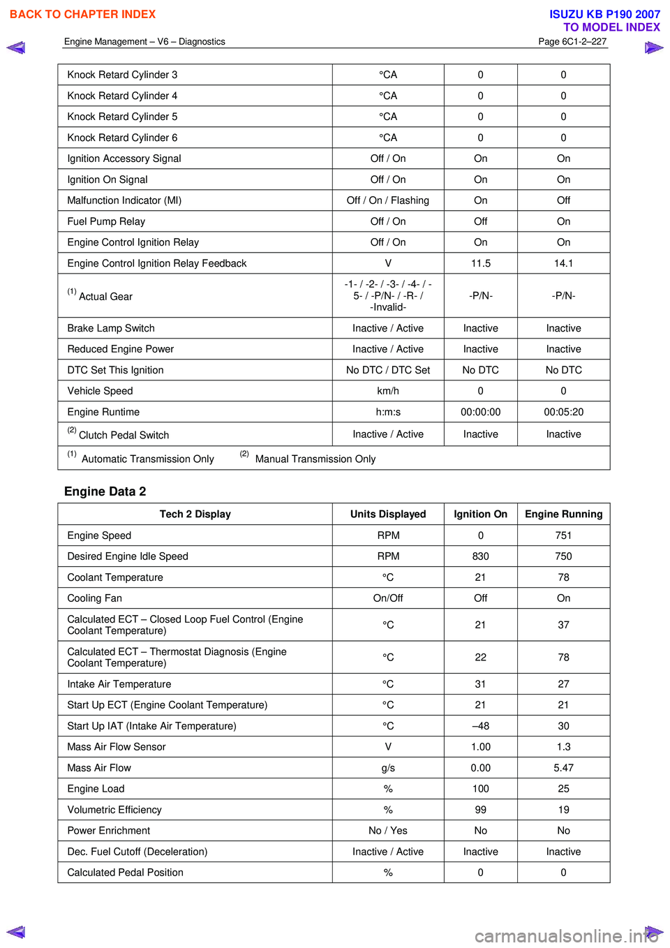
Engine Management – V6 – Diagnostics Page 6C1-2–227
Knock Retard Cylinder 3 °CA 0 0
Knock Retard Cylinder 4 °CA 0 0
Knock Retard Cylinder 5 °CA 0 0
Knock Retard Cylinder 6 °CA 0 0
Ignition Accessory Signal Off / On On On
Ignition On Signal Off / On On On
Malfunction Indicator (MI) Off / On / Flashing On Off
Fuel Pump Relay Off / On Off On
Engine Control Ignition Relay Off / On On On
Engine Control Ignition Relay Feedback V 11.5 14.1
(1) Actual Gear -1- / -2- / -3- / -4- / -
5- / -P/N- / -R- / -Invalid- -P/N- -P/N-
Brake Lamp Switch
Inactive / Active Inactive Inactive
Reduced Engine Power Inactive / Active Inactive Inactive
DTC Set This Ignition No DTC / DTC Set No DTC No DTC
Vehicle Speed km/h 0 0
Engine Runtime h:m:s 00:00:00 00:05:20
(2) Clutch Pedal Switch Inactive / Active Inactive Inactive
(1) Automatic Transmission Only (2) Manual Transmission Only
Engine Data 2
Tech 2 Display
Units Displayed Ignition On Engine Running
Engine Speed RPM 0 751
Desired Engine Idle Speed RPM 830 750
Coolant Temperature °C 21 78
Cooling Fan On/Off Off On
Calculated ECT – Closed Loop Fuel Control (Engine
Coolant Temperature) °C 21 37
Calculated ECT – Thermostat Diagnosis (Engine
Coolant Temperature) °C 22 78
Intake Air Temperature
°C 31 27
Start Up ECT (Engine Coolant Temperature) °C 21 21
Start Up IAT (Intake Air Temperature) °C –48 30
Mass Air Flow Sensor V 1.00 1.3
Mass Air Flow g/s 0.00 5.47
Engine Load % 100 25
Volumetric Efficiency % 99 19
Power Enrichment No / Yes No No
Dec. Fuel Cutoff (Deceleration) Inactive / Active Inactive Inactive
Calculated Pedal Position % 0 0
BACK TO CHAPTER INDEX
TO MODEL INDEX
ISUZU KB P190 2007
Page 3506 of 6020
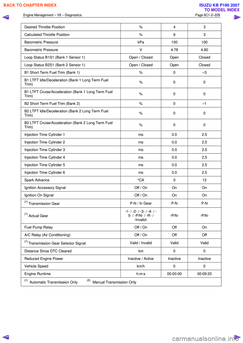
Engine Management – V6 – Diagnostics Page 6C1-2–228
Desired Throttle Position % 4 3
Calculated Throttle Position % 6 3
Barometric Pressure kPa 100 100
Barometric Pressure V 4.78 4.80
Loop Status B1S1 (Bank 1 Sensor 1) Open / Closed Open Closed
Loop Status B2S1 (Bank 2 Sensor 1) Open / Closed Open Closed
B1 Short Term Fuel Trim (Bank 1) % 0 –3
B1 LTFT Idle/Deceleration (Bank 1 Long Term Fuel
Trim) % 0 0
B1 LTFT Cruise/Acceleration (Bank 1 Long Term Fuel
Trim) % 0 0
B2 Short Term Fuel Trim (Bank 2)
% 0 –1
B2 LTFT Idle/Deceleration (Bank 2 Long Term Fuel
Trim) % 0 0
B2 LTFT Cruise/Acceleration (Bank 2 Long Term Fuel
Trim) % 0 0
Injection Time Cylinder 1
ms 0.0 2.5
Injection Time Cylinder 2 ms 0.0 2.5
Injection Time Cylinder 3 ms 0.0 2.5
Injection Time Cylinder 4 ms 0.0 2.5
Injection Time Cylinder 5 ms 0.0 2.5
Injection Time Cylinder 6 ms 0.0 2.5
Spark Advance °CA 0 12
Ignition Accessory Signal Off / On On On
Ignition On Signal Off / On On On
(1) Transmission Gear P-N / In Gear P-N P-N
(1) Actual Gear -1- / -2- / -3- / -4- / -
5- / -P/N- / -R- / -Invalid- -P/N- -P/N-
Fuel Pump Relay
Off / On Off On
A/C Relay (Air Conditioning) Off / On Off Off
(1) Transmission Gear Selector Signal Valid / Invalid Valid
Valid
Distance Since DTC Cleared km 0 0
Reduced Engine Power Inactive / Active Inactive Inactive
Vehicle Speed km/h 0 0
Engine Runtime h:m:s 00:00:00 00:09:20
(1) Automatic Transmission Only (2) Manual Transmission Only
BACK TO CHAPTER INDEX
TO MODEL INDEX
ISUZU KB P190 2007
Page 3508 of 6020
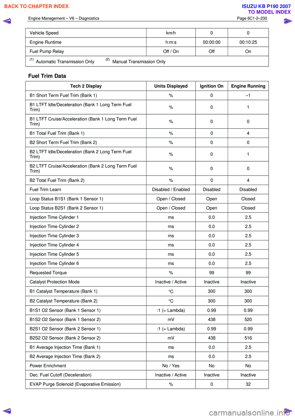
Engine Management – V6 – Diagnostics Page 6C1-2–230
Vehicle Speed km/h 0 0
Engine Runtime h:m:s 00:00:00 00:10:25
Fuel Pump Relay Off / On Off On
(1) Automatic Transmission Only (2) Manual Transmission Only
Fuel Trim Data
Tech 2 Display Units Displayed Ignition On Engine Running
B1 Short Term Fuel Trim (Bank 1) % 0 –1
B1 LTFT Idle/Deceleration (Bank 1 Long Term Fuel
Trim) % 0 1
B1 LTFT Cruise/Acceleration (Bank 1 Long Term Fuel
Trim) % 0 0
B1 Total Fuel Trim (Bank 1)
% 0 4
B2 Short Term Fuel Trim (Bank 2) % 0 0
B2 LTFT Idle/Deceleration (Bank 2 Long Term Fuel
Trim) % 0 1
B2 LTFT Cruise/Acceleration (Bank 2 Long Term Fuel
Trim) % 0 0
B2 Total Fuel Trim (Bank 2)
% 0 4
Fuel Trim Learn Disabled / Enabled Disabled Disabled
Loop Status B1S1 (Bank 1 Sensor 1) Open / Closed Open Closed
Loop Status B2S1 (Bank 2 Sensor 1) Open / Closed Open Closed
Injection Time Cylinder 1 ms 0.0 2.5
Injection Time Cylinder 2 ms 0.0 2.5
Injection Time Cylinder 3 ms 0.0 2.5
Injection Time Cylinder 4 ms 0.0 2.5
Injection Time Cylinder 5 ms 0.0 2.5
Injection Time Cylinder 6 ms 0.0 2.5
Requested Torque % 99 99
Catalyst Protection Mode Inactive / Active Inactive Inactive
B1 Catalyst Temperature (Bank 1)
°C 300 300
B2 Catalyst Temperature (Bank 2)
°C 300 300
B1S1 O2 Sensor (Bank 1 Sensor 1)
:1 (= Lambda) 0.99 0.99
B1S2 O2 Sensor (Bank 1 Sensor 2) mV 438 520
B2S1 O2 Sensor (Bank 2 Sensor 1) :1 (= Lambda) 0.99 0.99
B2S2 O2 Sensor (Bank 2 Sensor 2) mV 438 516
B1 Average Injection Time (Bank 1) ms 0.0 2.5
B2 Average Injection Time (Bank 2) ms 0.0 2.5
Power Enrichment No / Yes No No
Dec. Fuel Cutoff (Deceleration) Inactive / Active Inactive Inactive
EVAP Purge Solenoid (Evaporative Emission) % 0 32
BACK TO CHAPTER INDEX
TO MODEL INDEX
ISUZU KB P190 2007
Page 3511 of 6020
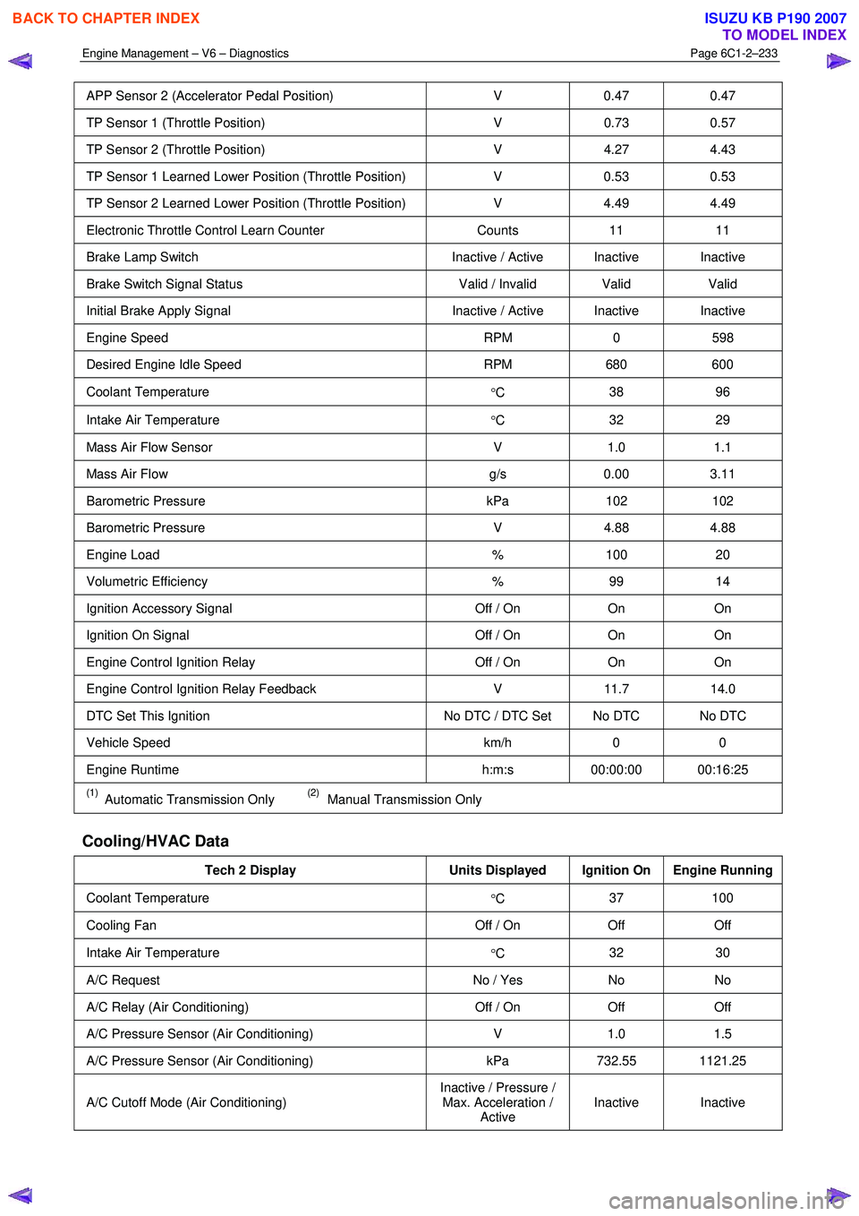
Engine Management – V6 – Diagnostics Page 6C1-2–233
APP Sensor 2 (Accelerator Pedal Position) V 0.47 0.47
TP Sensor 1 (Throttle Position) V 0.73 0.57
TP Sensor 2 (Throttle Position) V 4.27 4.43
TP Sensor 1 Learned Lower Position (Throttle Position) V 0.53 0.53
TP Sensor 2 Learned Lower Position (Throttle Position) V 4.49 4.49
Electronic Throttle Control Learn Counter Counts 11 11
Brake Lamp Switch Inactive / Active Inactive Inactive
Brake Switch Signal Status Valid / Invalid Valid Valid
Initial Brake Apply Signal Inactive / Active Inactive Inactive
Engine Speed RPM 0 598
Desired Engine Idle Speed RPM 680 600
Coolant Temperature
°C 38 96
Intake Air Temperature
°C 32 29
Mass Air Flow Sensor
V 1.0 1.1
Mass Air Flow g/s 0.00 3.11
Barometric Pressure kPa 102 102
Barometric Pressure V 4.88 4.88
Engine Load % 100 20
Volumetric Efficiency % 99 14
Ignition Accessory Signal Off / On On On
Ignition On Signal Off / On On On
Engine Control Ignition Relay Off / On On On
Engine Control Ignition Relay Feedback V 11.7 14.0
DTC Set This Ignition No DTC / DTC Set No DTC No DTC
Vehicle Speed km/h 0 0
Engine Runtime h:m:s 00:00:00 00:16:25
(1) Automatic Transmission Only (2) Manual Transmission Only
Cooling/HVAC Data
Tech 2 Display Units Displayed Ignition On Engine Running
Coolant Temperature
°C 37 100
Cooling Fan
Off / On Off Off
Intake Air Temperature
°C 32 30
A/C Request
No / Yes No No
A/C Relay (Air Conditioning) Off / On Off Off
A/C Pressure Sensor (Air Conditioning) V 1.0 1.5
A/C Pressure Sensor (Air Conditioning) kPa 732.55 1121.25
A/C Cutoff Mode (Air Conditioning) Inactive / Pressure /
Max. Acceleration / Active Inactive Inactive
BACK TO CHAPTER INDEX
TO MODEL INDEX
ISUZU KB P190 2007
Page 3513 of 6020
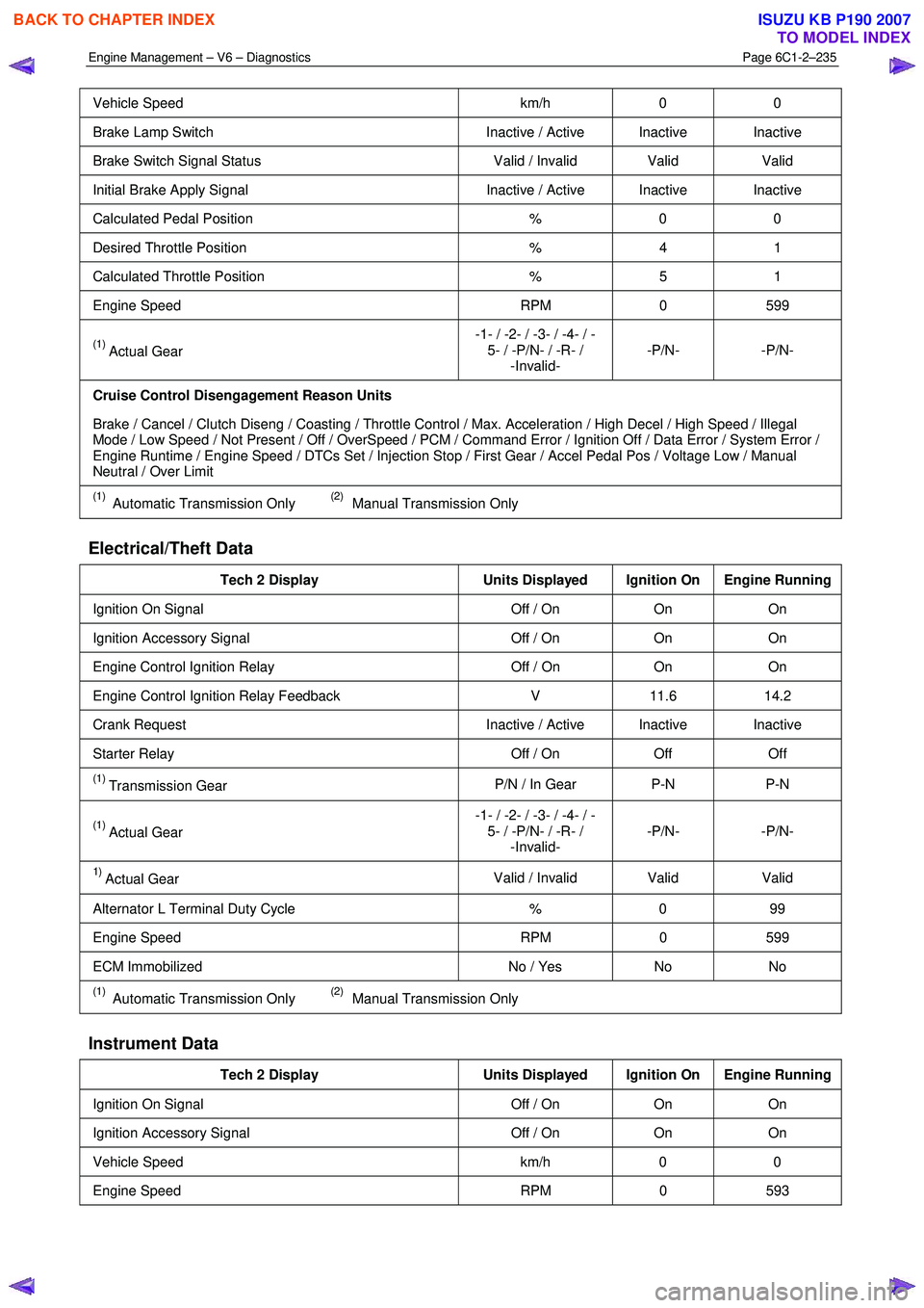
Engine Management – V6 – Diagnostics Page 6C1-2–235
Vehicle Speed km/h 0 0
Brake Lamp Switch Inactive / Active Inactive Inactive
Brake Switch Signal Status Valid / Invalid Valid Valid
Initial Brake Apply Signal Inactive / Active Inactive Inactive
Calculated Pedal Position % 0 0
Desired Throttle Position % 4 1
Calculated Throttle Position % 5 1
Engine Speed RPM 0 599
(1) Actual Gear -1- / -2- / -3- / -4- / -
5- / -P/N- / -R- / -Invalid- -P/N- -P/N-
Cruise Control Disengagement Reason Units
Brake / Cancel / Clutch Diseng / Coasting / Throttle Control / Max. Acceleration / High Decel / High Speed / Illegal
Mode / Low Speed / Not Present / Off / OverSpeed / PCM / Command Error / Ignition Off / Data Error / System Error /
Engine Runtime / Engine Speed / DTCs Set / Injection Stop / First Gear / Accel Pedal Pos / Voltage Low / Manual
Neutral / Over Limit
(1) Automatic Transmission Only (2) Manual Transmission Only
Electrical/Theft Data
Tech 2 Display Units Displayed Ignition On Engine Running
Ignition On Signal Off / On On On
Ignition Accessory Signal Off / On On On
Engine Control Ignition Relay Off / On On On
Engine Control Ignition Relay Feedback V 11.6 14.2
Crank Request Inactive / Active Inactive Inactive
Starter Relay Off / On Off Off
(1) Transmission Gear P/N / In Gear P-N P-N
(1) Actual Gear -1- / -2- / -3- / -4- / -
5- / -P/N- / -R- / -Invalid- -P/N- -P/N-
1) Actual Gear
Valid / Invalid Valid
Valid
Alternator L Terminal Duty Cycle % 0 99
Engine Speed RPM 0 599
ECM Immobilized No / Yes No No
(1) Automatic Transmission Only (2) Manual Transmission Only
Instrument Data
Tech 2 Display Units Displayed Ignition On Engine Running
Ignition On Signal Off / On On On
Ignition Accessory Signal Off / On On On
Vehicle Speed km/h 0 0
Engine Speed RPM 0 593
BACK TO CHAPTER INDEX
TO MODEL INDEX
ISUZU KB P190 2007
Page 3514 of 6020
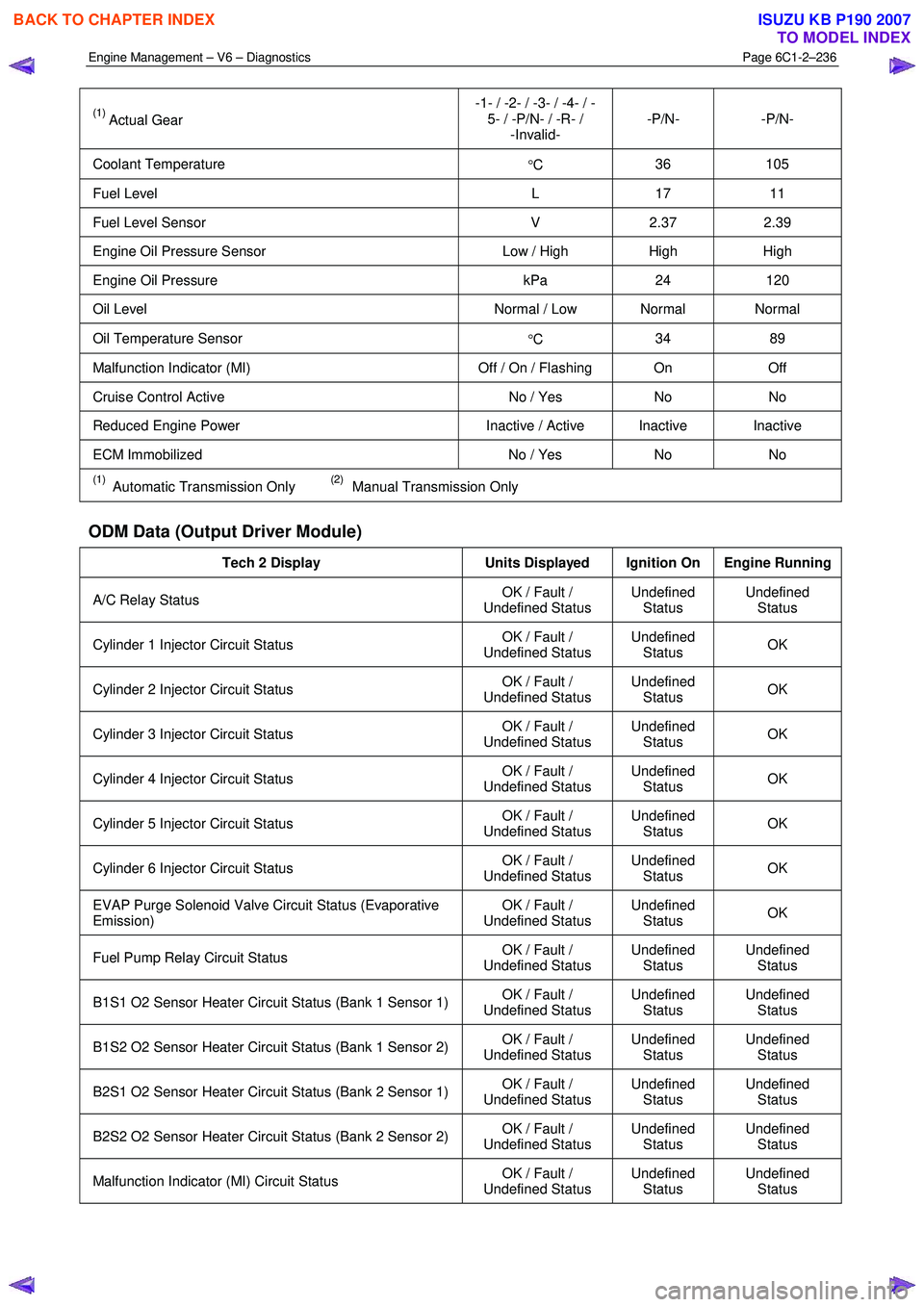
Engine Management – V6 – Diagnostics Page 6C1-2–236
(1) Actual Gear -1- / -2- / -3- / -4- / -
5- / -P/N- / -R- / -Invalid- -P/N- -P/N-
Coolant Temperature
°C 36 105
Fuel Level
L 17 11
Fuel Level Sensor V 2.37 2.39
Engine Oil Pressure Sensor Low / High High High
Engine Oil Pressure kPa 24 120
Oil Level Normal / Low Normal Normal
Oil Temperature Sensor
°C 34 89
Malfunction Indicator (MI)
Off / On / Flashing On Off
Cruise Control Active No / Yes No No
Reduced Engine Power Inactive / Active Inactive Inactive
ECM Immobilized No / Yes No No
(1) Automatic Transmission Only (2) Manual Transmission Only
ODM Data (Output Driver Module)
Tech 2 Display Units Displayed Ignition On Engine Running
A/C Relay Status OK / Fault /
Undefined Status Undefined
Status Undefined
Status
Cylinder 1 Injector Circuit Status OK / Fault /
Undefined Status Undefined
Status OK
Cylinder 2 Injector Circuit Status
OK / Fault /
Undefined Status Undefined
Status OK
Cylinder 3 Injector Circuit Status
OK / Fault /
Undefined Status Undefined
Status OK
Cylinder 4 Injector Circuit Status
OK / Fault /
Undefined Status Undefined
Status OK
Cylinder 5 Injector Circuit Status
OK / Fault /
Undefined Status Undefined
Status OK
Cylinder 6 Injector Circuit Status
OK / Fault /
Undefined Status Undefined
Status OK
EVAP Purge Solenoid Valve Circuit Status (Evaporative
Emission) OK / Fault /
Undefined Status Undefined
Status OK
Fuel Pump Relay Circuit Status
OK / Fault /
Undefined Status Undefined
Status Undefined
Status
B1S1 O2 Sensor Heater Circuit Status (Bank 1 Sensor 1) OK / Fault /
Undefined Status Undefined
Status Undefined
Status
B1S2 O2 Sensor Heater Circuit Status (Bank 1 Sensor 2) OK / Fault /
Undefined Status Undefined
Status Undefined
Status
B2S1 O2 Sensor Heater Circuit Status (Bank 2 Sensor 1) OK / Fault /
Undefined Status Undefined
Status Undefined
Status
B2S2 O2 Sensor Heater Circuit Status (Bank 2 Sensor 2) OK / Fault /
Undefined Status Undefined
Status Undefined
Status
Malfunction Indicator (MI) Circuit Status OK / Fault /
Undefined Status Undefined
Status Undefined
Status
BACK TO CHAPTER INDEX
TO MODEL INDEX
ISUZU KB P190 2007
Page 3515 of 6020
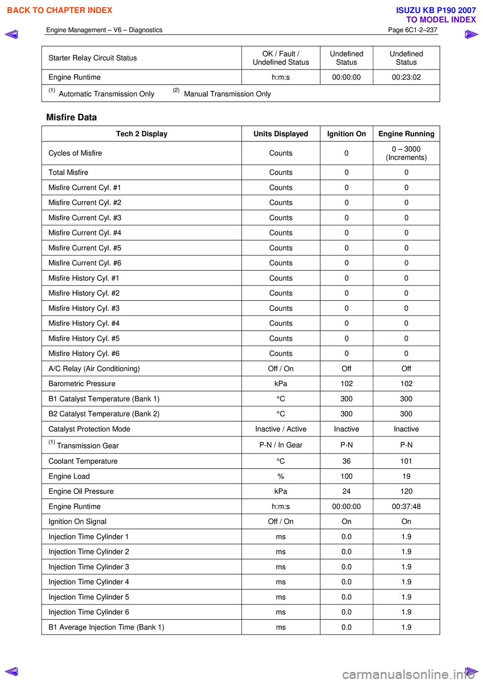
Engine Management – V6 – Diagnostics Page 6C1-2–237
Starter Relay Circuit Status OK / Fault /
Undefined Status Undefined
Status Undefined
Status
Engine Runtime h:m:s 00:00:00 00:23:02
(1) Automatic Transmission Only (2) Manual Transmission Only
Misfire Data
Tech 2 Display Units Displayed Ignition On Engine Running
Cycles of Misfire Counts 0 0 – 3000
(Increments)
Total Misfire Counts 0 0
Misfire Current Cyl. #1 Counts 0 0
Misfire Current Cyl. #2 Counts 0 0
Misfire Current Cyl. #3 Counts 0 0
Misfire Current Cyl. #4 Counts 0 0
Misfire Current Cyl. #5 Counts 0 0
Misfire Current Cyl. #6 Counts 0 0
Misfire History Cyl. #1 Counts 0 0
Misfire History Cyl. #2 Counts 0 0
Misfire History Cyl. #3 Counts 0 0
Misfire History Cyl. #4 Counts 0 0
Misfire History Cyl. #5 Counts 0 0
Misfire History Cyl. #6 Counts 0 0
A/C Relay (Air Conditioning) Off / On Off Off
Barometric Pressure kPa 102 102
B1 Catalyst Temperature (Bank 1) °C 300 300
B2 Catalyst Temperature (Bank 2) °C 300 300
Catalyst Protection Mode Inactive / Active Inactive Inactive
(1) Transmission Gear P-N / In Gear P-N P-N
Coolant Temperature
°C 36 101
Engine Load % 100 19
Engine Oil Pressure kPa 24 120
Engine Runtime h:m:s 00:00:00 00:37:48
Ignition On Signal Off / On On On
Injection Time Cylinder 1 ms 0.0 1.9
Injection Time Cylinder 2 ms 0.0 1.9
Injection Time Cylinder 3 ms 0.0 1.9
Injection Time Cylinder 4 ms 0.0 1.9
Injection Time Cylinder 5 ms 0.0 1.9
Injection Time Cylinder 6 ms 0.0 1.9
B1 Average Injection Time (Bank 1) ms 0.0 1.9
BACK TO CHAPTER INDEX
TO MODEL INDEX
ISUZU KB P190 2007
Page 3516 of 6020
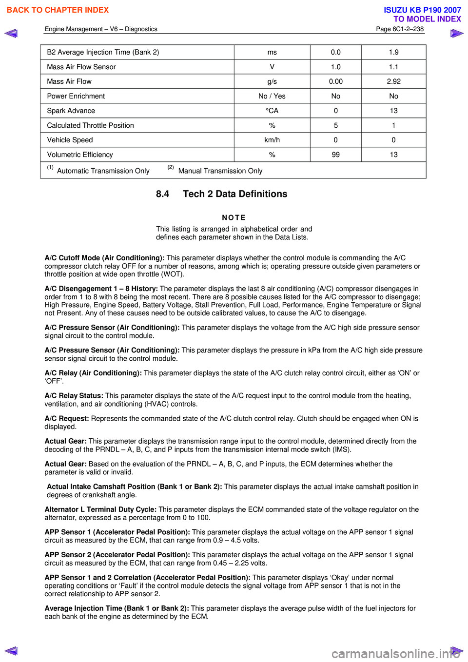
Engine Management – V6 – Diagnostics Page 6C1-2–238
B2 Average Injection Time (Bank 2) ms 0.0 1.9
Mass Air Flow Sensor V 1.0 1.1
Mass Air Flow g/s 0.00 2.92
Power Enrichment No / Yes No No
Spark Advance °CA 0 13
Calculated Throttle Position % 5 1
Vehicle Speed km/h 0 0
Volumetric Efficiency % 99 13
(1) Automatic Transmission Only (2) Manual Transmission Only
8.4 Tech 2 Data Definitions
NOTE
This listing is arranged in alphabetical order and
defines each parameter shown in the Data Lists.
A/C Cutoff Mode (Air Conditioning): This parameter displays whether the control module is commanding the A/C
compressor clutch relay OFF for a number of reasons, among which is; operating pressure outside given parameters or
throttle position at wide open throttle (W OT).
A/C Disengagement 1 – 8 History: The parameter displays the last 8 air conditioning (A/C) compressor disengages in
order from 1 to 8 with 8 being the most recent. There are 8 possible causes listed for the A/C compressor to disengage;
High Pressure, Engine Speed, Battery Voltage, Stall Prevention, Full Load, Performance, Engine Temperature or Signal
not Present. Any of these causes need to be outside calibrated values, to cause the A/C to disengage.
A/C Pressure Sensor (Air Conditioning): This parameter displays the voltage from the A/C high side pressure sensor
signal circuit to the control module.
A/C Pressure Sensor (Air Conditioning): This parameter displays the pressure in kPa from the A/C high side pressure
sensor signal circuit to the control module.
A/C Relay (Air Conditioning): This parameter displays the state of the A/C clutch relay control circuit, either as ‘ON’ or
‘OFF’.
A/C Relay Status: This parameter displays the state of the A/C request input to the control module from the heating,
ventilation, and air conditioning (HVAC) controls.
A/C Request: Represents the commanded state of the A/C clutch control relay. Clutch should be engaged when ON is
displayed.
Actual Gear: This parameter displays the transmission range input to the control module, determined directly from the
decoding of the PRNDL – A, B, C, and P inputs from the transmission internal mode switch (IMS).
Actual Gear: Based on the evaluation of the PRNDL – A, B, C, and P inputs, the ECM determines whether the
parameter is valid or invalid.
Actual Intake Camshaft Position (Bank 1 or Bank 2): This parameter displays the actual intake camshaft position in
degrees of crankshaft angle.
Alternator L Terminal Duty Cycle: This parameter displays the ECM commanded state of the voltage regulator on the
alternator, expressed as a percentage from 0 to 100.
APP Sensor 1 (Accelerator Pedal Position): This parameter displays the actual voltage on the APP sensor 1 signal
circuit as measured by the ECM, that can range from 0.9 – 4.5 volts.
APP Sensor 2 (Accelerator Pedal Position): This parameter displays the actual voltage on the APP sensor 1 signal
circuit as measured by the ECM, that can range from 0.45 – 2.25 volts.
APP Sensor 1 and 2 Correlation (Accelerator Pedal Position): This parameter displays ‘Okay’ under normal
operating conditions or ‘Fault’ if the control module detects the signal voltage from APP sensor 1 that is not in the
correct relationship to APP sensor 2.
Average Injection Time (Bank 1 or Bank 2): This parameter displays the average pulse width of the fuel injectors for
each bank of the engine as determined by the ECM.
BACK TO CHAPTER INDEX
TO MODEL INDEX
ISUZU KB P190 2007