2007 ISUZU KB P190 engine
[x] Cancel search: enginePage 3213 of 6020
Fuel System – V6 Page 6C – 11
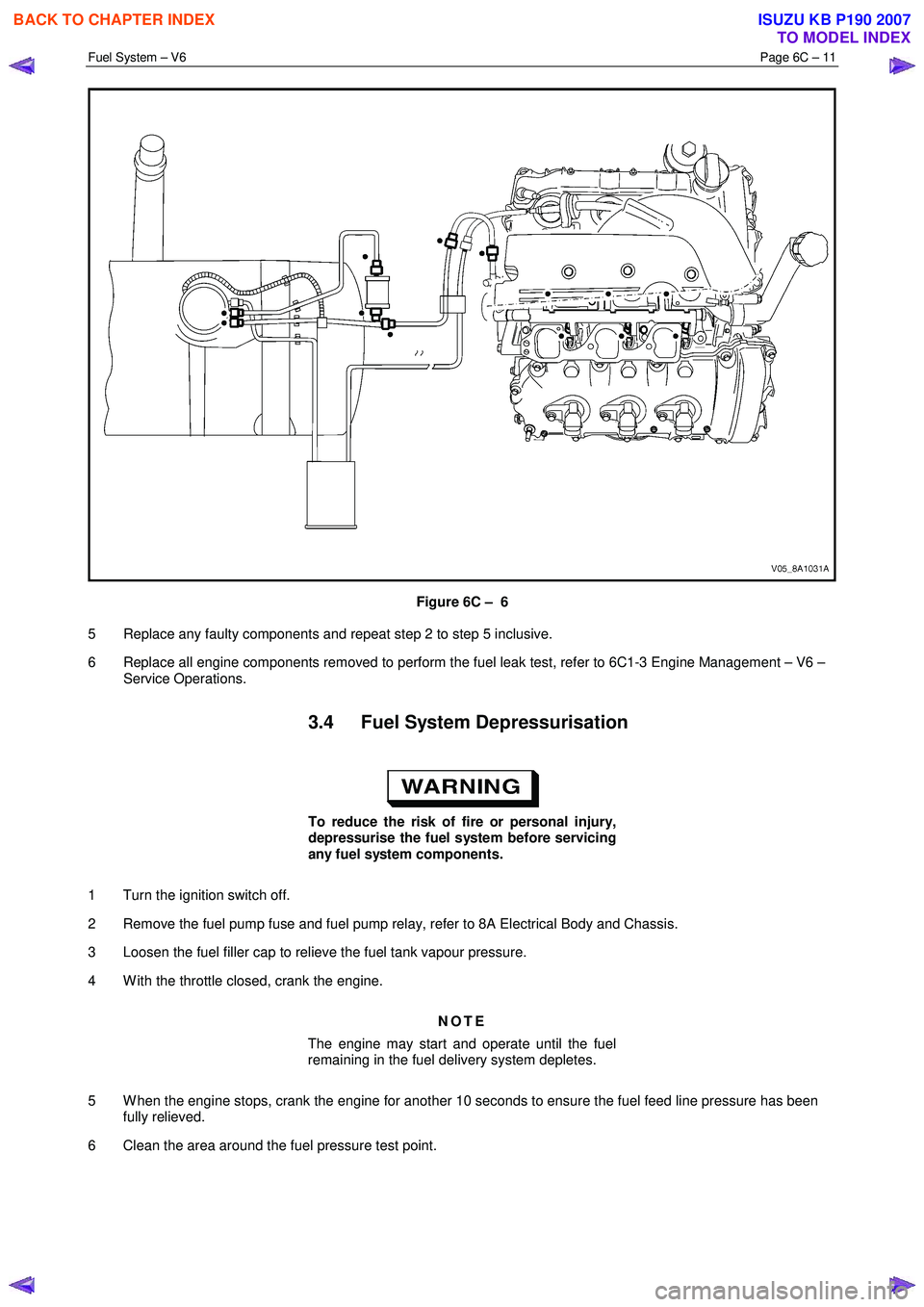
Figure 6C – 6
5 Replace any faulty components and repeat step 2 to step 5 inclusive.
6 Replace all engine components removed to perform the fuel leak test, refer to 6C1-3 Engine Management – V6 – Service Operations.
3.4 Fuel System Depressurisation
To reduce the risk of fire or personal injury,
depressurise the fuel system before servicing
any fuel system components.
1 Turn the ignition switch off.
2 Remove the fuel pump fuse and fuel pump relay, refer to 8A Electrical Body and Chassis.
3 Loosen the fuel filler cap to relieve the fuel tank vapour pressure.
4 W ith the throttle closed, crank the engine.
NOTE
The engine may start and operate until the fuel
remaining in the fuel delivery system depletes.
5 W hen the engine stops, crank the engine for another 10 seconds to ensure the fuel feed line pressure has been fully relieved.
6 Clean the area around the fuel pressure test point.
BACK TO CHAPTER INDEX
TO MODEL INDEX
ISUZU KB P190 2007
Page 3214 of 6020
Fuel System – V6 Page 6C – 12
A small amount of fuel may be released when
pressing on the Schrader valve. Cover the
fitting with a shop towel to absorb any fuel
spillage before removing the Schrader valve
sealing cap. Place the soiled towel in an
approved container for disposal.
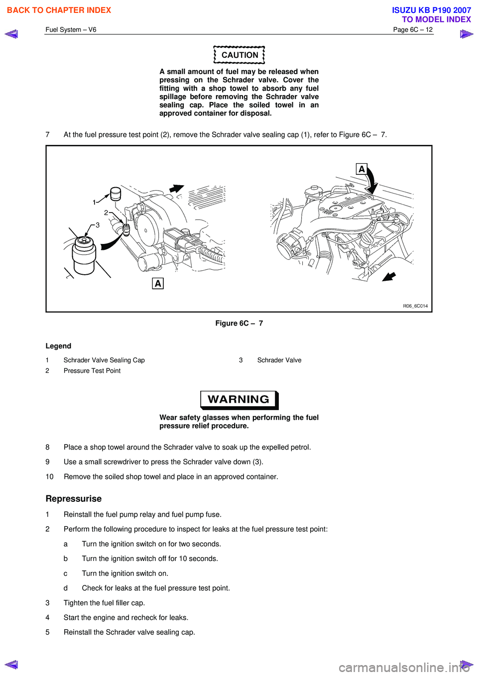
7 At the fuel pressure test point (2), remove the Schrader valve sealing cap (1), refer to Figure 6C – 7.
Figure 6C – 7
Legend
1 Schrader Valve Sealing Cap
2 Pressure Test Point 3 Schrader Valve
Wear safety glasses when performing the fuel
pressure relief procedure.
8 Place a shop towel around the Schrader valve to soak up the expelled petrol.
9 Use a small screwdriver to press the Schrader valve down (3).
10 Remove the soiled shop towel and place in an approved container.
Repressurise
1 Reinstall the fuel pump relay and fuel pump fuse.
2 Perform the following procedure to inspect for leaks at the fuel pressure test point: a Turn the ignition switch on for two seconds.
b Turn the ignition switch off for 10 seconds.
c Turn the ignition switch on.
d Check for leaks at the fuel pressure test point.
3 Tighten the fuel filler cap.
4 Start the engine and recheck for leaks.
5 Reinstall the Schrader valve sealing cap.
BACK TO CHAPTER INDEX
TO MODEL INDEX
ISUZU KB P190 2007
Page 3215 of 6020

Fuel System – V6 Page 6C – 13
4 Service Operations
4.1 Fuel Lines And Quick Connect Fittings
Description
The fuel line connector fittings contain the following
components:
1 O-rings
2 Fuel line port
3 Connector
4 Plastic fuel line tube
Figure 6C – 8
Leak Test and Inspection
1. Turn the ignition key to the ON position and ensure the fuel pump runs for a short time by listening for the pump start up sound. The fuel pressure will increase when the fuel pump is actuated.
2 Perform a preliminary check of the system by inspecting the system for any leaks around the connections and fittings.
3 Perform steps 1 and 2 several times.
4 If the preliminary check of the system produces no leaks, start the engine and check the system again for any sign of leaks around the connections and lines.
Ensure all service precautions have been
observed prior to removing any connector
fittings.
BACK TO CHAPTER INDEX
TO MODEL INDEX
ISUZU KB P190 2007
Page 3217 of 6020
Fuel System – V6 Page 6C – 15
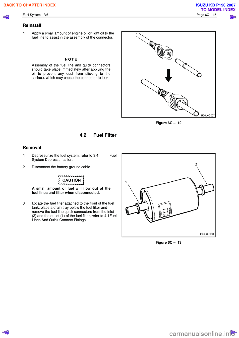
Reinstall
1 Apply a small amount of engine oil or light oil to the
fuel line to assist in the assembly of the connector.
NOTE
Assembly of the fuel line and quick connectors
should take place immediately after applying the
oil to prevent any dust from sticking to the
surface, which may cause the connector to leak.
Figure 6C – 12
4.2 Fuel Filter
Removal
1 Depressurize the fuel system, refer to 3.4 Fuel
System Depressurisation.
2 Disconnect the battery ground cable.
A small amount of fuel will flow out of the
fuel lines and filter when disconnected.
3 Locate the fuel filter attached to the front of the fuel tank, place a drain tray below the fuel filter and
remove the fuel line quick connectors from the inlet
(2) and the outlet (1) of the fuel filter, refer to 4.1 Fuel
Lines And Quick Connect Fittings.
Figure 6C – 13
BACK TO CHAPTER INDEX
TO MODEL INDEX
ISUZU KB P190 2007
Page 3225 of 6020
Fuel System – V6 Page 6C – 23
4.5 Modular Fuel Pump and Sender
Assembly
NOTE
If the modular fuel pump and sender assembly
develops a fault it must be replaced as a
complete unit. The only serviced parts are the
retainer locking ring and the O-ring seal.
Remove
• A depressurised fuel system contains fuel
in the fuel filter and fuel lines that can be
spilled during service operations.
• Fuel vapour remains in the fuel tank even
when completely empty. Seal all openings
in the fuel tank using suitable material or a
plastic plug. Ensure no naked flames or
other ignition sources are nearby. Ensure
all cellular phones (and transmission
devices that may cause any metal objects
to become unintentional receiving
antennas) are switched off.
• Place a dry chemical (Class B) fire
extinguisher nearby before performing any
on-vehicle service procedures. Failure to
follow these precautions may result in
personal injury.
• Wear safety glasses when using
compressed air. Do not blow compressed
air directly onto any body part.
1 Remove the fuel pump relay, refer to 8A Engine Body and Chassis.
2 Remove the fuel tank assembly from the vehicle, refer to 4.4 Fuel Tank.
Before proceeding, clean all traces of dirt and
other foreign material from the top of the fuel
tank, near the modular fuel pump and sender
assembly.
3 Use compressed air to ensure all dirt and foreign materials are removed from all fuel connections before disconnecting the parts.
Fuel can spill from the disconnected modular
fuel pump and sender assembly.
BACK TO CHAPTER INDEX
TO MODEL INDEX
ISUZU KB P190 2007
Page 3238 of 6020
Fuel System – V6 Page 6C – 36
Bell Housing Fuel Lines
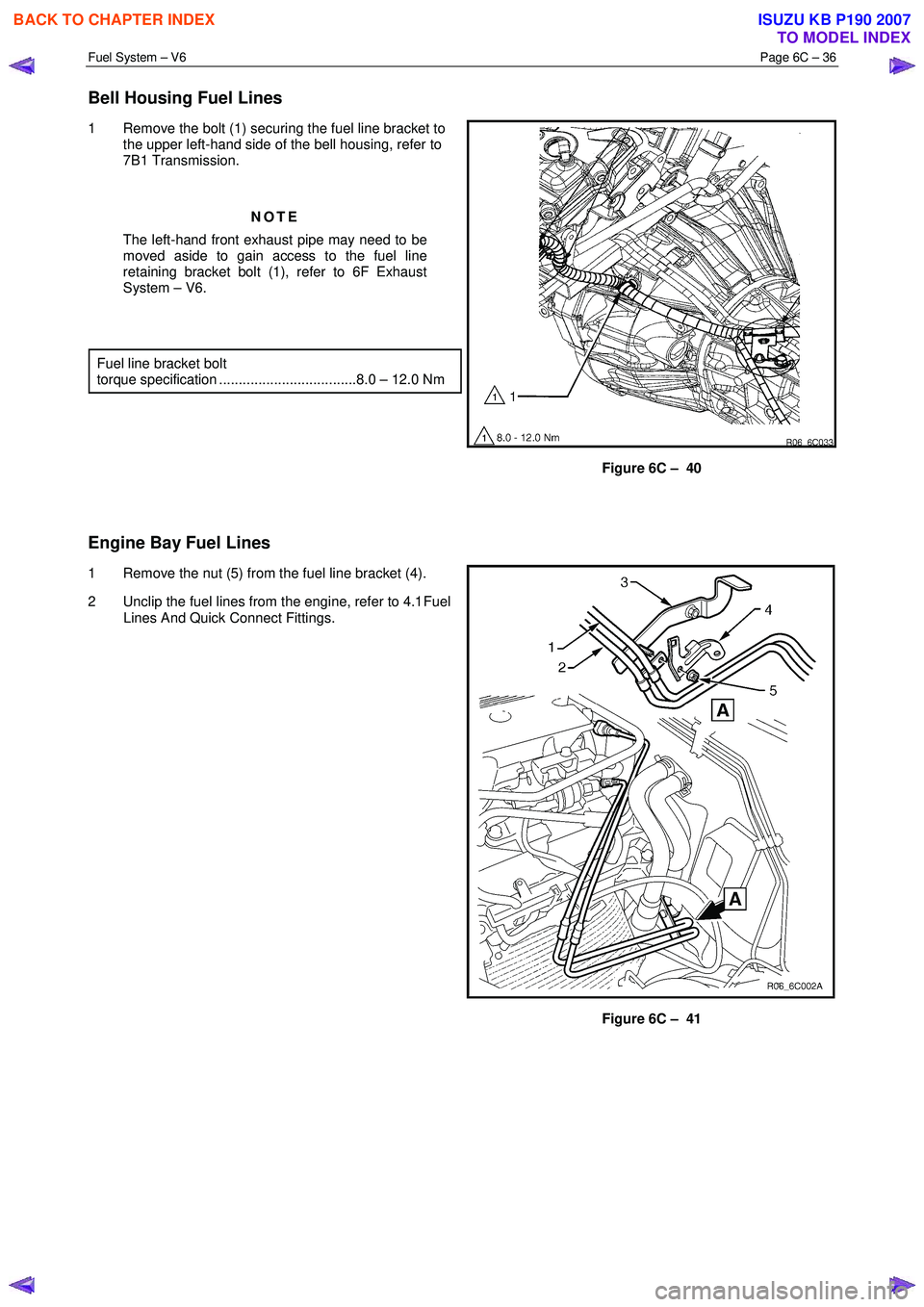
1 Remove the bolt (1) securing the fuel line bracket to
the upper left-hand side of the bell housing, refer to
7B1 Transmission.
NOTE
The left-hand front exhaust pipe may need to be
moved aside to gain access to the fuel line
retaining bracket bolt (1), refer to 6F Exhaust
System – V6.
Fuel line bracket bolt
torque specification ...................................8.0 – 12.0 Nm
Figure 6C – 40
Engine Bay Fuel Lines
1 Remove the nut (5) from the fuel line bracket (4).
2 Unclip the fuel lines from the engine, refer to 4.1 Fuel
Lines And Quick Connect Fittings.
Figure 6C – 41
BACK TO CHAPTER INDEX
TO MODEL INDEX
ISUZU KB P190 2007
Page 3240 of 6020
Fuel System – V6 Page 6C – 38
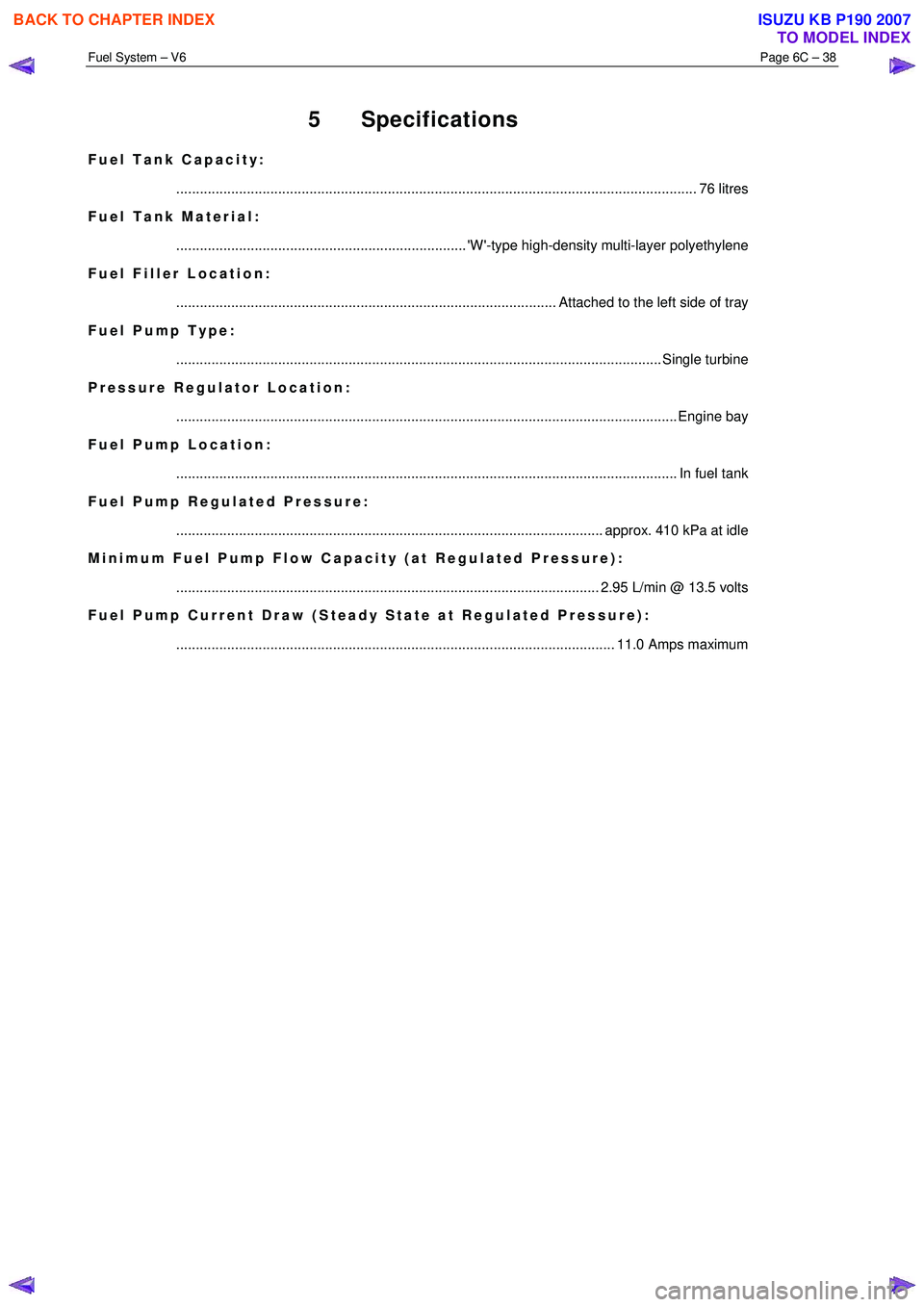
5 Specifications
Fuel Tank Capacity:
............................................................................................................................... ...... 76 litres
Fuel Tank Material:
.......................................................................... 'W '-type high-density multi-layer polyethylene
Fuel Filler Location:
................................................................................................. Attached to the left side of t ray
Fuel Pump Type:
............................................................................................................................ Sin gle turbine
Pressure Regulator Location:
............................................................................................................................... . Engine bay
Fuel Pump Location:
............................................................................................................................... . In fuel tank
Fuel Pump Regulated Pressure:
............................................................................................................. approx. 410 kPa at idle
Minimum Fuel Pump Flow Capacity (at Regulated Pressure):
............................................................................................................ 2.95 L/min @ 13.5 v olts
Fuel Pump Current Draw (Steady State at Regulated Pressure):
................................................................................................................ 11.0 Amps maxim um
BACK TO CHAPTER INDEX
TO MODEL INDEX
ISUZU KB P190 2007
Page 3243 of 6020
Engine Management – V6 – General Information Page 6C1-1–1
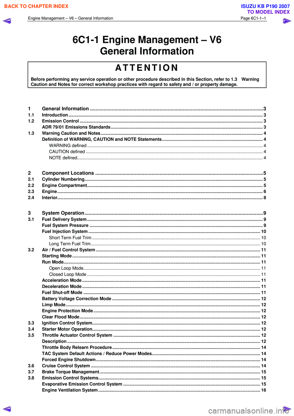
6C1-1 Engine Management – V6
General Information
ATTENTION
Before performing any service operation or other procedure described in this Section, refer to 1.3 Warning
Caution and Notes for correct workshop practices with regard to safety and / or property damage.
1 General Information ............................................................................................................ ...................3
1.1 Introduction ............................................................................................................................................................ 3
1.2 Emission Control ................................................................................................................................................... 3
ADR 79/01 Emissions Standards .......................................................................................................................... 3
1.3 Warning Caution and Notes .................................................................................................................................. 4
Definition of WARNING, CAUTION and NOTE Statements ............................................................................. .... 4
WARNING defined ............................................................................................................................................. 4
CAUTION defined .............................................................................................................................................. 4
NOTE defined..................................................................................................................................................... 4
2 Component Locations ............................................................................................................ ...............5
2.1 Cylinder Numbering............................................................................................................................................... 5
2.2 Engine Compartment............................................................................................................................................. 5
2.3 Engine ..................................................................................................................................................................... 6
2.4 Interior..................................................................................................................................................................... 8
3 System Operation ...................................................................................................................................9
3.1 Fuel Delivery System ............................................................................................................................................. 9
Fuel System Pressure ........................................................................................................... ................................ 9
Fuel Injection System .......................................................................................................................................... 10
Short Term Fuel Trim ....................................................................................................................................... 10
Long Term Fuel Trim ........................................................................................................................................ 10
3.2 Air / Fuel Control System ...................................................................................................... .............................. 11
Starting Mode ....................................................................................................................................................... 11
Run Mode.............................................................................................................................................................. 11
Open Loop Mode................................................................................................................. ............................. 11
Closed Loop Mode ............................................................................................................... ............................ 11
Acceleration Mode .............................................................................................................. ................................. 11
Deceleration Mode ............................................................................................................................................... 11
Fuel Shut-off Mode .............................................................................................................................................. 11
Battery Voltage Correction Mode ................................................................................................ ....................... 12
Limp Mode ............................................................................................................................................................ 12
Engine Protection Mode ......................................................................................................... ............................. 12
Clear Flood Mode ................................................................................................................................................. 12
3.3 Ignition Control System........................................................................................................ ............................... 12
3.4 Starter Motor Operation....................................................................................................................................... 12
3.5 Throttle Actuator Control System ............................................................................................... ....................... 12
Description ........................................................................................................................................................... 12
Throttle Body Relearn Procedure ....................................................................................................................... 14
TAC System Default Actions / Reduce Power Modes................................................................................ ....... 14
Forced Engine Shutdown .................................................................................................................................... 14
3.6 Cruise Control System ........................................................................................................................................ 14
3.7 Brake Torque Management ........................................................................................................ ......................... 15
3.8 Emission Control Systems.................................................................................................................................. 15
Evaporative Emission Control System ............................................................................................ .................. 15
Engine Ventilation System .................................................................................................................................. 16
BACK TO CHAPTER INDEX
TO MODEL INDEX
ISUZU KB P190 2007