2007 ISUZU KB P190 oil capacity
[x] Cancel search: oil capacityPage 2092 of 6020
6A-78 ENGINE MECHANICAL (C24SE)
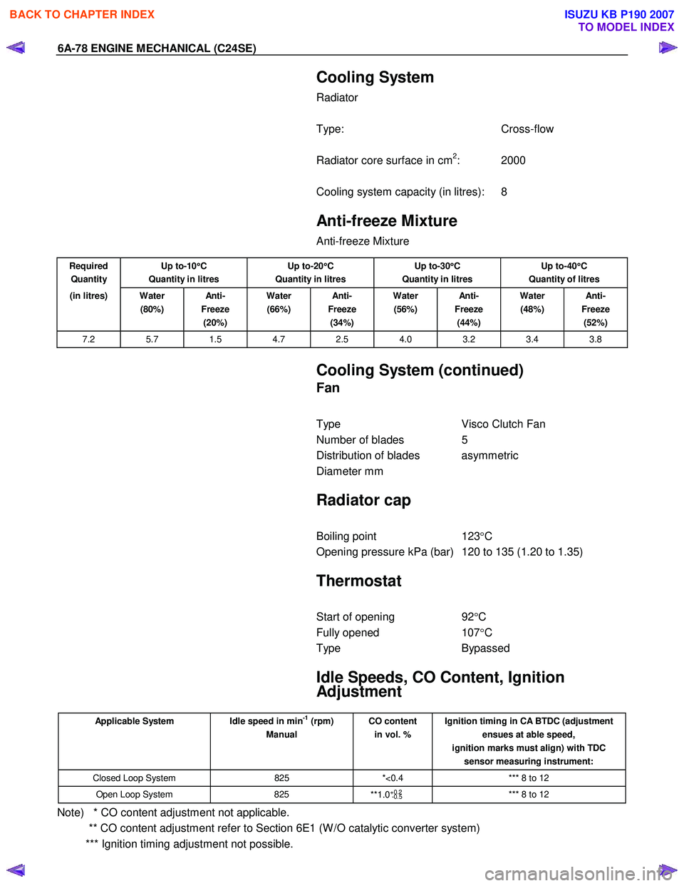
Cooling System
Radiator
Type: Cross-flow
Radiator core surface in cm
2: 2000
Cooling system capacity (in litres): 8
Anti-freeze Mixture
Anti-freeze Mixture
Required
Quantity Up to-10
°
°°
°
C
Quantity in litres Up to-20
°
°°
°
C
Quantity in litres Up to-30
°
°°
°
C
Quantity in litres Up to-40
°
°°
°
C
Quantity of litres
(in litres) Water (80%) An ti -
Freeze (20%) Water
(66%) An ti -
Freeze (34%) Water
(56%) An ti -
Freeze (44%) Water
(48%) An ti -
Freeze (52%)
7.2 5.7 1.5 4.7 2.5 4.0 3.2 3.4 3.8
Cooling System (continued)
Fan
Type Visco Clutch Fan
Number of blades 5
Distribution of blades asymmetric
Diameter mm
Radiator cap
Boiling point 123°C
Opening pressure kPa (bar) 120 to 135 (1.20 to 1.35)
Thermostat
Start of opening 92°C
Fully opened 107°C
Type Bypassed
Idle Speeds, CO Content, Ignition
Adjustment
Applicable System Idle speed in min-1 (rpm)
Manual CO content
in vol. % Ignition timing in CA BTDC (adjustment
ensues at able speed,
ignition marks must align) with TDC sensor measuring instrument:
Closed Loop System 825 *<0.4 *** 8 to 12
Open Loop System 825
**1.0+0.2
-0.5 *** 8 to 12
Note) * CO content adjustment not applicable.
** CO content adjustment refer to Section 6E1 (W /O catalytic converter system)
*** Ignition timing adjustment not possible.
BACK TO CHAPTER INDEX
TO MODEL INDEX
ISUZU KB P190 2007
Page 2202 of 6020
6E–32 ENGINE DRIVEABILITY AND EMISSIONS
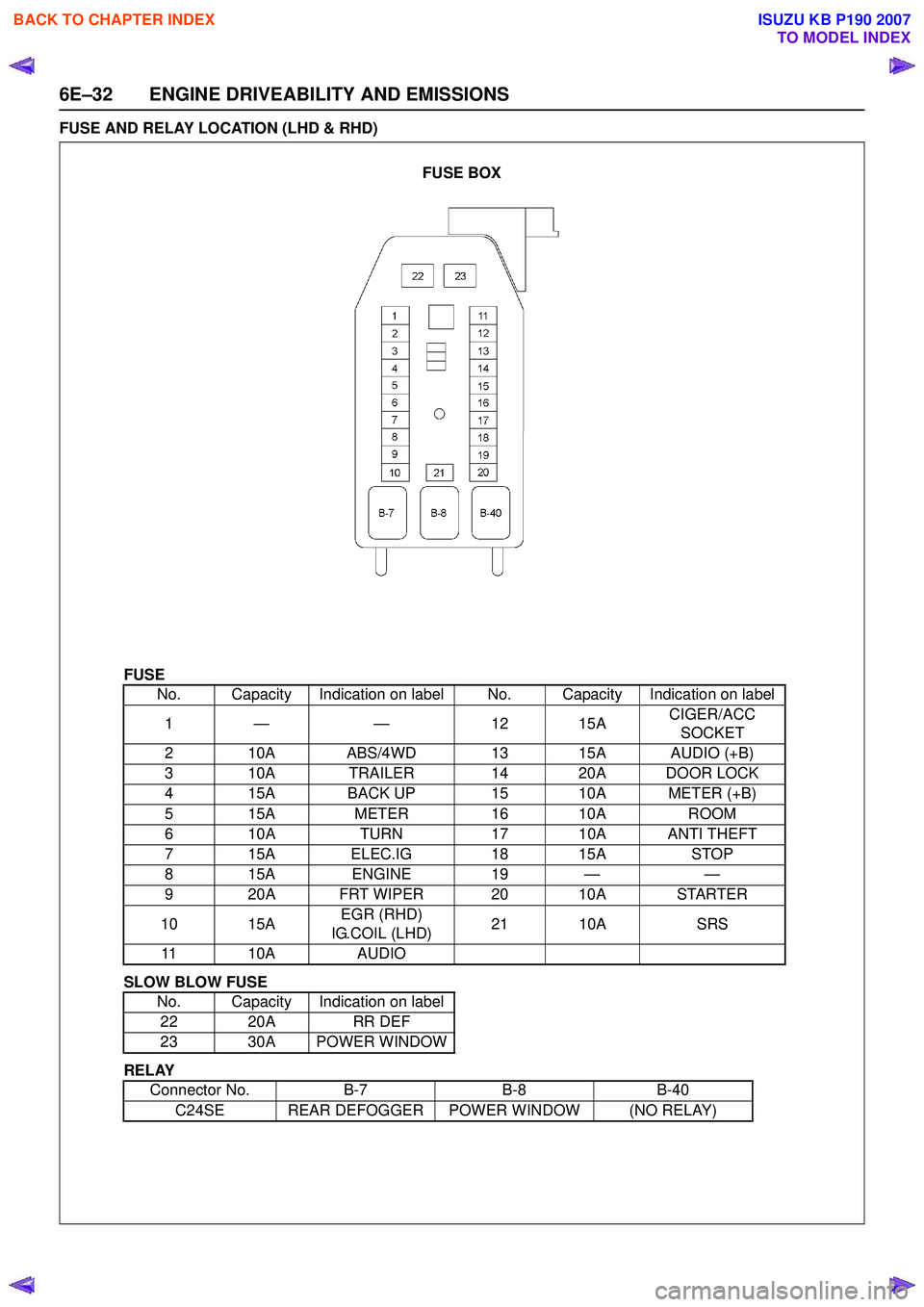
FUSE AND RELAY LOCATION (LHD & RHD)
FUSE
SLOW BLOW FUSE
RELAY No. Capacity Indication on label No. Capacity Indication on label
1— — 1 215A CIGER/ACC
SOCKET
2 10A ABS/4WD 13 15A AUDIO (+B)
3 10A TRAILER 14 20A DOOR LOCK
4 15A BACK UP 15 10A METER (+B)
5 15A METER16 10A ROOM
6 10A TURN17 10A ANTI THEFT
7 15A ELEC.IG 18 15ASTOP
815A ENGINE 19 — —
9 20A FRT WIPER 20 10A STARTER
10 15A EGR (RHD)
IG.COIL (LHD) 21 10A
SRS
11 10A AUDIO
No. Capacity Indication on label 22 20A RR DEF
23 30A POWER WINDOW
Connector No. B-7B-8B-40
C24SE REAR DEFOGGER POWER WINDOW (NO RELAY)
FUSE BOX
BACK TO CHAPTER INDEX
TO MODEL INDEX
ISUZU KB P190 2007
Page 2534 of 6020
Engine Mechanical – V6 Page 6A1–55
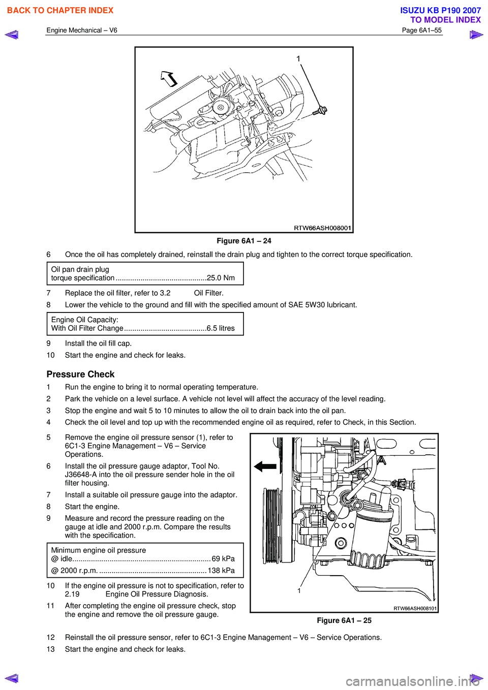
Figure 6A1 – 24
6 Once the oil has completely drained, reinstall the drain plug and tighten to the correct torque specification.
Oil pan drain plug
torque specification ............................................25.0 Nm
7 Replace the oil filter, refer to 3.2 Oil Filter.
8 Lower the vehicle to the ground and fill with the specified amount of SAE 5W 30 lubricant.
Engine Oil Capacity:
With Oil Filter Change ........................................6.5 litres
9 Install the oil fill cap.
10 Start the engine and check for leaks.
Pressure Check
1 Run the engine to bring it to normal operating temperature.
2 Park the vehicle on a level surface. A vehicle not level will affect the accuracy of the level reading.
3 Stop the engine and wait 5 to 10 minutes to allow the oil to drain back into the oil pan.
4 Check the oil level and top up with the recommended engine oil as required, refer to Check, in this Section.
5 Remove the engine oil pressure sensor (1), refer to 6C1-3 Engine Management – V6 – Service
Operations.
6 Install the oil pressure gauge adaptor, Tool No. J36648-A into the oil pressure sender hole in the oil
filter housing.
7 Install a suitable oil pressure gauge into the adaptor.
8 Start the engine.
9 Measure and record the pressure reading on the gauge at idle and 2000 r.p.m. Compare the results
with the specification.
Minimum engine oil pressure
@ idle................................................................... 69 kPa
@ 2000 r.p.m. .................................................... 138 kPa
10 If the engine oil pressure is not to specification, refer to 2.19 Engine Oil Pressure Diagnosis.
11 After completing the engine oil pressure check, stop the engine and remove the oil pressure gauge.
Figure 6A1 – 25
12 Reinstall the oil pressure sensor, refer to 6C1-3 Engine Management – V6 – Service Operations.
13 Start the engine and check for leaks.
BACK TO CHAPTER INDEX
TO MODEL INDEX
ISUZU KB P190 2007
Page 2769 of 6020
Engine Mechanical – V6 Page 6A1–290
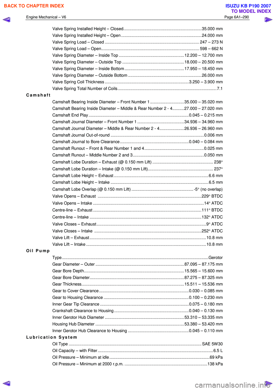
Valve Spring Installed Height – Closed................................................................... 35.000 mm
Valve Spring Installed Height – Open ..................................................................... 24.000 mm
Valve Spring Load – Closed ................................................................................. 247 – 273 N
Valve Spring Load – Open.................................................................................... 598 – 662 N
Valve Spring Diameter – Inside Top ........................................................ 12.200 – 12.700 mm
Valve Spring Diameter – Outside Top ..................................................... 18.000 – 20.500 mm
Valve Spring Diameter – Inside Bottom ................................................... 17.950 – 18.450 mm
Valve Spring Diameter – Outside Bottom ............................................................... 26.000 mm
Valve Spring Coil Thickness ........................................................................ 3.250 – 3.900 mm
Valve Spring Total Number of Coils ..................................................................................... 7.1
Camshaft
Camshaft Bearing Inside Diameter – Front Number 1 ............................. 35.000 – 35.020 mm
Camshaft Bearing Inside Diameter – Middle & Rear Number 2 - 4.......... 27.000 – 27.020 mm
Camshaft End Play ...................................................................................... 0.045 – 0.215 mm
Camshaft Journal Diameter – Front Number 1 ........................................ 34.936 – 34.960 mm
Camshaft Journal Diameter – Middle & Rear Number 2 - 4..................... 26.936 – 26.960 mm
Camshaft Journal Out-of-round ................................................................................ 0.006 mm
Camshaft Journal to Bore Clearance ........................................................... 0.040 – 0.084 mm
Camshaft Runout – Front & Rear Number 1 and 4 ................................................... 0.025 mm
Camshaft Runout – Middle Number 2 and 3............................................................ .0.050 mm
Camshaft Lobe Duration – Exhaust (@ 0.150 mm Lift) .................................................... 238 °
Camshaft Lobe Duration – Intake (@ 0.150 mm Lift)........................................................ 237 °
Camshaft Lobe Height – Exhaust ................................................................................. 6.6 mm
Camshaft Lobe Height – Intake .................................................................................... 6.5 mm
Camshaft Lobe Overlap (@ 0.150 mm Lift) ..................................................... -5 ° (no overlap)
Valve Opens – Exhaust .........................................................................................229 ° BTDC
Valve Opens – Intake ...............................................................................................14 ° ATDC
Centre-line – Exhaust .............................................................................................111 ° BTDC
Centre-line – Intake ................................................................................................132 ° ATDC
Valve Closes – Exhaust ..............................................................................................9 ° ATDC
Valve Closes – Intake ............................................................................................252 ° ATDC
Valve Lift – Exhaust .................................................................................................... 10.8 mm
Valve Lift – Intake ....................................................................................................... 10.8 mm
Oil Pump
Type........................................................................................................................... ...Gerotor
Gear Diameter – Outer ............................................................................ 87.095 – 87.175 mm
Gear Bore Depth...................................................................................... 15.565 – 15.600 mm
Gear Bore Diameter................................................................................. 87.275 – 87.325 mm
Gear Thickness........................................................................................ 15.511 – 15.536 mm
Gear to Cover Clearance ............................................................................. 0.030 – 0.085 mm
Gear to Housing Clearance ......................................................................... 0.100 – 0.230 mm
Inner Gear Tip Clearance ............................................................................ 0.075 – 0.180 mm
Crankshaft Clearance to Housing ................................................................ 0.040 – 0.130 mm
Inner Gerotor Hub Diameter .................................................................... 53.310 – 53.335 mm
Housing Hub Diameter ............................................................................ 53.380 – 53.420 mm
Inner Gerotor Hub Clearance to Housing .................................................... 0.045 – 0.110 mm
Lubrication System
Oil Type .................................................................................................................. SAE 5 W 30
Oil Capacity – with Filter ................................................................................................... 6. 5 L
Oil Pressure – Minimum at idle ......................................................................................69 kPa
Oil Pressure – Minimum at 2000 r.p.m. .......................................................................138 kPa
BACK TO CHAPTER INDEX
TO MODEL INDEX
ISUZU KB P190 2007
Page 2844 of 6020
Engine Mechanical – V6 Page 6A1–67
Page 6A1–67
Replace
NOTE
• Quicker and more complete draining will
occur if the engine oil is at normal operating
temperature. However, care must be taken to
avoid scalding from the hot oil.
• It recommended the oil filter be changed at
each engine oil change, refer to 3.2 Oil Filter.
1 Remove the oil fill cap.
2 To ensure complete draining of the oil pan, raise the front and rear of the vehicle to maintain a level attitude. If not
using a hoist, support the vehicle with safety stands, refer to Section 0A General Information.
3 Clean any foreign material from around the oil drain pl ug and place a suitable, clean drain tray under the engine.
The oil may be hot. Avoid contact with the oil.
Ensure that eyes and skin are protected.
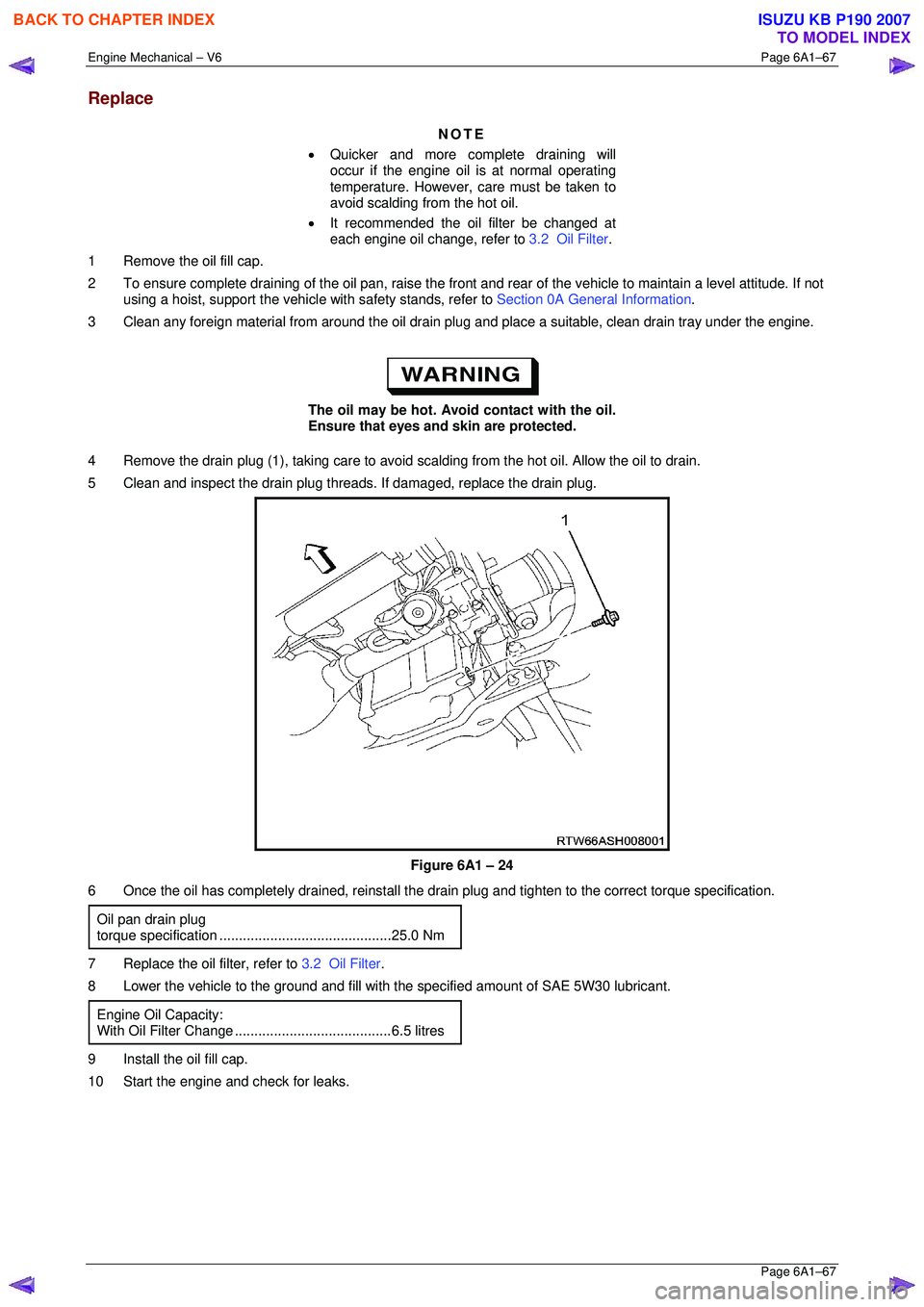
4 Remove the drain plug (1), taking care to avoid sca lding from the hot oil. Allow the oil to drain.
5 Clean and inspect the drain plug threads . If damaged, replace the drain plug.
Figure 6A1 – 24
6 Once the oil has completely drained, reinstall the dr ain plug and tighten to the correct torque specification.
Oil pan drain plug
torque specificat ion ............................................ 25.0 Nm
7 Replace the oil filter, refer to 3.2 Oil Filter.
8 Lower the vehicle to the ground and fill with the specified amount of SAE 5W30 lubricant.
Engine Oil Capacity:
With Oil Filter Change........................................6.5 litres
9 Install the oil fill cap.
10 Start the engine and check for leaks.
BACK TO CHAPTER INDEX
TO MODEL INDEX
ISUZU KB P190 2007
Page 3127 of 6020
Engine Mechanical – V6 Page 6A1–350
Page 6A1–350
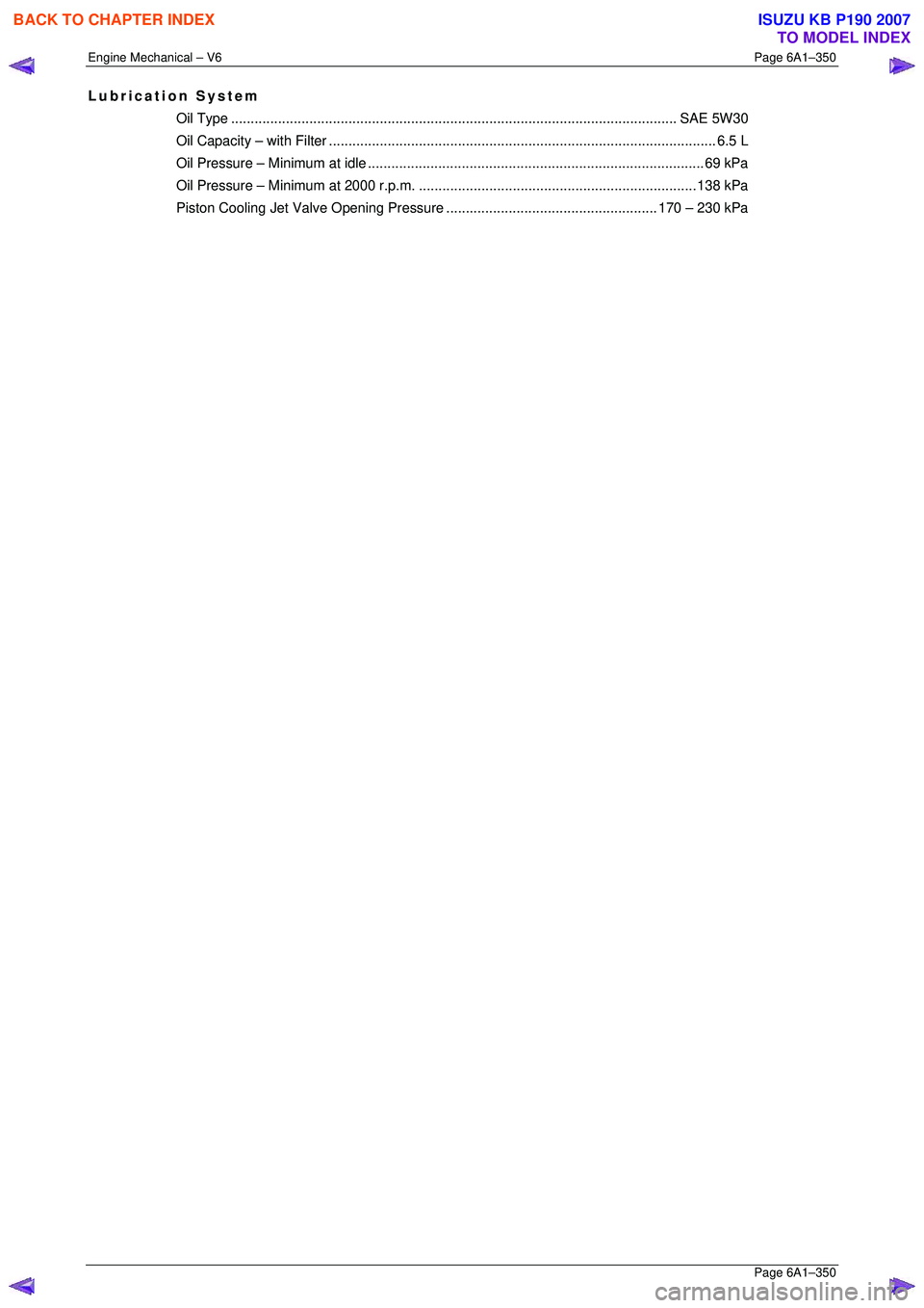
Lubrication System
Oil Type.................................................................................................................. SAE 5 W30
Oil Capacity – with Filter................................................................................................... 6. 5 L
Oil Pressure – Mini mum at idle ......................................................................................69 kPa
Oil Pressure – Minimum at 2000 r.p.m. ....................................................................... 138 kPa
Piston Cooling Jet Valve Op ening Pressure...................................................... 170 – 230 kPa
BACK TO CHAPTER INDEX
TO MODEL INDEX
ISUZU KB P190 2007
Page 3399 of 6020
Engine Management – V6 – Diagnostics Page 6C1-2–121
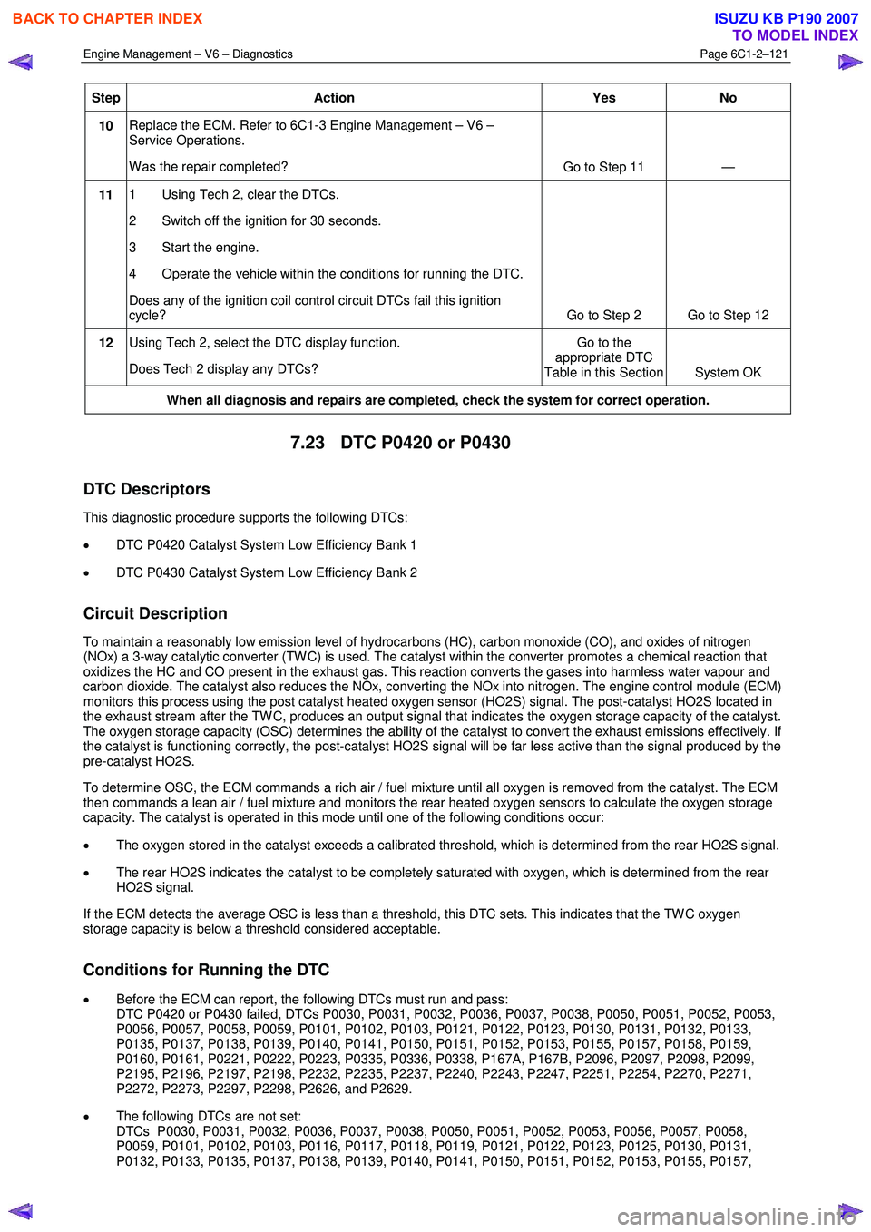
Step Action Yes No
10 Replace the ECM. Refer to 6C1-3 Engine Management – V6 –
Service Operations.
W as the repair completed? Go to Step 11 —
11 1 Using Tech 2, clear the DTCs.
2 Switch off the ignition for 30 seconds.
3 Start the engine.
4 Operate the vehicle within the conditions for running the DTC.
Does any of the ignition coil control circuit DTCs fail this ignition
cycle? Go to Step 2 Go to Step 12
12 Using Tech 2, select the DTC display function.
Does Tech 2 display any DTCs? Go to the
appropriate DTC
Table in this Section System OK
When all diagnosis and repairs are completed, check the system for correct operation.
7.23 DTC P0420 or P0430
DTC Descriptors
This diagnostic procedure supports the following DTCs:
• DTC P0420 Catalyst System Low Efficiency Bank 1
• DTC P0430 Catalyst System Low Efficiency Bank 2
Circuit Description
To maintain a reasonably low emission level of hydrocarbons (HC), carbon monoxide (CO), and oxides of nitrogen
(NOx) a 3-way catalytic converter (TW C) is used. The catalyst within the converter promotes a chemical reaction that
oxidizes the HC and CO present in the exhaust gas. This reaction converts the gases into harmless water vapour and
carbon dioxide. The catalyst also reduces the NOx, converting the NOx into nitrogen. The engine control module (ECM)
monitors this process using the post catalyst heated oxygen sensor (HO2S) signal. The post-catalyst HO2S located in
the exhaust stream after the TW C, produces an output signal that indicates the oxygen storage capacity of the catalyst.
The oxygen storage capacity (OSC) determines the ability of the catalyst to convert the exhaust emissions effectively. If
the catalyst is functioning correctly, the post-catalyst HO2S signal will be far less active than the signal produced by the
pre-catalyst HO2S.
To determine OSC, the ECM commands a rich air / fuel mixture until all oxygen is removed from the catalyst. The ECM
then commands a lean air / fuel mixture and monitors the rear heated oxygen sensors to calculate the oxygen storage
capacity. The catalyst is operated in this mode until one of the following conditions occur:
• The oxygen stored in the catalyst exceeds a calibrated threshold, which is determined from the rear HO2S signal.
• The rear HO2S indicates the catalyst to be completely saturated with oxygen, which is determined from the rear
HO2S signal.
If the ECM detects the average OSC is less than a threshold, this DTC sets. This indicates that the TW C oxygen
storage capacity is below a threshold considered acceptable.
Conditions for Running the DTC
• Before the ECM can report, the following DTCs must run and pass:
DTC P0420 or P0430 failed, DTCs P0030, P0031, P0032, P0036, P0037, P0038, P0050, P0051, P0052, P0053,
P0056, P0057, P0058, P0059, P0101, P0102, P0103, P0121, P0122, P0123, P0130, P0131, P0132, P0133,
P0135, P0137, P0138, P0139, P0140, P0141, P0150, P0151, P0152, P0153, P0155, P0157, P0158, P0159,
P0160, P0161, P0221, P0222, P0223, P0335, P0336, P0338, P167A, P167B, P2096, P2097, P2098, P2099,
P2195, P2196, P2197, P2198, P2232, P2235, P2237, P2240, P2243, P2247, P2251, P2254, P2270, P2271,
P2272, P2273, P2297, P2298, P2626, and P2629.
• The following DTCs are not set:
DTCs P0030, P0031, P0032, P0036, P0037, P0038, P0050, P0051, P0052, P0053, P0056, P0057, P0058,
P0059, P0101, P0102, P0103, P0116, P0117, P0118, P0119, P0121, P0122, P0123, P0125, P0130, P0131,
P0132, P0133, P0135, P0137, P0138, P0139, P0140, P0141, P0150, P0151, P0152, P0153, P0155, P0157,
BACK TO CHAPTER INDEX
TO MODEL INDEX
ISUZU KB P190 2007
Page 3777 of 6020
Automatic Transmission – 4L60E – General Information Page 7C1–17
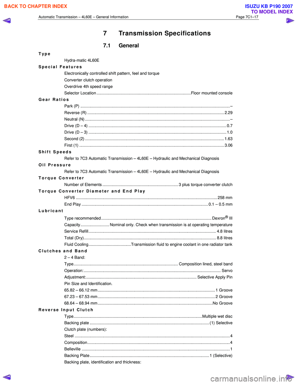
7 Transmission Specifications
7.1 General
Type
Hydra-matic 4L60E
Special Features
Electronically controlled shift pattern, feel and torque
Converter clutch operation
Overdrive 4th speed range
Selector Location ..................................................................................Floor mounted console
Gear Ratios Park (P) ....................................................................................................................... ........... –
Reverse (R) .................................................................................................................... ... 2.29
Neutral (N) .............................................................................................................................. –
Drive (D – 4) .................................................................................................................. ...... 0.7
Drive (D – 3) .................................................................................................................. ...... 1.0
Second (2) ......................................................................................................................... 1.63
First (1) ...................................................................................................................... ........ 3.06
Shift Speeds Refer to 7C3 Automatic Transmission – 4L60E – Hydraulic and Mechanical Diagnosis
Oil Pressure
Refer to 7C3 Automatic Transmission – 4L60E – Hydraulic and Mechanical Diagnosis
Torque Converter
Number of Elements .................................................................. 3 plus torque converter clutch
Torque Converter Diameter and End Play
HFV6 ........................................................................................................................... 258 mm
End Play .............................................................................................................. 0.1 – 0.5 mm
Lubricant
Type recommended ................................................................................................ Dexron
® III
Capacity......................... Nominal only. Check when transmission is at operating temperature
Service Refill ............................................................................................................... 4. 8 litres
Total (Dry)................................................................................................................... 8 .8 litres
Fluid Cooling.....................................Transmission fluid to engine coolant in one radiator tank
Clutches and Band 2 – 4 Band:
Type........................................................................................... Composition lined, steel band
Operation: ..................................................................................................................... .. Servo
Adjustment: ................................................................................................ Selective Apply Pin
Pin Size and Identification.
65.82 – 66.12 mm ...................................................................................................... 1 Groove
67.23 – 67.53 mm ...................................................................................................... 2 Groove
68.64 – 68.94 mm ....................................................................................................No Groove
Reverse Input Clutch Type................................................................................................................Multiple we t disc
Backing plate ........................................................................................................ (1) Select ive
Clutch plate (numbers):
Steel ....................................................................................................................................... 4
Composition............................................................................................................................ 4
Belleville ..................................................................................................................... ............ 1
Backing Plate ........................................................................................................ 1 (Selecti ve)
Backing plate, identification and thickness:
BACK TO CHAPTER INDEX
TO MODEL INDEX
ISUZU KB P190 2007