2007 ISUZU KB P190 Wiring harness
[x] Cancel search: Wiring harnessPage 1768 of 6020
ENGINE CONTROL SYSTEM (4JK1/4JJ1) 6E-151
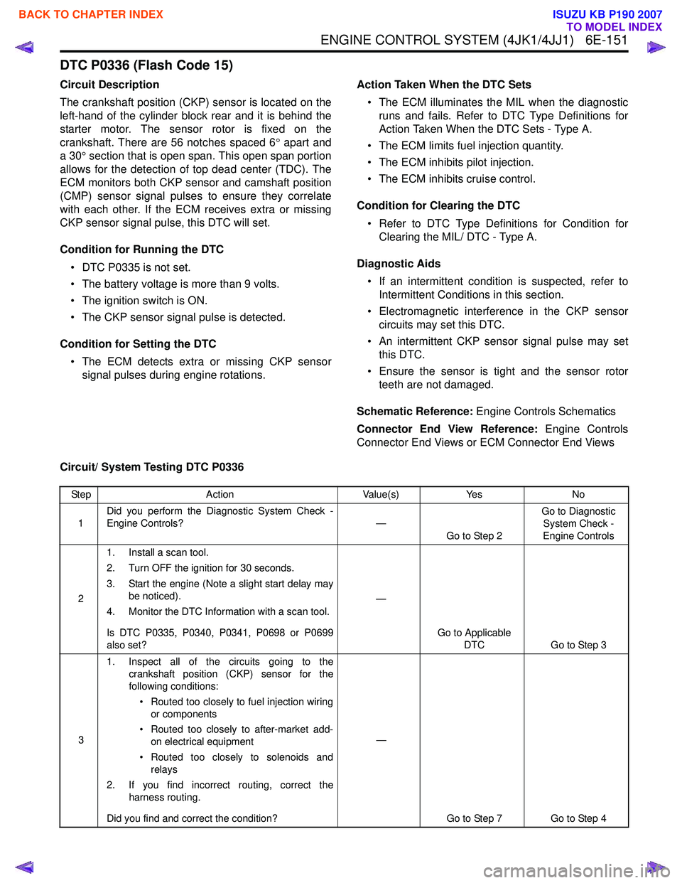
DTC P0336 (Flash Code 15)
Circuit Description
The crankshaft position (CKP) sensor is located on the
left-hand of the cylinder block rear and it is behind the
starter motor. The sensor rotor is fixed on the
crankshaft. There are 56 notches spaced 6 ° apart and
a 30 ° section that is open span. This open span portion
allows for the detection of top dead center (TDC). The
ECM monitors both CKP sensor and camshaft position
(CMP) sensor signal pulses to ensure they correlate
with each other. If the ECM receives extra or missing
CKP sensor signal pulse, this DTC will set.
Condition for Running the DTC • DTC P0335 is not set.
• The battery voltage is more than 9 volts.
• The ignition switch is ON.
• The CKP sensor signal pulse is detected.
Condition for Setting the DTC • The ECM detects extra or missing CKP sensor signal pulses during engine rotations. Action Taken When the DTC Sets
• The ECM illuminates the MIL when the diagnostic runs and fails. Refer to DTC Type Definitions for
Action Taken When the DTC Sets - Type A.
• The ECM limits fuel injection quantity.
• The ECM inhibits pilot injection.
• The ECM inhibits cruise control.
Condition for Clearing the DTC • Refer to DTC Type Definitions for Condition for Clearing the MIL/ DTC - Type A.
Diagnostic Aids • If an intermittent condition is suspected, refer to Intermittent Conditions in this section.
• Electromagnetic interference in the CKP sensor circuits may set this DTC.
• An intermittent CKP sensor signal pulse may set this DTC.
• Ensure the sensor is tight and the sensor rotor teeth are not damaged.
Schematic Reference: Engine Controls Schematics
Connector End View Reference: Engine Controls
Connector End Views or ECM Connector End Views
Circuit/ System Testing DTC P0336
Step Action Value(s)Yes No
1 Did you perform the Diagnostic System Check -
Engine Controls? —
Go to Step 2 Go to Diagnostic
System Check -
Engine Controls
2 1. Install a scan tool.
2. Turn OFF the ignition for 30 seconds.
3. Start the engine (Note a slight start delay may be noticed).
4. Monitor the DTC Information with a scan tool.
Is DTC P0335, P0340, P0341, P0698 or P0699
also set? —
Go to Applicable DTC Go to Step 3
3 1. Inspect all of the circuits going to the
crankshaft position (CKP) sensor for the
following conditions:
• Routed too closely to fuel injection wiring or components
• Routed too closely to after-market add- on electrical equipment
• Routed too closely to solenoids and relays
2. If you find incorrect routing, correct the harness routing.
Did you find and correct the condition? —
Go to Step 7 Go to Step 4
BACK TO CHAPTER INDEX
TO MODEL INDEX
ISUZU KB P190 2007
Page 1773 of 6020
6E-156 ENGINE CONTROL SYSTEM (4JK1/4JJ1)
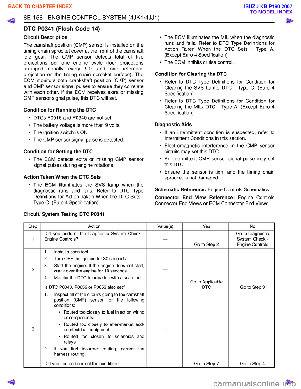
DTC P0341 (Flash Code 14)
Circuit Description
The camshaft position (CMP) sensor is installed on the
timing chain sprocket cover at the front of the camshaft
idle gear. The CMP sensor detects total of five
projections per one engine cycle (four projections
arranged equally every 90 ° and one reference
projection on the timing chain sprocket surface). The
ECM monitors both crankshaft position (CKP) sensor
and CMP sensor signal pulses to ensure they correlate
with each other. If the ECM receives extra or missing
CMP sensor signal pulse, this DTC will set.
Condition for Running the DTC • DTCs P0016 and P0340 are not set.
• The battery voltage is more than 9 volts.
• The ignition switch is ON.
• The CMP sensor signal pulse is detected.
Condition for Setting the DTC • The ECM detects extra or missing CMP sensor signal pulses during engine rotations.
Action Taken When the DTC Sets • The ECM illuminates the SVS lamp when the diagnostic runs and fails. Refer to DTC Type
Definitions for Action Taken When the DTC Sets -
Type C. (Euro 4 Specification) • The ECM illuminates the MIL when the diagnostic
runs and fails. Refer to DTC Type Definitions for
Action Taken When the DTC Sets - Type A.
(Except Euro 4 Specification)
• The ECM inhibits cruise control.
Condition for Clearing the DTC • Refer to DTC Type Definitions for Condition for Clearing the SVS Lamp/ DTC - Type C. (Euro 4
Specification)
• Refer to DTC Type Definitions for Condition for Clearing the MIL/ DTC - Type A. (Except Euro 4
Specification)
Diagnostic Aids • If an intermittent condition is suspected, refer to Intermittent Conditions in this section.
• Electromagnetic interference in the CMP sensor circuits may set this DTC.
• An intermittent CMP sensor signal pulse may set this DTC.
• Ensure the sensor is tight and the timing chain sprocket is not damaged.
Schematic Reference: Engine Controls Schematics
Connector End View Reference: Engine Controls
Connector End Views or ECM Connector End Views
Circuit/ System Testing DTC P0341
Step Action Value(s)Yes No
1 Did you perform the Diagnostic System Check -
Engine Controls? —
Go to Step 2 Go to Diagnostic
System Check -
Engine Controls
2 1. Install a scan tool.
2. Turn OFF the ignition for 30 seconds.
3. Start the engine. If the engine does not start, crank over the engine for 10 seconds.
4. Monitor the DTC Information with a scan tool.
Is DTC P0340, P0652 or P0653 also set? —
Go to Applicable DTC Go to Step 3
3 1. Inspect all of the circuits going to the camshaft
position (CMP) sensor for the following
conditions:
• Routed too closely to fuel injection wiring or components
• Routed too closely to after-market add- on electrical equipment
• Routed too closely to solenoids and relays
2. If you find incorrect routing, correct the harness routing.
Did you find and correct the condition? —
Go to Step 7 Go to Step 4
BACK TO CHAPTER INDEX
TO MODEL INDEX
ISUZU KB P190 2007
Page 1793 of 6020
6E-176 ENGINE CONTROL SYSTEM (4JK1/4JJ1)
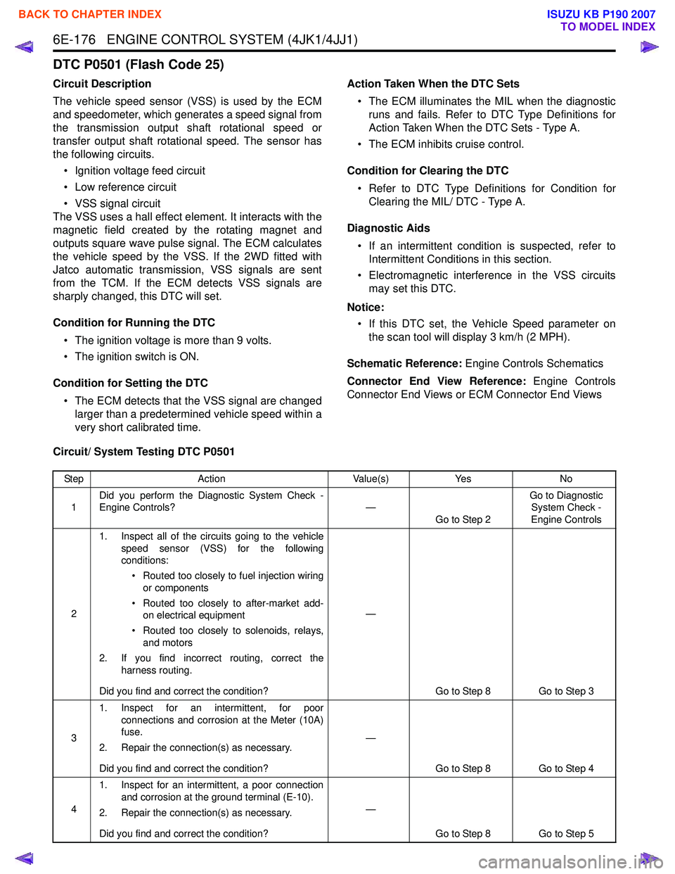
DTC P0501 (Flash Code 25)
Circuit Description
The vehicle speed sensor (VSS) is used by the ECM
and speedometer, which generates a speed signal from
the transmission output shaft rotational speed or
transfer output shaft rotational speed. The sensor has
the following circuits.
• Ignition voltage feed circuit
• Low reference circuit
• VSS signal circuit
The VSS uses a hall effect element. It interacts with the
magnetic field created by the rotating magnet and
outputs square wave pulse signal. The ECM calculates
the vehicle speed by the VSS. If the 2WD fitted with
Jatco automatic transmission, VSS signals are sent
from the TCM. If the ECM detects VSS signals are
sharply changed, this DTC will set.
Condition for Running the DTC • The ignition voltage is more than 9 volts.
• The ignition switch is ON.
Condition for Setting the DTC • The ECM detects that the VSS signal are changed larger than a predetermined vehicle speed within a
very short calibrated time. Action Taken When the DTC Sets
• The ECM illuminates the MIL when the diagnostic runs and fails. Refer to DTC Type Definitions for
Action Taken When the DTC Sets - Type A.
• The ECM inhibits cruise control.
Condition for Clearing the DTC • Refer to DTC Type Definitions for Condition for Clearing the MIL/ DTC - Type A.
Diagnostic Aids • If an intermittent condition is suspected, refer to Intermittent Conditions in this section.
• Electromagnetic interference in the VSS circuits may set this DTC.
Notice: • If this DTC set, the Vehicle Speed parameter on the scan tool will display 3 km/h (2 MPH).
Schematic Reference: Engine Controls Schematics
Connector End View Reference: Engine Controls
Connector End Views or ECM Connector End Views
Circuit/ System Testing DTC P0501
Step Action Value(s)Yes No
1 Did you perform the Diagnostic System Check -
Engine Controls? —
Go to Step 2 Go to Diagnostic
System Check -
Engine Controls
2 1. Inspect all of the circuits going to the vehicle
speed sensor (VSS) for the following
conditions:
• Routed too closely to fuel injection wiring or components
• Routed too closely to after-market add- on electrical equipment
• Routed too closely to solenoids, relays, and motors
2. If you find incorrect routing, correct the harness routing.
Did you find and correct the condition? —
Go to Step 8 Go to Step 3
3 1. Inspect for an intermittent, for poor
connections and corrosion at the Meter (10A)
fuse.
2. Repair the connection(s) as necessary.
Did you find and correct the condition? —
Go to Step 8 Go to Step 4
4 1. Inspect for an intermittent, a poor connection
and corrosion at the ground terminal (E-10).
2. Repair the connection(s) as necessary.
Did you find and correct the condition? —
Go to Step 8 Go to Step 5
BACK TO CHAPTER INDEX
TO MODEL INDEX
ISUZU KB P190 2007
Page 1940 of 6020
ENGINE CONTROL SYSTEM (4JK1/4JJ1) 6E-323
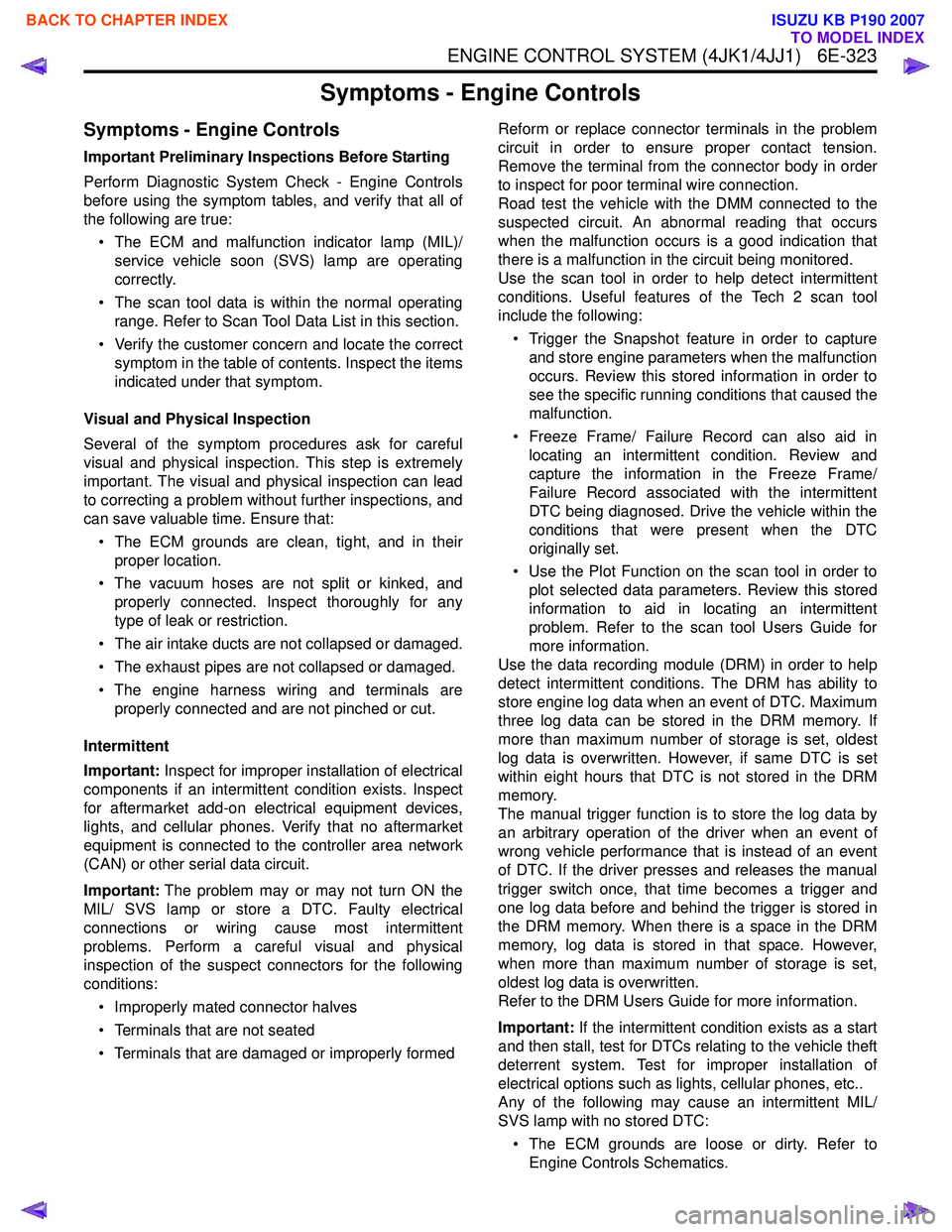
Symptoms - Engine Controls
Symptoms - Engine Controls
Important Preliminary Inspections Before Starting
Perform Diagnostic System Check - Engine Controls
before using the symptom tables, and verify that all of
the following are true:
• The ECM and malfunction indicator lamp (MIL)/ service vehicle soon (SVS) lamp are operating
correctly.
• The scan tool data is within the normal operating range. Refer to Scan Tool Data List in this section.
• Verify the customer concern and locate the correct symptom in the table of contents. Inspect the items
indicated under that symptom.
Visual and Physical Inspection
Several of the symptom procedures ask for careful
visual and physical inspection. This step is extremely
important. The visual and physical inspection can lead
to correcting a problem without further inspections, and
can save valuable time. Ensure that:
• The ECM grounds are clean, tight, and in their proper location.
• The vacuum hoses are not split or kinked, and properly connected. Inspect thoroughly for any
type of leak or restriction.
• The air intake ducts are not collapsed or damaged.
• The exhaust pipes are not collapsed or damaged.
• The engine harness wiring and terminals are properly connected and are not pinched or cut.
Intermittent
Important: Inspect for improper installation of electrical
components if an intermittent condition exists. Inspect
for aftermarket add-on electrical equipment devices,
lights, and cellular phones. Verify that no aftermarket
equipment is connected to the controller area network
(CAN) or other serial data circuit.
Important: The problem may or may not turn ON the
MIL/ SVS lamp or store a DTC. Faulty electrical
connections or wiring cause most intermittent
problems. Perform a careful visual and physical
inspection of the suspect connectors for the following
conditions:
• Improperly mated connector halves
• Terminals that are not seated
• Terminals that are damaged or improperly formed Reform or replace connector terminals in the problem
circuit in order to ensure proper contact tension.
Remove the terminal from the connector body in order
to inspect for poor terminal wire connection.
Road test the vehicle with the DMM connected to the
suspected circuit. An abnormal reading that occurs
when the malfunction occurs is a good indication that
there is a malfunction in the circuit being monitored.
Use the scan tool in order to help detect intermittent
conditions. Useful features of the Tech 2 scan tool
include the following:
• Trigger the Snapshot feature in order to capture and store engine parameters when the malfunction
occurs. Review this stored information in order to
see the specific running conditions that caused the
malfunction.
• Freeze Frame/ Failure Record can also aid in locating an intermittent condition. Review and
capture the information in the Freeze Frame/
Failure Record associated with the intermittent
DTC being diagnosed. Drive the vehicle within the
conditions that were present when the DTC
originally set.
• Use the Plot Function on the scan tool in order to plot selected data parameters. Review this stored
information to aid in locating an intermittent
problem. Refer to the scan tool Users Guide for
more information.
Use the data recording module (DRM) in order to help
detect intermittent conditions. The DRM has ability to
store engine log data when an event of DTC. Maximum
three log data can be stored in the DRM memory. If
more than maximum number of storage is set, oldest
log data is overwritten. However, if same DTC is set
within eight hours that DTC is not stored in the DRM
memory.
The manual trigger function is to store the log data by
an arbitrary operation of the driver when an event of
wrong vehicle performance that is instead of an event
of DTC. If the driver presses and releases the manual
trigger switch once, that time becomes a trigger and
one log data before and behind the trigger is stored in
the DRM memory. When there is a space in the DRM
memory, log data is stored in that space. However,
when more than maximum number of storage is set,
oldest log data is overwritten.
Refer to the DRM Users Guide for more information.
Important: If the intermittent condition exists as a start
and then stall, test for DTCs relating to the vehicle theft
deterrent system. Test for improper installation of
electrical options such as lights, cellular phones, etc..
Any of the following may cause an intermittent MIL/
SVS lamp with no stored DTC:
• The ECM grounds are loose or dirty. Refer to Engine Controls Schematics.
BACK TO CHAPTER INDEX
TO MODEL INDEX
ISUZU KB P190 2007
Page 1942 of 6020
ENGINE CONTROL SYSTEM (4JK1/4JJ1) 6E-325
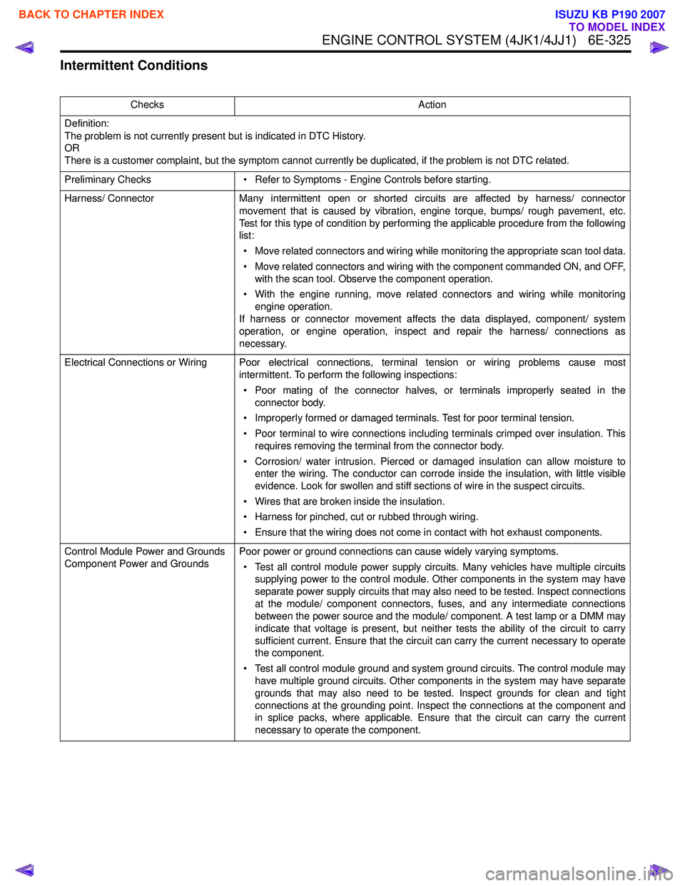
Intermittent Conditions
ChecksAction
Definition:
The problem is not currently present but is indicated in DTC History.
OR
There is a customer complaint, but the symptom cannot currently be duplicated, if the problem is not DTC related.
Preliminary Checks • Refer to Symptoms - Engine Controls before starting.
Harness/ Connector Many intermittent open or shorted circuits are affected by harness/ connector
movement that is caused by vibration, engine torque, bumps/ rough pavement, etc.
Test for this type of condition by performing the applicable procedure from the following
list:
• Move related connectors and wiring while monitoring the appropriate scan tool data.
• Move related connectors and wiring with the component commanded ON, and OFF, with the scan tool. Observe the component operation.
• With the engine running, move related connectors and wiring while monitoring engine operation.
If harness or connector movement affects the data displayed, component/ system
operation, or engine operation, inspect and repair the harness/ connections as
necessary.
Electrical Connections or Wiring Poor electrical connections, terminal tension or wiring problems cause most intermittent. To perform the following inspections:
• Poor mating of the connector halves, or terminals improperly seated in the connector body.
• Improperly formed or damaged terminals. Test for poor terminal tension.
• Poor terminal to wire connections including terminals crimped over insulation. This requires removing the terminal from the connector body.
• Corrosion/ water intrusion. Pierced or damaged insulation can allow moisture to enter the wiring. The conductor can corrode inside the insulation, with little visible
evidence. Look for swollen and stiff sections of wire in the suspect circuits.
• Wires that are broken inside the insulation.
• Harness for pinched, cut or rubbed through wiring.
• Ensure that the wiring does not come in contact with hot exhaust components.
Control Module Power and Grounds
Component Power and Grounds Poor power or ground connections can cause widely varying symptoms.
• Test all control module power supply circuits. Many vehicles have multiple circuits supplying power to the control module. Other components in the system may have
separate power supply circuits that may also need to be tested. Inspect connections
at the module/ component connectors, fuses, and any intermediate connections
between the power source and the module/ component. A test lamp or a DMM may
indicate that voltage is present, but neither tests the ability of the circuit to carry
sufficient current. Ensure that the circuit can carry the current necessary to operate
the component.
• Test all control module ground and system ground circuits. The control module may have multiple ground circuits. Other components in the system may have separate
grounds that may also need to be tested. Inspect grounds for clean and tight
connections at the grounding point. Inspect the connections at the component and
in splice packs, where applicable. Ensure that the circuit can carry the current
necessary to operate the component.
BACK TO CHAPTER INDEX
TO MODEL INDEX
ISUZU KB P190 2007
Page 1950 of 6020
ENGINE CONTROL SYSTEM (4JK1/4JJ1) 6E-333
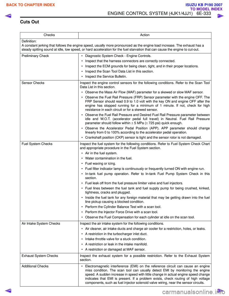
Cuts Out
ChecksAction
Definition:
A constant jerking that follows the engine speed, usually more pronounced as the engine load increase. The exhaust has a
steady spitting sound at idle, low speed, or hard acceleration for the fuel starvation that can cause the engine to cut-out.
Preliminary Check • Diagnostic System Check - Engine Controls.
• Inspect that the harness connectors are correctly connected.
• Inspect the ECM grounds for being clean, tight, and in their proper locations.
• Inspect the Scan Tool Data List in this section.
• Inspect the Service Bulletin.
Sensor Checks Inspect the engine control sensors for the following conditions. Refer to the Scan Tool
Data List in this section.
• Observe the Mass Air Flow (MAF) parameter for a skewed or slow MAF sensor.
• Observe the Fuel Rail Pressure (FRP) Sensor parameter with the engine OFF. The FRP Sensor should read 0.9 to 1.0 volt with the key ON and engine OFF after the
engine has stopped running for a minimum of 1 minute. If not, check for high
resistance in each circuit or for a skewed sensor.
• Observe the Fuel Rail Pressure and Desired Fuel Rail Pressure parameter between idle and W.O.T. (accelerator pedal full travel) in Neutral. Fuel Rail Pressure
parameter should follow within ± 5 MPa ( ± 725 psi) quick enough.
• Observe the Accelerator Pedal Position (APP). APP parameter should change linearly from 0 to 100% according to the accelerator pedal operation.
• Crankshaft position (CKP) sensor is tight and the sensor rotor is not damaged.
Fuel System Checks Inspect the fuel system for the following conditions. Refer to Fuel System Check Chart
and appropriate procedure in the Fuel System section.
• Air in the fuel system.
• Water contamination in the fuel.
• Fuel waxing or icing.
• Fuel filter indicator lamp is continuously or frequently turned ON with engine run.
• In-tank fuel pump operation. Refer to In-tank Fuel Pump System Check in this section.
• Fuel leak off from the fuel pressure limiter valve and fuel injectors.
• Fuel lines between the fuel tank and fuel supply pump for being crushed, kinked, tightness, cracks and plugged.
• Inside the fuel tank for any foreign material that may be getting drawn into the fuel line pickup causing a blocked condition.
• Perform the Cylinder Balance Test with a scan tool.
• Perform the Injector Force Drive with a scan tool.
• Observe the Fuel Compensation for each cylinder at idle on the scan tool.
Air Intake System Checks Inspect the air intake system for the following conditions.
• Air cleaner, air intake ducts and charge air cooler for a restriction, holes, or leaks.
• A restriction in the turbocharger inlet duct.
• Intake throttle valve for a stuck condition.
• A restriction or leak in the intake manifold.
• A restriction or damaged at MAF sensor.
Exhaust System Checks Inspect the exhaust system for a possible restriction. Refer to the Exhaust System
section.
Additional Checks • Electromagnetic interference (EMI) on the reference circuit can cause an engine
miss condition. The scan tool can usually detect EMI by monitoring the engine
speed. A sudden increase in speed with little change in actual engine speed change
indicates that EMI is present. If a problem exists, check routing of high voltage
components, such as fuel injector solenoid valve wiring, near the sensor circuits.
BACK TO CHAPTER INDEX
TO MODEL INDEX
ISUZU KB P190 2007
Page 2085 of 6020
ENGINE MECHANICAL (C24SE) 6A-71
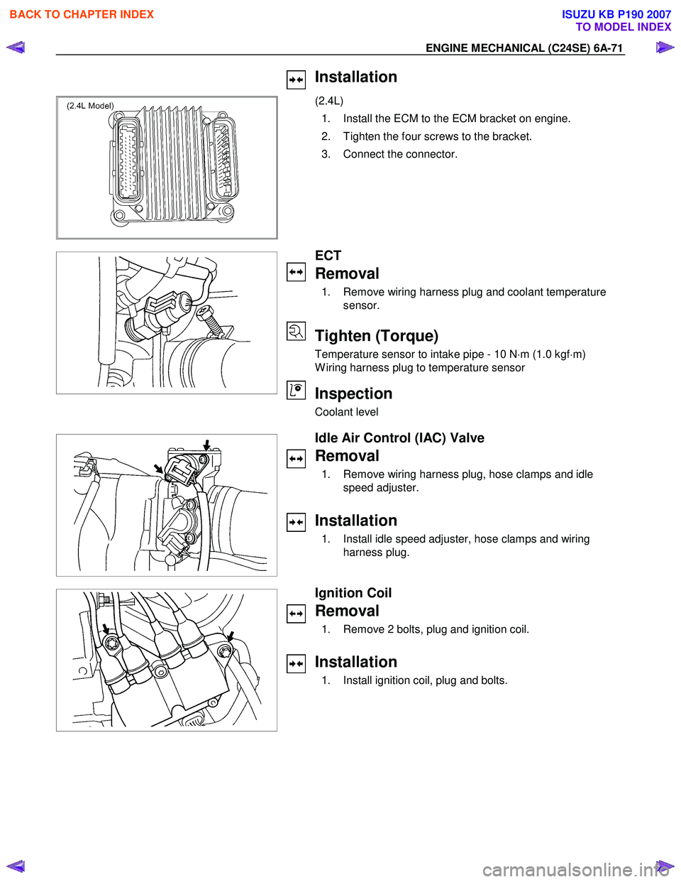
Installation
(2.4L)
1. Install the ECM to the ECM bracket on engine.
2. Tighten the four screws to the bracket.
3. Connect the connector.
ECT
Removal
1. Remove wiring harness plug and coolant temperature sensor.
Tighten (Torque)
Temperature sensor to intake pipe - 10 N ⋅m (1.0 kgf ⋅m)
W iring harness plug to temperature sensor
Inspection
Coolant level
Idle Air Control (IAC) Valve
Removal
1. Remove wiring harness plug, hose clamps and idle speed adjuster.
Installation
1. Install idle speed adjuster, hose clamps and wiring harness plug.
Ignition Coil
Removal
1. Remove 2 bolts, plug and ignition coil.
Installation
1. Install ignition coil, plug and bolts.
BACK TO CHAPTER INDEX
TO MODEL INDEX
ISUZU KB P190 2007
Page 2088 of 6020
6A-74 ENGINE MECHANICAL (C24SE)
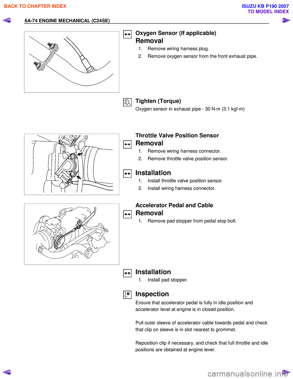
Oxygen Sensor (If applicable)
Removal
1. Remove wiring harness plug.
2. Remove oxygen sensor from the front exhaust pipe.
Tighten (Torque)
Oxygen sensor in exhaust pipe - 30 N ⋅m (3.1 kgf ⋅m)
Throttle Valve Position Sensor
Removal
1. Remove wiring harness connector.
2. Remove throttle valve position sensor.
Installation
1. Install throttle valve position sensor.
2. Install wiring harness connector.
Accelerator Pedal and Cable
Removal
1. Remove pad stopper from pedal stop bolt.
Installation
1. Install pad stopper.
Inspection
Ensure that accelerator pedal is fully in idle position and
accelerator level at engine is in closed position.
Pull outer sleeve of accelerator cable towards pedal and check
that clip on sleeve is in slot nearest to grommet.
Reposition clip if necessary, and check that full throttle and idle
positions are obtained at engine lever.
BACK TO CHAPTER INDEX
TO MODEL INDEX
ISUZU KB P190 2007