2007 ISUZU KB P190 CIRCUIT IMMOBILISER
[x] Cancel search: CIRCUIT IMMOBILISERPage 3499 of 6020
Engine Management – V6 – Diagnostics Page 6C1-2–221
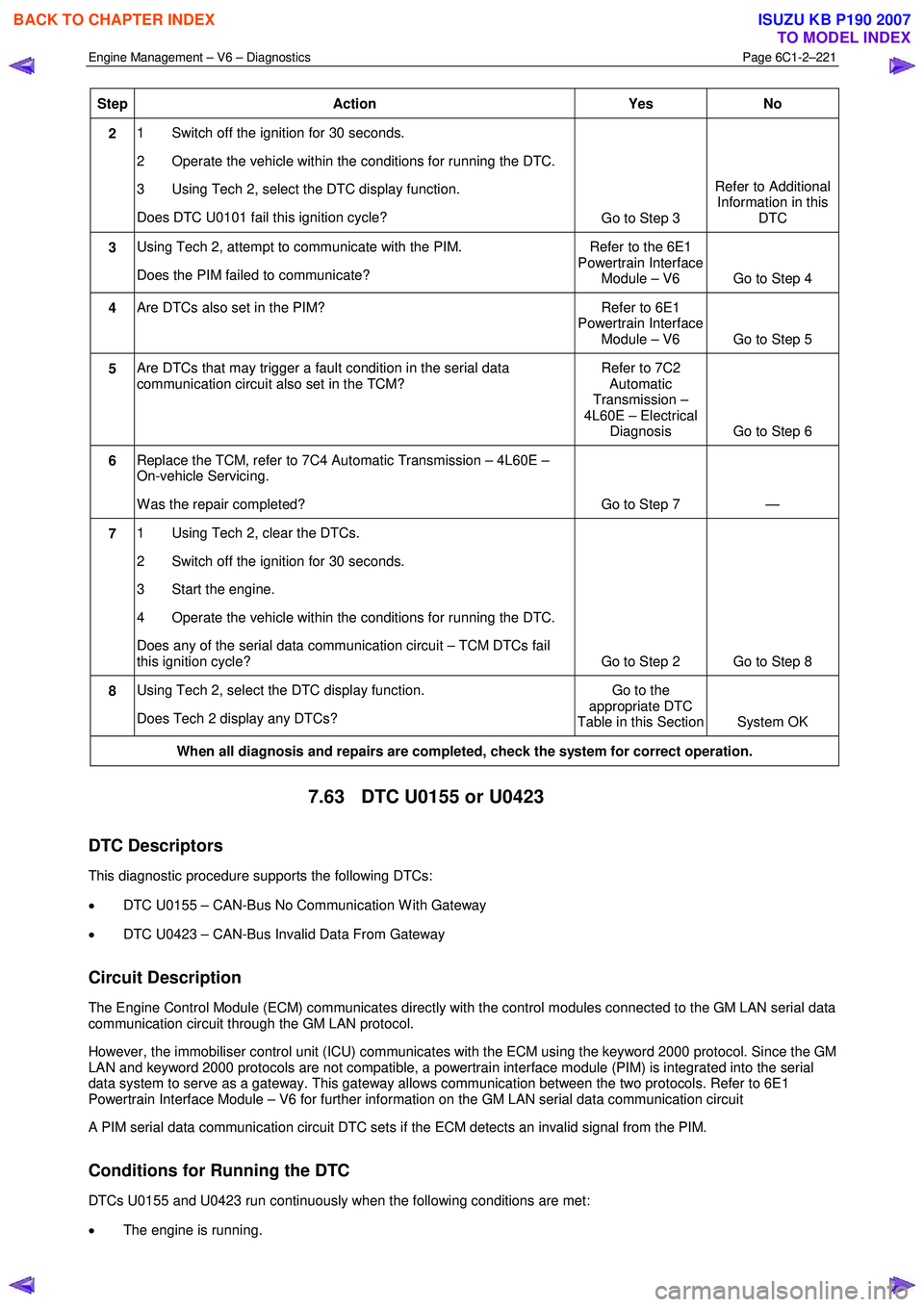
Step Action Yes No
2 1 Switch off the ignition for 30 seconds.
2 Operate the vehicle within the conditions for running the DTC.
3 Using Tech 2, select the DTC display function.
Does DTC U0101 fail this ignition cycle? Go to Step 3 Refer to Additional
Information in this DTC
3 Using Tech 2, attempt to communicate with the PIM.
Does the PIM failed to communicate? Refer to the 6E1
Powertrain Interface Module – V6 Go to Step 4
4 Are DTCs also set in the PIM? Refer to 6E1
Powertrain Interface Module – V6 Go to Step 5
5 Are DTCs that may trigger a fault condition in the serial data
communication circuit also set in the TCM? Refer to 7C2
Automatic
Transmission –
4L60E – Electrical Diagnosis Go to Step 6
6 Replace the TCM, refer to 7C4 Automatic Transmission – 4L60E –
On-vehicle Servicing.
W as the repair completed? Go to Step 7 —
7 1 Using Tech 2, clear the DTCs.
2 Switch off the ignition for 30 seconds.
3 Start the engine.
4 Operate the vehicle within the conditions for running the DTC.
Does any of the serial data communication circuit – TCM DTCs fail
this ignition cycle? Go to Step 2 Go to Step 8
8 Using Tech 2, select the DTC display function.
Does Tech 2 display any DTCs? Go to the
appropriate DTC
Table in this Section System OK
When all diagnosis and repairs are completed, check the system for correct operation.
7.63 DTC U0155 or U0423
DTC Descriptors
This diagnostic procedure supports the following DTCs:
• DTC U0155 – CAN-Bus No Communication W ith Gateway
• DTC U0423 – CAN-Bus Invalid Data From Gateway
Circuit Description
The Engine Control Module (ECM) communicates directly with the control modules connected to the GM LAN serial data
communication circuit through the GM LAN protocol.
However, the immobiliser control unit (ICU) communicates with the ECM using the keyword 2000 protocol. Since the GM
LAN and keyword 2000 protocols are not compatible, a powertrain interface module (PIM) is integrated into the serial
data system to serve as a gateway. This gateway allows communication between the two protocols. Refer to 6E1
Powertrain Interface Module – V6 for further information on the GM LAN serial data communication circuit
A PIM serial data communication circuit DTC sets if the ECM detects an invalid signal from the PIM.
Conditions for Running the DTC
DTCs U0155 and U0423 run continuously when the following conditions are met:
• The engine is running.
BACK TO CHAPTER INDEX
TO MODEL INDEX
ISUZU KB P190 2007
Page 3500 of 6020
Engine Management – V6 – Diagnostics Page 6C1-2–222
• The ignition voltage is 10.0 – 16.0 V.
Conditions for Setting the DTC
The ECM did not receive a valid signal from the PIM within the specified time frame.
Conditions for Clearing the DTC
The PIM serial data communication circuit DTCs are Type C DTCs. Refer to 1.4 Diagnostic Trouble Codes in this
Section, for action taken when a Type C DTC sets and conditions for clearing Type C DTCs.
Additional Information
• Refer to 6C1-1 Engine Management – V6 – General Information for details of the ECM operation.
• Since fault condition in a wiring connector may trigger DTCs, always test the connectors related to this diagnostic
procedure for shorted terminals or poor wiring connection before replacing any component. Refer to 8A Electrical -
Body and Chassis for information on electrical fault diagnosis.
• For an intermittent fault condition, refer to 5.2 Intermittent Fault Conditions in this Section.
• To assist diagnosis, refer to 3 W iring Diagrams and Connector Charts in this Section, for the system wiring
diagram and connector charts.
Test Description
The following number refers to the step numbers in the diagnostic table:
1 The following tests are included in the Diagnostic System Check.
• Tests the integrity of the GM LAN serial data communication circuit.
• Tests for fault conditions on the vehicle immobiliser system stored in the ICU.
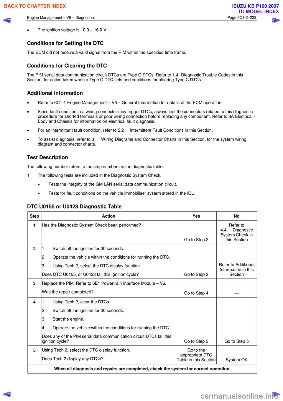
DTC U0155 or U0423 Diagnostic Table
Step Action Yes No
1 Has the Diagnostic System Check been performed?
Go to Step 2 Refer to
4.4 Diagnostic
System Check in this Section
2 1 Switch off the ignition for 30 seconds.
2 Operate the vehicle within the conditions for running the DTC.
3 Using Tech 2, select the DTC display function.
Does DTC U0155, or U0423 fail this ignition cycle? Go to Step 3 Refer to Additional
Information in this Section
3 Replace the PIM. Refer to 6E1 Powertrain Interface Module – V6.
W as the repair completed? Go to Step 4 —
4 1 Using Tech 2, clear the DTCs.
2 Switch off the ignition for 30 seconds.
3 Start the engine.
4 Operate the vehicle within the conditions for running the DTC.
Does any of the PIM serial data communication circuit DTCs fail this
ignition cycle? Go to Step 2 Go to Step 5
5 Using Tech 2, select the DTC display function.
Does Tech 2 display any DTCs? Go to the
appropriate DTC
Table in this Section System OK
When all diagnosis and repairs are completed, check the system for correct operation.
BACK TO CHAPTER INDEX
TO MODEL INDEX
ISUZU KB P190 2007
Page 3618 of 6020
Starting System – V6 Page 6D1-2–10
2.5 Starting System Inoperative /
Malfunctioning
Circuit Description
The battery cable supplies a constant connection from the battery to starter solenoid connector P – 4.
W hen the ignition switch is turned to the START position, 12 V is applied to the ECM connector C – 56 pin 31.
For vehicles with 4 speed automatic transmission, when the transmission is in park (P) or neutral (N), the park / neutral
and back-up switch grounds ECM connector C – 56 pin 32.
The ECM provides a ground for the start relay, ECM connector C – 56 pin 35 to start relay connector X – 13 pin 5.
W hen activated the start relay provides 12 V to starter solenoid connector P – 3 pin 1.
The solenoid closes its switch contacts to connect the battery voltage at the solenoid switch terminal P – 4 terminal B to
the DC motor. The pull-in winding of the solenoid switch is grounded through the DC motor winding and brushes. The
hold-in winding is grounded through the solenoid casing. The DC motor is grounded through the starter motor casing.
Refer to 2.4 W iring Diagram to aid in diagnosis.
Diagnostic Table Notes
Reference to following information will assist when diagnosing starting circuit faults:
1 If the battery, starter motor and fuel system are deemed as serviceable and a ‘no crank’ and / or ‘no start’ condition exists, refer to the following Sections as required:
a 11A Immobiliser for theft deterrent engine crank inhibitor related faults
b 6C1-2 Engine Management V6 Diagnostics, for starter relay circuit faults
2 For all wiring harness fault diagnoses, refer to 8A Electrical Body and Chassis.
3 For wiring harness repairs, refer to 8A Electrical Body and Chassis.
4 Refer to 8A Electrical Body and Chassis for harness routing.
5 Ensure the battery, cables and connections are in good order. Refer to 8A Electrical Body and Chassis.
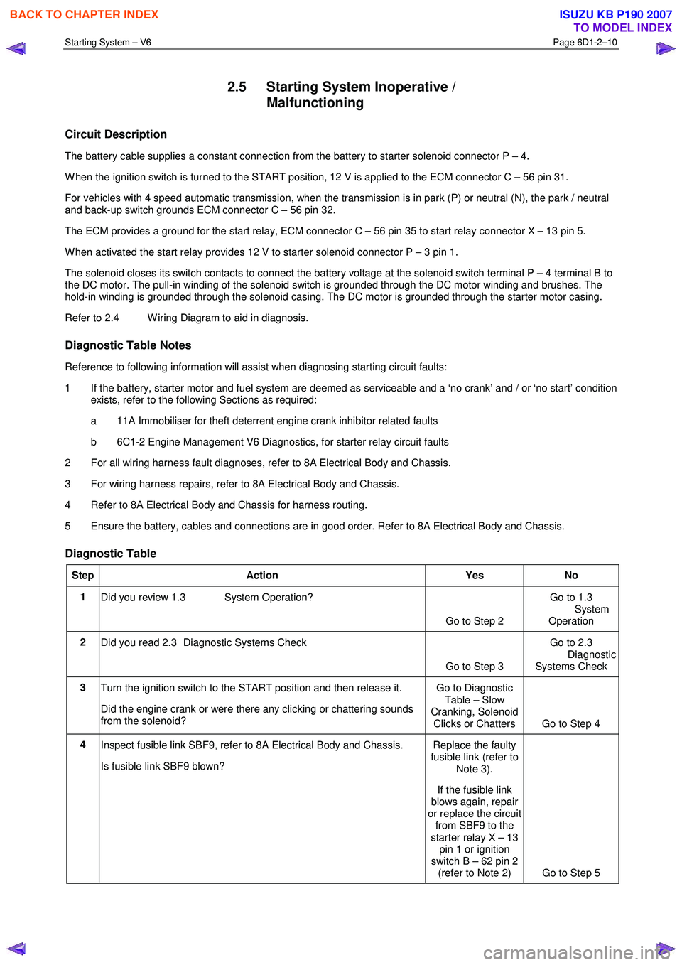
Diagnostic Table
Step Action Yes No
1
Did you review 1.3 System Operation?
Go to Step 2 Go to 1.3
System
Operation
2 Did you read 2.3 Diagnostic Systems Check
Go to Step 3 Go to 2.3
Diagnostic Systems Check
3 Turn the ignition switch to the START position and then release it.
Did the engine crank or were there any clicking or chattering sounds
from the solenoid? Go to Diagnostic
Table – Slow
Cranking, Solenoid Clicks or Chatters Go to Step 4
4 Inspect fusible link SBF9, refer to 8A Electrical Body and Chassis.
Is fusible link SBF9 blown? Replace the faulty
fusible link (refer to
Note 3).
If the fusible link
blows again, repair
or replace the circuit from SBF9 to the
starter relay X – 13 pin 1 or ignition
switch B – 62 pin 2 (refer to Note 2) Go to Step 5
BACK TO CHAPTER INDEX
TO MODEL INDEX
ISUZU KB P190 2007
Page 3662 of 6020
Powertrain Interface Module – V6 Page 6E1–1
6E1
Powertrain Interface Module – V6
ATTENTION
Before performing any service operation or other procedure described in this Section, refer to 1.2 Warning
Caution and Notes for correct workshop practices with regard to safety and / or property damage.
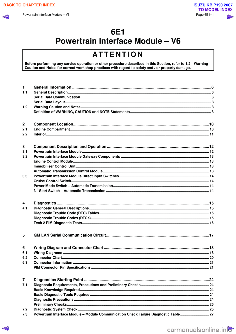
1 General Information ............................................................................................................ ...................6
1.1 General Description ............................................................................................................ ................................... 6
Serial Data Communication .................................................................................................................................. 6
Serial Data Layout.................................................................................................................................................. 8
1.2 Warning Caution and Notes .................................................................................................................................. 8
Definition of WARNING, CAUTION and NOTE Statements ............................................................................. .... 8
2 Component Location............................................................................................................................10
2.1 Engine Compartment............................................................................................................. .............................. 10
2.2 Interior................................................................................................................................................................... 11
3 Component Description and Operation ............................................................................................ .12
3.1 Powertrain Interface Module ............................................................................................................................... 12
3.2 Powertrain Interface Module Gateway Components ................................................................................. ....... 13
Engine Control Module........................................................................................................................................ 13
Immobiliser Control Unit ..................................................................................................................................... 13
Automatic Transmission Control Module .......................................................................................... ................ 13
3.3 Powertrain Interface Module Direct Input Switches.............................................................................. ............ 14
Cruise Control Switch.......................................................................................................................................... 14
Power Mode Switch – Automatic Transmission..................................................................................... ........... 14
3rd Start Switch – Automatic Transmission ....................................................................................................... 14
4 Diagnostics ...........................................................................................................................................15
4.1 Diagnostic General Descriptions................................................................................................ ........................ 15
Diagnostic Trouble Code (DTC) Tables........................................................................................... ................... 15
Diagnostic Trouble Codes (DTCs) ...................................................................................................................... 15
Tech 2 PIM Diagnostic Tests............................................................................................................................... 16
5 GM LAN Serial Communication Circuit ............................................................................................ ..17
6 Wiring Diagram and Connector Chart ................................................................................................18
6.1 Wiring Diagrams .................................................................................................................................................. 18
6.2 Connector Chart................................................................................................................................................... 20
6.3 Connector Information .......................................................................................................... .............................. 21
PIM Connector Pin Specifications ............................................................................................... ....................... 21
7 Diagnostics Starting Point ..................................................................................................................24
7.1 Diagnostic Requirements, Precautions and Preliminary Checks .................................................................... 24
Basic Knowledge Required ................................................................................................................................. 24
Basic Diagnostic Tools Required ................................................................................................ ....................... 24
Diagnostic Precautions ....................................................................................................................................... 24
Preliminary Checks.............................................................................................................................................. 25
7.2 Diagnostic System Check ........................................................................................................ ........................... 25
7.3 Powertrain Interface Module – Module Communication Check Failure Diagnostic Table............................. 27
BACK TO CHAPTER INDEX
TO MODEL INDEX
ISUZU KB P190 2007
Page 3664 of 6020
Powertrain Interface Module – V6 Page 6E1–3
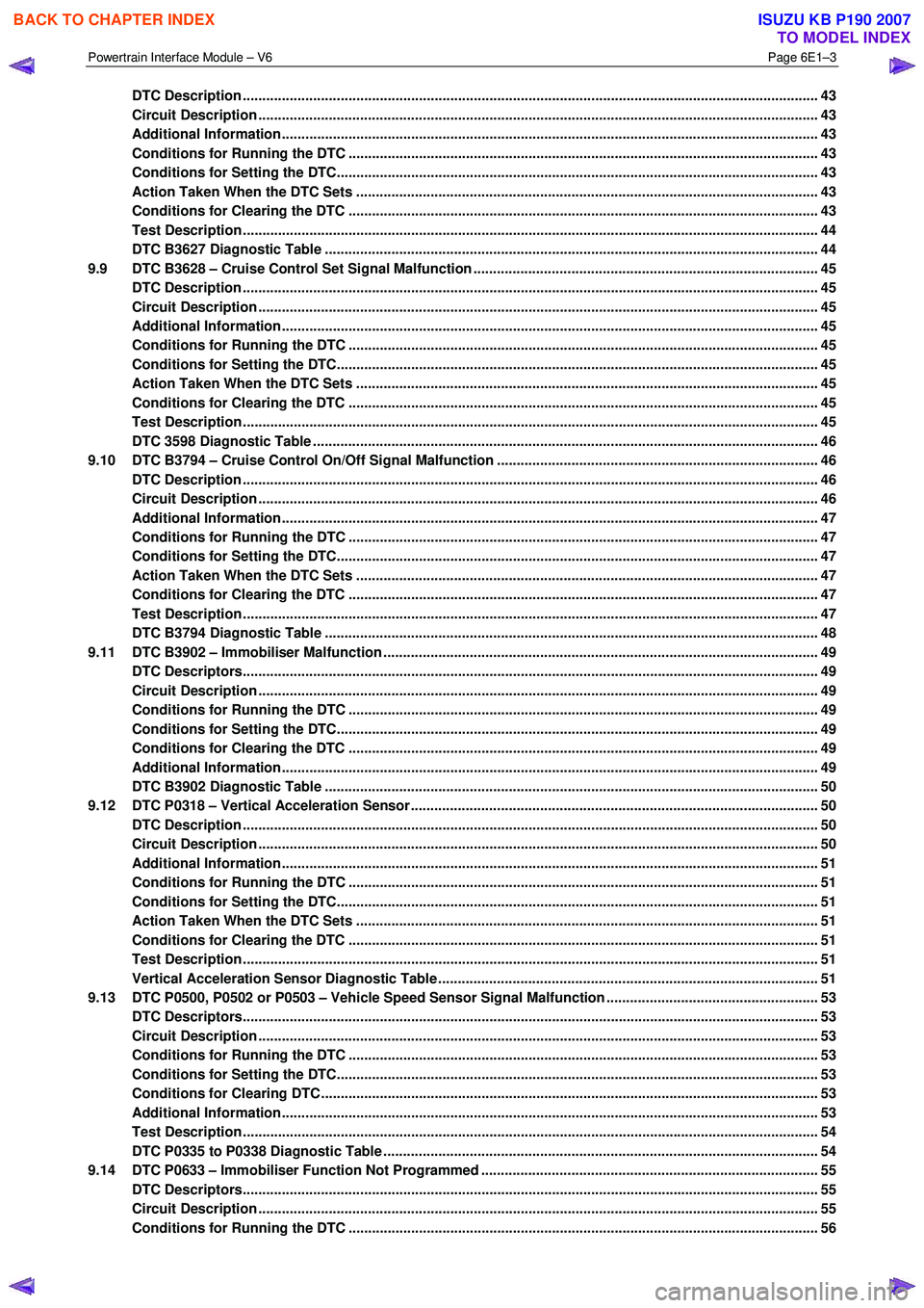
DTC Description ................................................................................................................................................... 43
Circuit Description ............................................................................................................................................... 43
Additional Information......................................................................................................... ................................ 43
Conditions for Running the DTC ................................................................................................. ....................... 43
Conditions for Setting the DTC........................................................................................................................... 43
Action Taken When the DTC Sets ................................................................................................. ..................... 43
Conditions for Clearing the DTC ........................................................................................................................ 43
Test Description ................................................................................................................................................... 44
DTC B3627 Diagnostic Table ..................................................................................................... ......................... 44
9.9 DTC B3628 – Cruise Control Set Signal Malfunction .............................................................................. .......... 45
DTC Description ................................................................................................................................................... 45
Circuit Description ............................................................................................................................................... 45
Additional Information......................................................................................................... ................................ 45
Conditions for Running the DTC ................................................................................................. ....................... 45
Conditions for Setting the DTC........................................................................................................................... 45
Action Taken When the DTC Sets ................................................................................................. ..................... 45
Conditions for Clearing the DTC ........................................................................................................................ 45
Test Description ................................................................................................................................................... 45
DTC 3598 Diagnostic Table ...................................................................................................... ........................... 46
9.10 DTC B3794 – Cruise Control On/Off Signal Malfunction ........................................................................... ....... 46
DTC Description ................................................................................................................................................... 46
Circuit Description ............................................................................................................................................... 46
Additional Information......................................................................................................... ................................ 47
Conditions for Running the DTC ................................................................................................. ....................... 47
Conditions for Setting the DTC........................................................................................................................... 47
Action Taken When the DTC Sets ................................................................................................. ..................... 47
Conditions for Clearing the DTC ........................................................................................................................ 47
Test Description ................................................................................................................................................... 47
DTC B3794 Diagnostic Table ..................................................................................................... ......................... 48
9.11 DTC B3902 – Immobiliser Malfunction ............................................................................................ ................... 49
DTC Descriptors................................................................................................................................................... 49
Circuit Description ............................................................................................................................................... 49
Conditions for Running the DTC ................................................................................................. ....................... 49
Conditions for Setting the DTC........................................................................................................................... 49
Conditions for Clearing the DTC ................................................................................................ ........................ 49
Additional Information......................................................................................................................................... 49
DTC B3902 Diagnostic Table ..................................................................................................... ......................... 50
9.12 DTC P0318 – Vertical Acceleration Sensor....................................................................................... ................. 50
DTC Description ................................................................................................................................................... 50
Circuit Description ............................................................................................................................................... 50
Additional Information......................................................................................................... ................................ 51
Conditions for Running the DTC ................................................................................................. ....................... 51
Conditions for Setting the DTC........................................................................................................................... 51
Action Taken When the DTC Sets ................................................................................................. ..................... 51
Conditions for Clearing the DTC ........................................................................................................................ 51
Test Description ................................................................................................................................................... 51
Vertical Acceleration Sensor Diagnostic Table .................................................................................. ............... 51
9.13 DTC P0500, P0502 or P0503 – Vehicle Speed Sensor Signal Malfunction ...................................................... 53
DTC Descriptors................................................................................................................................................... 53
Circuit Description ............................................................................................................................................... 53
Conditions for Running the DTC ................................................................................................. ....................... 53
Conditions for Setting the DTC........................................................................................................................... 53
Conditions for Clearing DTC ............................................................................................................................... 53
Additional Information......................................................................................................................................... 53
Test Description ................................................................................................................................................... 54
DTC P0335 to P0338 Diagnostic Table ............................................................................................ ................... 54
9.14 DTC P0633 – Immobiliser Function Not Programmed ................................................................................ ...... 55
DTC Descriptors................................................................................................................................................... 55
Circuit Description ............................................................................................................................................... 55
Conditions for Running the DTC ................................................................................................. ....................... 56
BACK TO CHAPTER INDEX
TO MODEL INDEX
ISUZU KB P190 2007
Page 3667 of 6020
Powertrain Interface Module – V6 Page 6E1–6
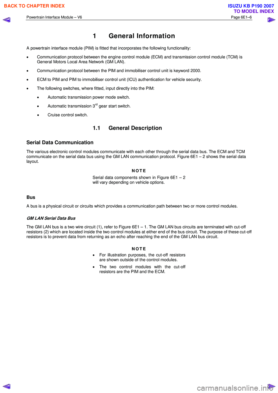
1 General Information
A powertrain interface module (PIM) is fitted that incorporates the following functionality:
• Communication protocol between the engine control module (ECM) and transmission control module (TCM) is
General Motors Local Area Network (GM LAN).
• Communication protocol between the PIM and immobiliser control unit is keyword 2000.
• ECM to PIM and PIM to immobiliser control unit (ICU) authentication for vehicle security.
• The following switches, where fitted, input directly into the PIM:
• Automatic transmission power mode switch.
• Automatic transmission 3
rd gear start switch.
• Cruise control switch.
1.1 General Description
Serial Data Communication
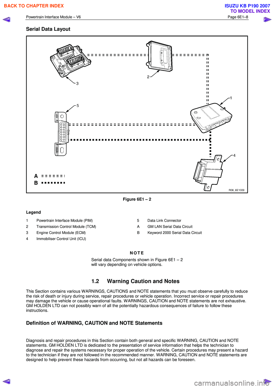
The various electronic control modules communicate with each other through the serial data bus. The ECM and TCM
communicate on the serial data bus using the GM LAN communication protocol. Figure 6E1 – 2 shows the serial data
layout.
NOTE
Serial data components shown in Figure 6E1 – 2
will vary depending on vehicle options.
Bus
A bus is a physical circuit or circuits which provides a communication path between two or more control modules.
GM LAN Serial Data Bus
The GM LAN bus is a two wire circuit (1), refer to Figure 6E1 – 1. The GM LAN bus circuits are terminated with cut-off
resistors (2) which are located inside the two control modules at either end of the bus circuit. The purpose of these cut-off
resistors is to prevent data from returning as an echo after reaching the end of the GM LAN bus circuit.
NOTE
• For illustration purposes, the cut-off resistors
are shown outside of the control modules.
• The two control modules with the cut-off
resistors are the PIM and the ECM.
BACK TO CHAPTER INDEX
TO MODEL INDEX
ISUZU KB P190 2007
Page 3669 of 6020
Powertrain Interface Module – V6 Page 6E1–8
Serial Data Layout
Figure 6E1 – 2
Legend
1 Powertrain Interface Module (PIM)
2 Transmission Control Module (TCM)
3 Engine Control Module (ECM)
4 Immobiliser Control Unit (ICU)
5 Data Link Connector
A GM LAN Serial Data Circuit
B Keyword 2000 Serial Data Circuit
NOTE
Serial data Components shown in Figure 6E1 – 2
will vary depending on vehicle options.
1.2 Warning Caution and Notes
This Section contains various W ARNINGS, CAUTIONS and NOTE statements that you must observe carefully to reduce
the risk of death or injury during service, repair procedures or vehicle operation. Incorrect service or repair procedures
may damage the vehicle or cause operational faults. W ARNINGS, CAUTION and NOTE statements are not exhaustive.
GM HOLDEN LTD can not possibly warn of all the potentially hazardous consequences of failure to follow these
instructions.
Definition of WARNING, CAUTION and NOTE Statements
Diagnosis and repair procedures in this Section contain both general and specific W ARNING, CAUTION and NOTE
statements. GM HOLDEN LTD is dedicated to the presentation of service information that helps the technician to
diagnose and repair the systems necessary for proper operation of the vehicle. Certain procedures may present a hazard
to the technician if they are not followed in the recommended manner. W ARNING, CAUTION and NOTE statements are
designed to help prevent these hazards from occurring, but not all hazards can be foreseen.
BACK TO CHAPTER INDEX
TO MODEL INDEX
ISUZU KB P190 2007
Page 3682 of 6020
Powertrain Interface Module – V6 Page 6E1–21
6.3 Connector Information
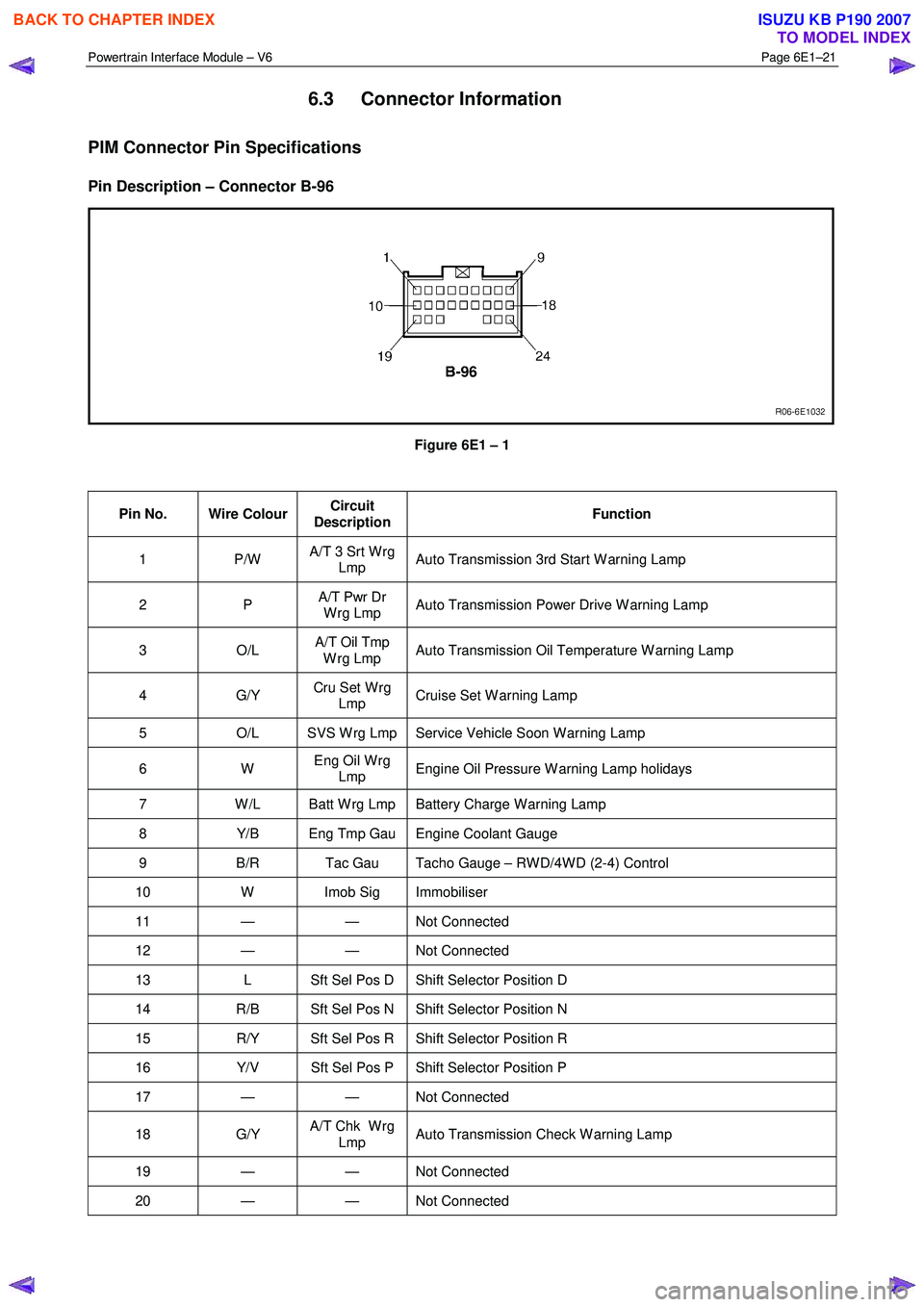
PIM Connector Pin Specifications
Pin Description – Connector B-96
Figure 6E1 – 1
Pin No. Wire Colour Circuit
Description Function
1 P/W
A/T 3 Srt W rg
Lmp Auto Transmission 3rd Start W arning Lamp
2 P
A/T Pwr Dr
W rg Lmp Auto Transmission Power Drive W arning Lamp
3 O/L A/T Oil Tmp
W rg Lmp Auto Transmission Oil Temperature W arning Lamp
4 G/Y
Cru Set W rg
Lmp Cruise Set W arning Lamp
5
O/L SVS W rg Lmp Service Vehicle Soon W arning Lamp
6 W Eng Oil W rg
Lmp Engine Oil Pressure W arning Lamp holidays
7
W /L Batt W rg Lmp Battery Charge W arning Lamp
8 Y/B Eng Tmp Gau Engine Coolant Gauge
9 B/R Tac Gau Tacho Gauge – RW D/4W D (2-4) Control
10 W Imob Sig Immobiliser
11 — — Not Connected
12 — — Not Connected
13 L Sft Sel Pos D Shift Selector Position D
14 R/B Sft Sel Pos N Shift Selector Position N
15 R/Y Sft Sel Pos R Shift Selector Position R
16 Y/V Sft Sel Pos P Shift Selector Position P
17 — — Not Connected
18 G/Y A/T Chk W rg
Lmp Auto Transmission Check W arning Lamp
19 — — Not
Connected
20 — — Not Connected
BACK TO CHAPTER INDEX
TO MODEL INDEX
ISUZU KB P190 2007