2007 ISUZU KB P190 check engine
[x] Cancel search: check enginePage 1349 of 6020
6F – 16 EXHAUST SYSTEM
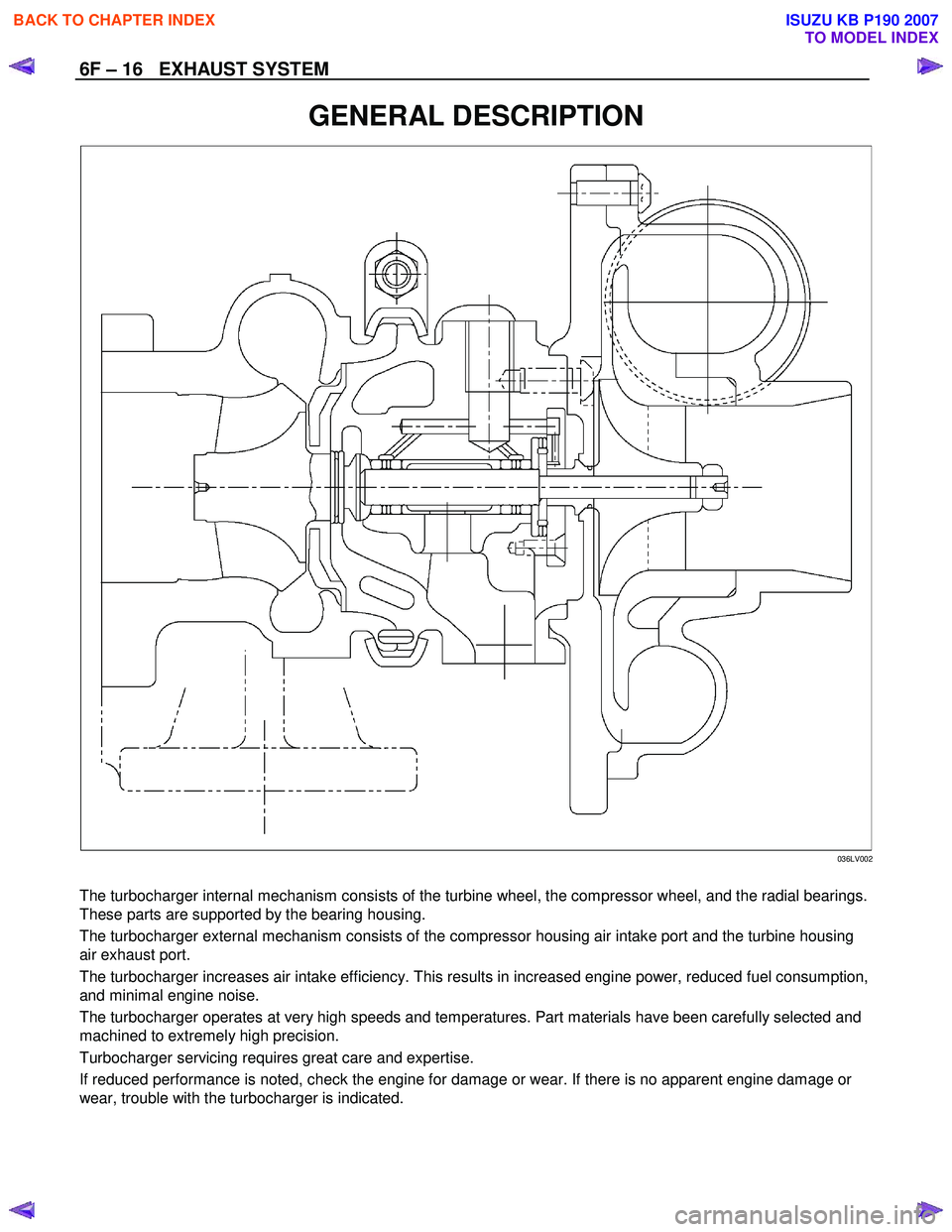
GENERAL DESCRIPTION
036LV002
The turbocharger internal mechanism consists of the turbine wheel, the compressor wheel, and the radial bearings.
These parts are supported by the bearing housing.
The turbocharger external mechanism consists of the compressor housing air intake port and the turbine housing
air exhaust port.
The turbocharger increases air intake efficiency. This results in increased engine power, reduced fuel consumption,
and minimal engine noise.
The turbocharger operates at very high speeds and temperatures. Part materials have been carefully selected and
machined to extremely high precision.
Turbocharger servicing requires great care and expertise.
If reduced performance is noted, check the engine for damage or wear. If there is no apparent engine damage or
wear, trouble with the turbocharger is indicated.
BACK TO CHAPTER INDEX
TO MODEL INDEX
ISUZU KB P190 2007
Page 1350 of 6020
EXHAUST SYSTEM 6F – 17
INSPECTION AND REPAIR
Make the necessary adjustments, repairs, and part replacements if excessive wear or damage is discovered during
inspection.
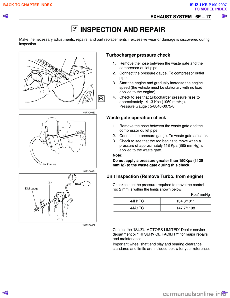
Turbocharger pressure check
1. Remove the hose between the waste gate and the
compressor outlet pipe.
2. Connect the pressure gauge. To compressor outlet pipe.
3. Start the engine and gradually increase the engine speed (the vehicle must be stationary with no load
applied to the engine).
4. Check to see that turbocharger pressure rises to approximately 141.3 Kpa (1060 mmHg).
Pressure Gauge : 5-8840-0075-0
150RY00030
Waste gate operation check
1. Remove the hose between the waste gate and the compressor outlet pipe.
2. Connect the pressure gauge. To waste gate actuator.
3. Check to see that the rod begins to move when a pressure of approximately 118 Kpa (885 mmHg) is
applied to the waste gate.
Note:
Do not apply a pressure greater than 150Kpa (1125
mmHg) to the waste gate during this check.
150RY00031
Unit Inspection (Remove Turbo. from engine)
Check to see the pressure required to move the control
rod 2 mm is within the limits shown below.
Kpa/mmHg
4JH1TC 134.8/1011
4JA1TC 147.7/1108
150RY00032
Contact the “ISUZU MOTORS LIMITED” Dealer service
department or “IHI SERVICE FACILITY” for major repairs
and maintenance.
Important wheel shaft end play and bearing clearance
standards and limits are included below for your reference.
BACK TO CHAPTER INDEX
TO MODEL INDEX
ISUZU KB P190 2007
Page 1359 of 6020
6H – 6 ACCELERATOR CONTROL
RTW 46HMH000201
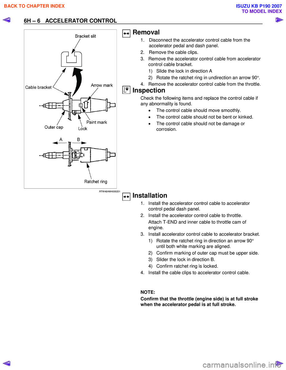
Removal
1. Disconnect the accelerator control cable from the
accelerator pedal and dash panel.
2. Remove the cable clips.
3. Remove the accelerator control cable from accelerator control cable bracket.
1) Slide the lock in direction A
2) Rotate the ratchet ring in undirection an arrow 90 °.
4. Remove the accelerator control cable from the throttle.
Inspection
Check the following items and replace the control cable if
any abnormality is found.
• The control cable should move smoothly.
• The control cable should not be bent or kinked.
• The control cable should not be damage or
corrosion.
Installation
1. Install the accelerator control cable to accelerator control pedal dash panel.
2. Install the accelerator control cable to throttle.
Attach T-END and inner cable to throttle cam of engine.
3. Install accelerator control cable to accelerator bracket.
1) Rotate the ratchet ring in direction an arrow 90 °
until both white marking are aligned.
2) Confirm marking of outer cap must be upper side.
3) Slider the lock in direction B.
4) Confirm ratchet ring is locked.
4. Install the cable clips to accelerator control cable.
NOTE:
Confirm that the throttle (engine side) is at full stroke
when the accelerator pedal is at full stroke.
BACK TO CHAPTER INDEX
TO MODEL INDEX
ISUZU KB P190 2007
Page 1362 of 6020
6A-2 ENGINE MECHANICAL (4JK1/4JJ1)
Special Tools ...................................................6A-110
Flywheel .............................................................6A-111 Components ....................................................6A-111
Removal ..........................................................6A-111
Inspection ........................................................6A-113
Installation .......................................................6A-113
Torque Specifications......................................6A-115
Special Tools ...................................................6A-115
Gear Case Assembly .........................................6A-116 Components ....................................................6A-116
Removal ..........................................................6A-117
Installation .......................................................6A-118
Torque Specifications......................................6A-119
Crankshaft Front Oil Seal ...................................6A-120 Components ....................................................6A-120
Removal ..........................................................6A-120
Installation .......................................................6A-121
Torque Specifications......................................6A-122
Special Tools ...................................................6A-122
Crankshaft Rear Oil Seal ...................................6A-123 Components ....................................................6A-123
Removal ..........................................................6A-124
Installation .......................................................6A-124
Special Tools ...................................................6A-125
Crankshaft ..........................................................6A-126 Components ....................................................6A-126
Removal ..........................................................6A-127
Disassembly ....................................................6A-127
Reassembly.....................................................6A-128
Inspection ........................................................6A-128
Installation .......................................................6A-132
Torque Specifications......................................6A-135
Cylinder Block ....................................................6A-136 Components ....................................................6A-136
Removal ..........................................................6A-136
Inspection ........................................................6A-137
Installation .......................................................6A-139
Lubrication System .............................................6A-140 Service Precautions ........................................6A-140
Functional Check ............................................6A-141
Oil Filter Cartridge ..............................................6A-143 Components ....................................................6A-143
Removal ..........................................................6A-143
Installation .......................................................6A-143
Special Tools ...................................................6A-144
Oil Filter Assembly and Oil Cooler .....................6A-145 Components ....................................................6A-145
Removal ..........................................................6A-145
Disassembly ....................................................6A-146
Reassembly.....................................................6A-147 Installation ....................................................... 6A-147
Crank Case and Oil Pan .................................... 6A-150 Components .................................................... 6A-150
Removal .......................................................... 6A-151
Disassembly .................................................... 6A-152
Reassembly .................................................... 6A-152
Installation ....................................................... 6A-153
Torque Specifications...................................... 6A-155
Oil Pump ............................................................ 6A-156 Components .................................................... 6A-156
Removal .......................................................... 6A-156
Disassembly .................................................... 6A-157
Reassembly .................................................... 6A-158
Inspection ........................................................ 6A-158
Installation ....................................................... 6A-159
Oil Pressure SW ................................................ 6A-161 Components .................................................... 6A-161
Removal .......................................................... 6A-162
Inspection ........................................................ 6A-162
Installation ....................................................... 6A-162
Circuit check.................................................... 6A-162
Air Cleaner Element ........................................... 6A-163 Removal .......................................................... 6A-163
Cleaning .......................................................... 6A-163
Installation ....................................................... 6A-163
BACK TO CHAPTER INDEX
TO MODEL INDEX
ISUZU KB P190 2007
Page 1381 of 6020
ENGINE MECHANICAL (4JK1/4JJ1) 6A-21
Removal
1. Remove the engine hood.
2. Remove the engine cover.
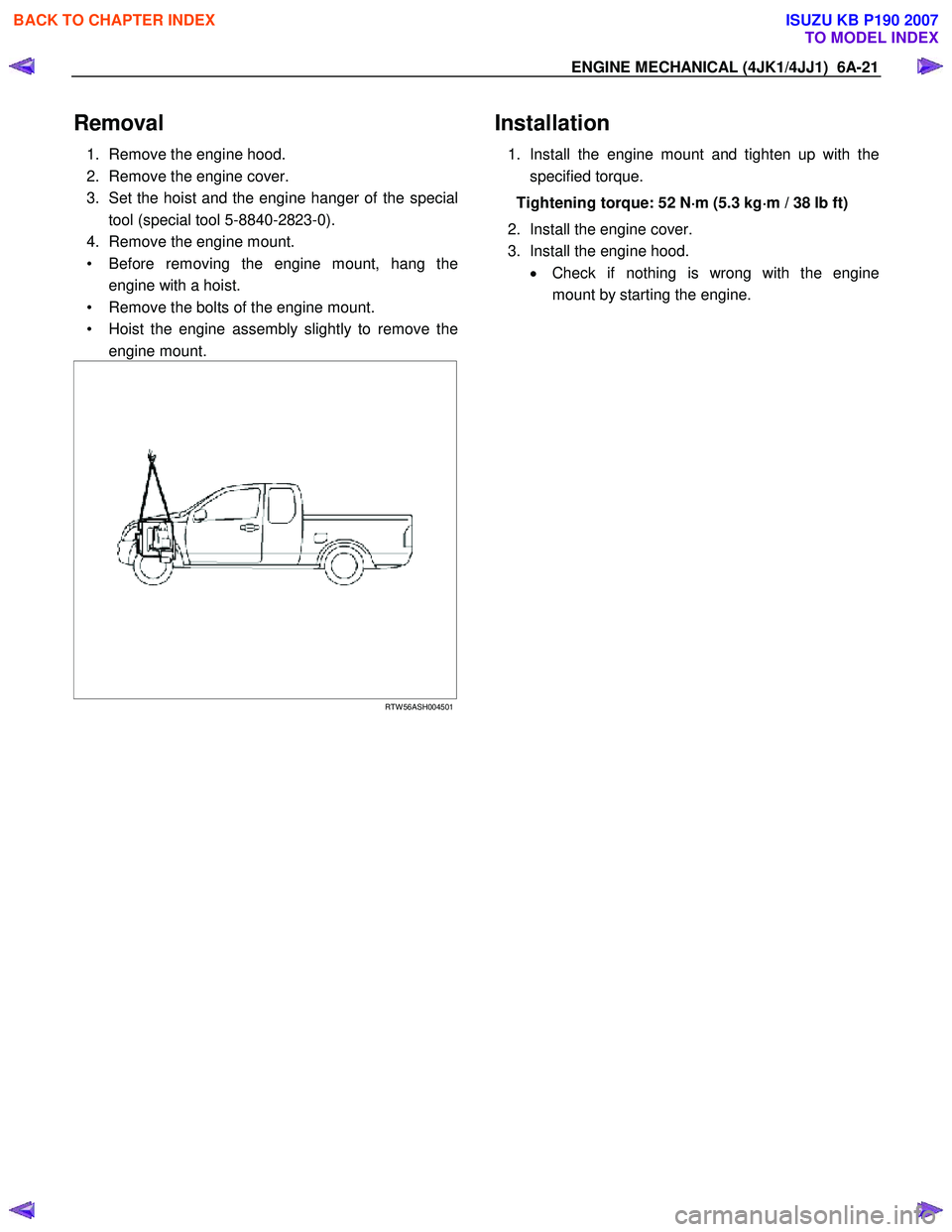
3. Set the hoist and the engine hanger of the special tool (special tool 5-8840-2823-0).
4. Remove the engine mount.
• Before removing the engine mount, hang the engine with a hoist.
• Remove the bolts of the engine mount.
• Hoist the engine assembly slightly to remove the engine mount.
RTW 56ASH004501
Installation
1. Install the engine mount and tighten up with the
specified torque.
Tightening torque: 52 N ⋅
⋅⋅
⋅
m (5.3 kg ⋅
⋅⋅
⋅
m / 38 lb ft)
2. Install the engine cover.
3. Install the engine hood. • Check if nothing is wrong with the engine
mount by starting the engine.
BACK TO CHAPTER INDEX
TO MODEL INDEX
ISUZU KB P190 2007
Page 1391 of 6020
ENGINE MECHANICAL (4JK1/4JJ1) 6A-31
Installation
1. Install the intake manifold gasket.
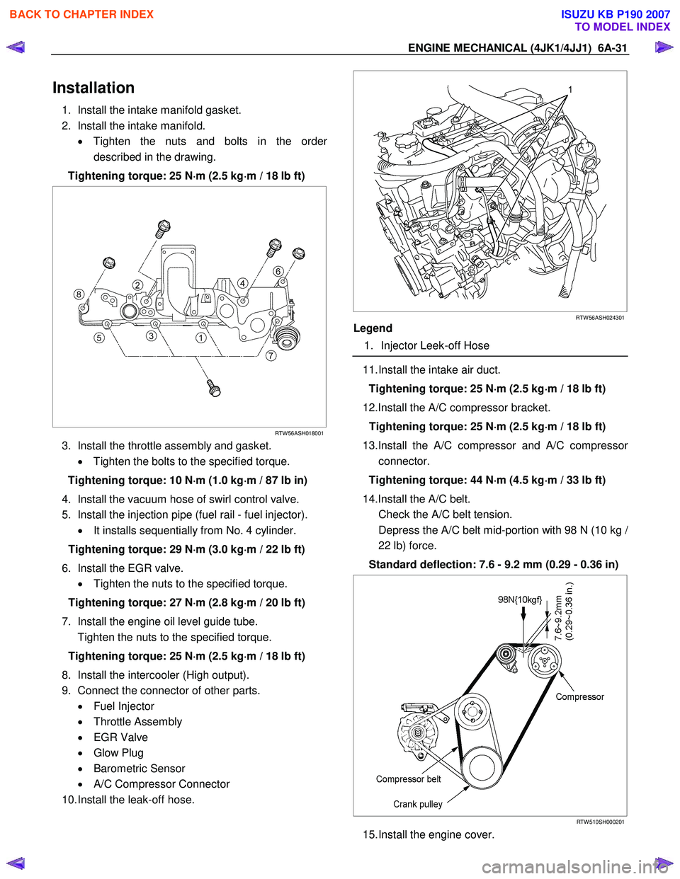
2. Install the intake manifold. • Tighten the nuts and bolts in the orde
r
described in the drawing.
Tightening torque: 25 N ⋅
⋅⋅
⋅
m (2.5 kg ⋅
⋅⋅
⋅
m / 18 lb ft)
RTW 56ASH018001
3. Install the throttle assembly and gasket.
• Tighten the bolts to the specified torque.
Tightening torque: 10 N ⋅
⋅⋅
⋅
m (1.0 kg ⋅
⋅⋅
⋅
m / 87 lb in)
4. Install the vacuum hose of swirl control valve.
5. Install the injection pipe (fuel rail - fuel injector). • It installs sequentially from No. 4 cylinder.
Tightening torque: 29 N ⋅
⋅⋅
⋅
m (3.0 kg ⋅
⋅⋅
⋅
m / 22 lb ft)
6. Install the EGR valve. • Tighten the nuts to the specified torque.
Tightening torque: 27 N ⋅
⋅⋅
⋅
m (2.8 kg ⋅
⋅⋅
⋅
m / 20 lb ft)
7. Install the engine oil level guide tube.
Tighten the nuts to the specified torque.
Tightening torque: 25 N ⋅
⋅⋅
⋅
m (2.5 kg ⋅
⋅⋅
⋅
m / 18 lb ft)
8. Install the intercooler (High output).
9. Connect the connector of other parts. • Fuel Injector
• Throttle Assembly
• EGR Valve
• Glow Plug
• Barometric Sensor
• A/C Compressor Connector
10. Install the leak-off hose.
RTW 56ASH024301
Legend
1. Injector Leek-off Hose
11. Install the intake air duct.
Tightening torque: 25 N ⋅
⋅⋅
⋅
m (2.5 kg ⋅
⋅⋅
⋅
m / 18 lb ft)
12.Install the A/C compressor bracket. Tightening torque: 25 N ⋅
⋅⋅
⋅
m (2.5 kg ⋅
⋅⋅
⋅
m / 18 lb ft)
13.Install the A/C compressor and A/C compresso
r
connector.
Tightening torque: 44 N ⋅
⋅⋅
⋅
m (4.5 kg ⋅
⋅⋅
⋅
m / 33 lb ft)
14.Install the A/C belt.
Check the A/C belt tension.
Depress the A/C belt mid-portion with 98 N (10 kg
/
22 lb) force.
Standard deflection: 7.6 - 9.2 mm (0.29 - 0.36 in)
RTW 510SH000201
15. Install the engine cover.
BACK TO CHAPTER INDEX
TO MODEL INDEX
ISUZU KB P190 2007
Page 1396 of 6020
6A-36 ENGINE MECHANICAL (4JK1/4JJ1)
Inspection
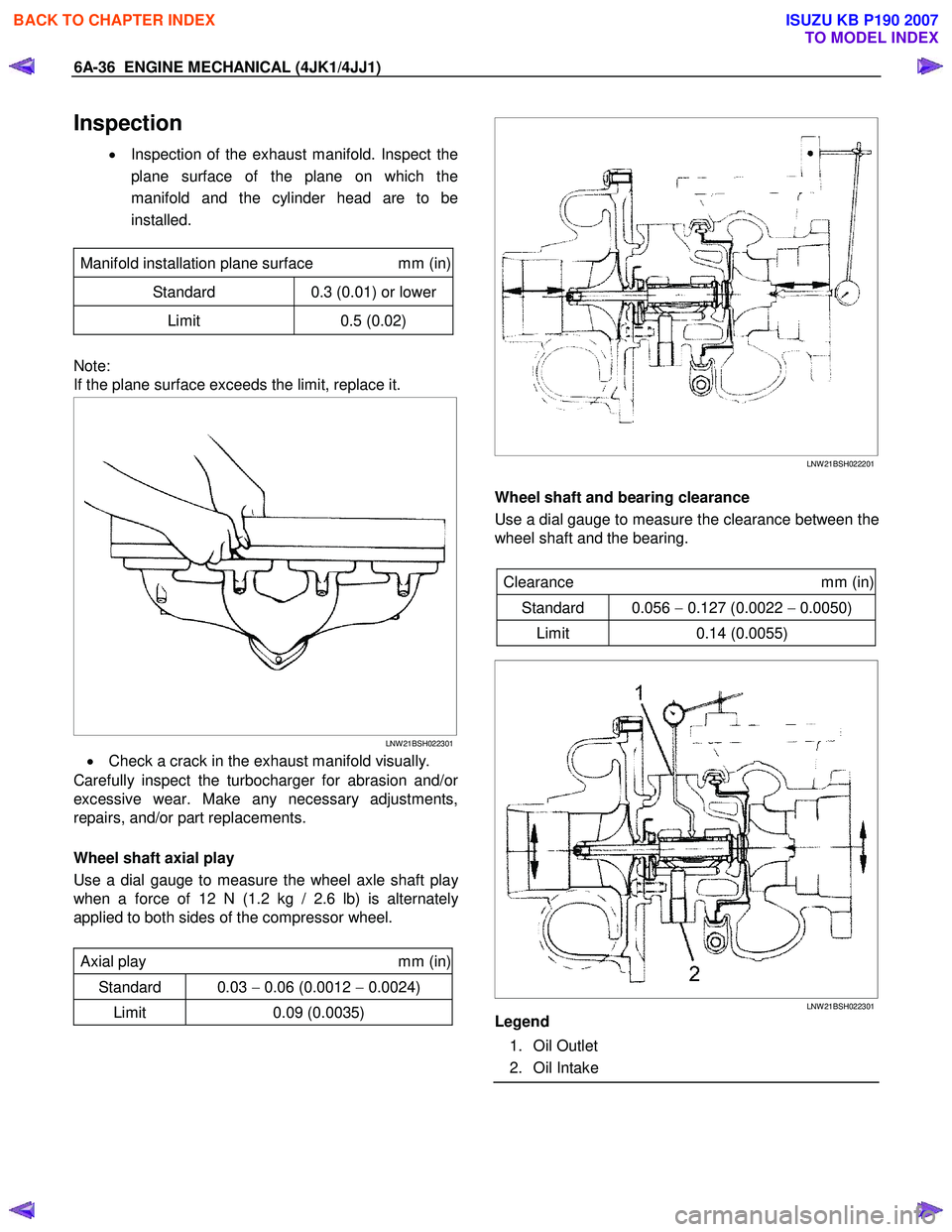
• Inspection of the exhaust manifold. Inspect the
plane surface of the plane on which the
manifold and the cylinder head are to be
installed.
Manifold installation plane surface mm (in)
Standard 0.3 (0.01) or lower
Limit 0.5 (0.02)
Note:
If the plane surface exceeds the limit, replace it.
LNW 21BSH022301
• Check a crack in the exhaust manifold visually.
Carefully inspect the turbocharger for abrasion and/o
r
excessive wear. Make any necessary adjustments,
repairs, and/or part replacements.
Wheel shaft axial play
Use a dial gauge to measure the wheel axle shaft pla
y
when a force of 12 N (1.2 kg / 2.6 lb) is alternately
applied to both sides of the compressor wheel.
Axial play mm (in)
Standard 0.03 − 0.06 (0.0012 − 0.0024)
Limit 0.09 (0.0035)
LNW 21BSH022201
Wheel shaft and bearing clearance
Use a dial gauge to measure the clearance between the
wheel shaft and the bearing.
Clearance mm (in)
Standard 0.056 − 0.127 (0.0022 − 0.0050)
Limit 0.14 (0.0055)
LNW 21BSH022301
Legend
1. Oil Outlet
2. Oil Intake
BACK TO CHAPTER INDEX
TO MODEL INDEX
ISUZU KB P190 2007
Page 1404 of 6020
6A-44 ENGINE MECHANICAL (4JK1/4JJ1)
3. Place a vernier caliper on the end of the control
rod of actuator. Release the vacuum pressure and
check the control rod moves. Measure the length
of the control rod moving.
Standard length mm (in)
12 (0.48)
Installation
1. Install the gasket and the turbocharger to the
exhaust manifold. Temporarily tighten nuts.
2. Install the oil feed and return pipe and temporaril
y
tighten.
3. Tighten the turbocharger nuts to the specified torque.
Tightening torque: 27 N ⋅
⋅⋅
⋅
m (2.8 kg ⋅
⋅⋅
⋅
m / 20 lb ft)
4. Tighten the oil feed and return pipe bolts and nuts to the specified torque.
Tightening torque (Turbocharger side): 10 N ⋅
⋅⋅
⋅
m (1.0 kg ⋅
⋅⋅
⋅
m / 87 lb in)
Tightening torque (Crank case side): 25 N ⋅
⋅⋅
⋅
m (2.5 kg ⋅
⋅⋅
⋅
m / 18 lb ft)
5. Install the water feed and return pipe to the turbocharger.
Tightening torque: 25 N ⋅
⋅⋅
⋅
m (2.5 kg ⋅
⋅⋅
⋅
m / 18 lb ft)
6. Install the heat protector to the turbocharger. Tightening torque: 10 N ⋅
⋅⋅
⋅
m (1.0 kg ⋅
⋅⋅
⋅
m / 18 lb ft)
7. Install the turbocharger bracket.
8. Install the catalyst converter.
Tighten the nuts to the specified torque.
Tightening torque: 27 N ⋅
⋅⋅
⋅
m (2.8 kg ⋅
⋅⋅
⋅
m / 20 lb ft)
9. Install the mud cover of front RH fender skirt (4 ×4
only).
10. Install the front exhaust pipe.
Tighten the nuts to the specified torque.
Tightening torque
Exhaust Manifold Side: 67 N⋅
⋅⋅
⋅m (6.8 kg⋅
⋅⋅
⋅m / 49 lb ft)
Exhaust Pipe Side: 43 N
⋅
⋅⋅
⋅
m (4.4 kg ⋅
⋅⋅
⋅
m / 32lb ft)
11. Install the intercooler. • Install the intercooler.
• Install the two intake hoses.
• Connect the BARO sensor harness connector.
12. Install the intake duct between the turbocharge
r
and the air cleaner.
Tightening torque: 6 N ⋅
⋅⋅
⋅
m (0.6 kg ⋅
⋅⋅
⋅
m / 52 lb in)
13.Replenish the coolant.
BACK TO CHAPTER INDEX
TO MODEL INDEX
ISUZU KB P190 2007