2007 ISUZU KB P190 engine
[x] Cancel search: enginePage 2469 of 6020
ENGINE LUBRICATION 6G-5
Inspection and Repair
CAUTION: Make necessary correction or parts
replacement if wear, damage or any other abnormal
conditions are found through inspection.
Body and Gears
The pump assembly must be replaced if one or more of the
conditions below is discovered during inspection:
Indentation of gear pair - Use feeler strip and straight edge.
Dimension: 0.03 mm to 0.10 mm
(0.0012 to 0.0039 in)
Oil Strainer
Check the oil strainer for cracking and scoring. If cracking and
scoring are found, the oil strainer must be replaced.
Reassembly
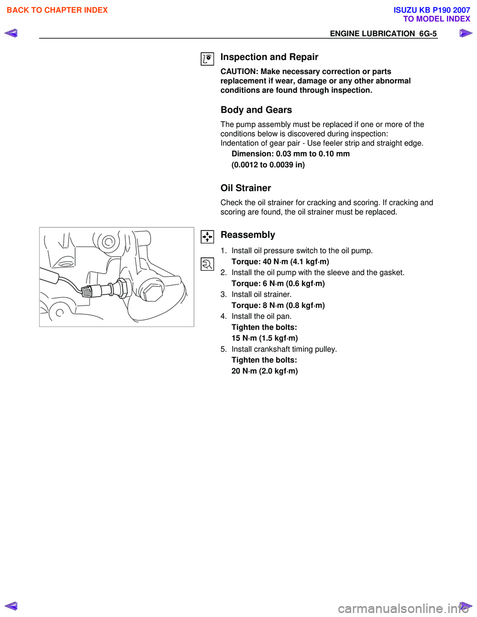
1. Install oil pressure switch to the oil pump.
Torque: 40 N ⋅
⋅⋅
⋅
m (4.1 kgf ⋅
⋅⋅
⋅
m)
2. Install the oil pump with the sleeve and the gasket.
Torque: 6 N ⋅
⋅⋅
⋅
m (0.6 kgf ⋅
⋅⋅
⋅
m)
3. Install oil strainer.
Torque: 8 N ⋅
⋅⋅
⋅
m (0.8 kgf ⋅
⋅⋅
⋅
m)
4. Install the oil pan.
Tighten the bolts:
15 N ⋅
⋅⋅
⋅
m (1.5 kgf ⋅
⋅⋅
⋅
m)
5. Install crankshaft timing pulley.
Tighten the bolts:
20 N ⋅
⋅⋅
⋅
m (2.0 kgf ⋅
⋅⋅
⋅
m)
BACK TO CHAPTER INDEX
TO MODEL INDEX
ISUZU KB P190 2007
Page 2470 of 6020
6G-6 ENGINE LUBRICATION
Oil Pan
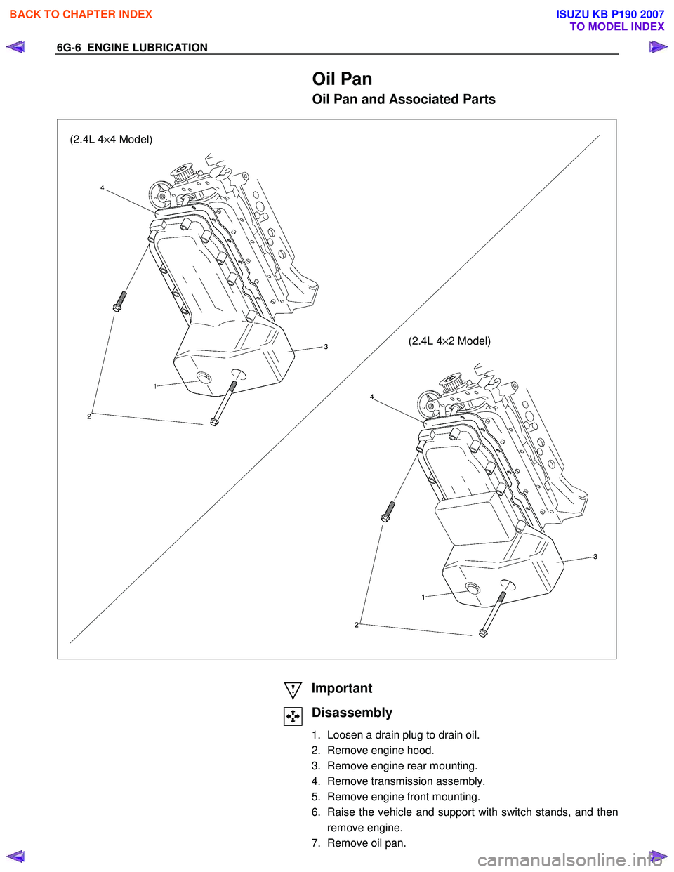
Oil Pan and Associated Parts
(2.4L 4×4 Model)
(2.4L 4×2 Model)
Important
Disassembly
1. Loosen a drain plug to drain oil.
2. Remove engine hood.
3. Remove engine rear mounting.
4. Remove transmission assembly.
5. Remove engine front mounting.
6. Raise the vehicle and support with switch stands, and then remove engine.
7. Remove oil pan.
BACK TO CHAPTER INDEX
TO MODEL INDEX
ISUZU KB P190 2007
Page 2471 of 6020
ENGINE LUBRICATION 6G-7
Inspection and Repair
CAUTION: Make necessary correction or parts replacement if wear, damage or any other
abnormal conditions are found through
inspection.
Reassembly
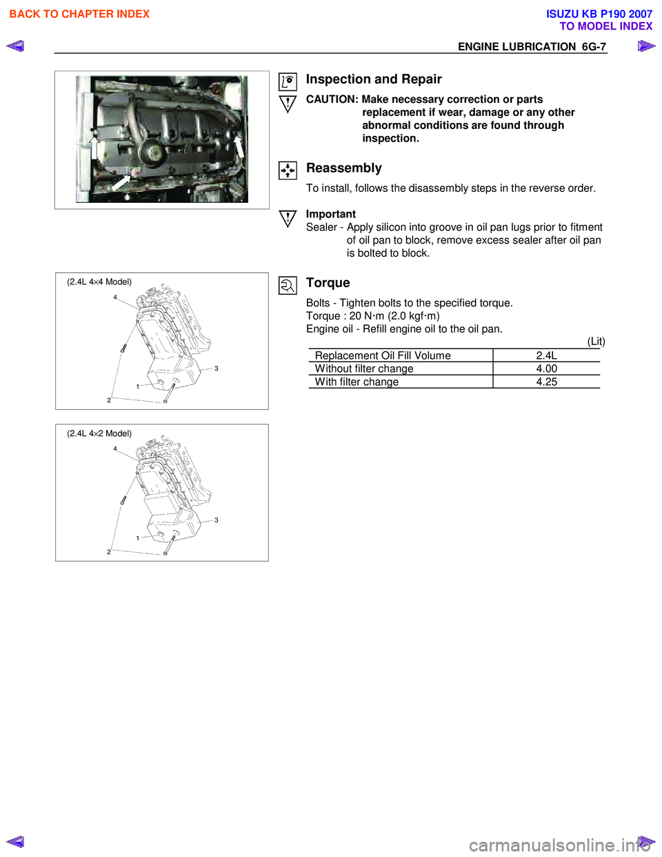
To install, follows the disassembly steps in the reverse order.
Important
Sealer - Apply silicon into groove in oil pan lugs prior to fitment of oil pan to block, remove excess sealer after oil pan
is bolted to block.
(2.4L 4 ×4 Model)
4
3
1
2
(2.4L 4 ×2 Model)
4
3
1
2
Torque
Bolts - Tighten bolts to the specified torque.
Torque : 20 N �xm (2.0 kgf �xm)
Engine oil - Refill engine oil to the oil pan. (Lit)
Replacement Oil Fill Volume 2.4L
W ithout filter change 4.00
W ith filter change 4.25
BACK TO CHAPTER INDEX
TO MODEL INDEX
ISUZU KB P190 2007
Page 2472 of 6020
EN G IN E SPEED C O NTR O L S Y STEM ( C 24SE) 6 H
SECTION 6H
ENGINE SPEED CONTROL SYSTEM (C24SE)
TABLE OF CONTENTS
Sevice Precaution ....................................................................................................... ..... 6 H - 1
PA
GE
Accele rator Pedal Control Cable .................................................................................... 6 H - 2
Removal ................................................................................... ........................................ 6 H - 2
Inspection ................................................................................... ..................................... 6 H - 3
Installation ................................................................................... ..................................... 6H - 3
BACK TO CHAPTER INDEX
TO MODEL INDEX
ISUZU KB P190 2007
Page 2474 of 6020
6H-2 ENGINE SPEED CONTROL SYSTEM (C24SE)
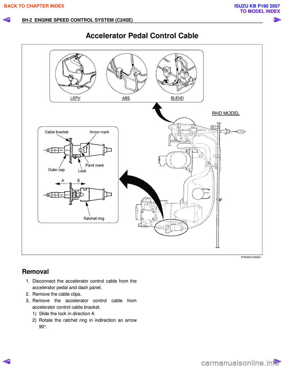
Accelerator Pedal Control Cable
RHD MODEL
RTW 46HLF000501
Removal
1. Disconnect the accelerator control cable from the
accelerator pedal and dash panel.
2. Remove the cable clips.
3. Remove the accelerator control cable from
accelerator control cable bracket.
1) Slide the lock in direction A
2) Rotate the ratchet ring in indirection an arro
w
90 °.
BACK TO CHAPTER INDEX
TO MODEL INDEX
ISUZU KB P190 2007
Page 2475 of 6020
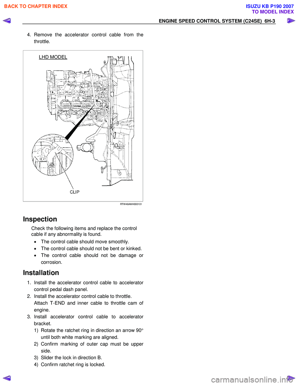
4. Remove the accelerator control cable from the
throttle.
LHD MODEL
RTW 46AMH000101
Inspection
Check the following items and replace the control
cable if any abnormality is found.
• The control cable should move smoothly.
• The control cable should not be bent or kinked.
• The control cable should not be damage o
r
corrosion.
Installation
1. Install the accelerator control cable to accelerator
control pedal dash panel.
2. Install the accelerator control cable to throttle.
Attach T-END and inner cable to throttle cam o
f
engine.
3. Install accelerator control cable to accelerato
r
bracket.
1) Rotate the ratchet ring in direction an arrow 90 °
until both white marking are aligned.
2) Confirm marking of outer cap must be uppe
r
side.
3) Slider the lock in direction B.
4) Confirm ratchet ring is locked.
EN
GIN E SPEED CONTR O L SY STEM (C 24SE) 6H-3
BACK TO CHAPTER INDEX
TO MODEL INDEX
ISUZU KB P190 2007
Page 2479 of 6020
Section 6A1 Engine Mechanical ................................................................................... 2480 PAGE
Section 6A1 Engine Mechanical Update....................................................................... 2778
Section 6C1-1 Engine Management General Information ......................................... 3243
Section 6C1-2 Engine Management Diagnostics........................................................ 3279
Section 6C1-3 Engine Management Service Operations ........................................... 3525
Section 6D1-1 Charging System V6 ............................................................................ 3588
SECTION 6
ENGINE
TA BLE OF CONTENTS
Section 6D1-3 Battery V6 ............................................................................................. 3641
Section 6E1 Powertrain Interface Module V6 .............................................................. 3662
HFV6 MODEL
ENGINE HFV6
Section 6B Engine Cooling .......................................................................................... 3136
Section 6C Fuel System V6 .......................................................................................... 3203
Section 6 D1-2 St art ing Syste m V 6 ............................................................................... 36 09
Section 6F Exhaust System V6 .................................................................................... 3749
BACK TO CHAPTER INDEX
TO MODEL INDEX
ISUZU KB P190 2007
Page 2480 of 6020
Engine Mechanical – V6 Page 6A1–1
6A1
Engine Mechanical – V6
ATTENTION
Before performing any service operation or other procedure described in this Section, refer to 1.1
WARNING, CAUTION and NOTES for correct workshop practices with regard to safety and/or property
damage.
1 General Information ............................................................................................................ ...................8
1.1 WARNING, CAUTION and NOTES .................................................................................................... ................... 8
Definition of WARNING, CAUTION and NOTE Statements ............................................................................. .... 8
WARNING defined ............................................................................................................................................. 8
CAUTION defined .............................................................................................................................................. 8
NOTE defined..................................................................................................................................................... 9
1.2 Engine Components .............................................................................................................................................. 9
Major Component Assemblies..................................................................................................... ......................... 9
Intake Manifold Assembly ................................................................................................................................... 10
Engine Front Cover.............................................................................................................................................. 12
Camshaft Timing Components ..................................................................................................... ...................... 13
Camshaft Cover Assembly.................................................................................................................................. 14
Cylinder Head Assembly ..................................................................................................................................... 15
Oil Pump ............................................................................................................................................................... 16
Engine Block Assembly .......................................................................................................... ............................ 17
Pistons, Rings, Bearing and Connecting Rod ..................................................................................... .............. 18
Oil Pan Assembly................................................................................................................................................. 19
Oil Filter Assembly .............................................................................................................................................. 20
1.3 Engine Serial Number........................................................................................................... ............................... 20
1.4 Engine Construction............................................................................................................................................ 21
Cylinder Block ...................................................................................................................................................... 21
Cylinder Heads ................................................................................................................. .................................... 21
Crankshaft ............................................................................................................................................................ 22
Pistons, Pins and Connecting Rods .............................................................................................. .................... 22
Camshaft Drive System ....................................................................................................................................... 22
1.5 Engine Lubrication System ...................................................................................................... ........................... 24
Lubrication Description....................................................................................................................................... 24
1.6 Service Notes ....................................................................................................................................................... 24
Cleanliness and Care........................................................................................................... ................................ 24
Replacing Engine Gaskets ....................................................................................................... ........................... 24
Re-Using Gaskets and Applying Sealants......................................................................................... ............... 24
Separating Components................................................................................................................................... 24
Cleaning Gasket Surfaces................................................................................................................................ 24
Assembling Components .......................................................................................................... ....................... 25
Use of Room Temperature Vulcanising and Anaerobic Sealer....................................................................... .25
Room Temperature Vulcanising Sealer............................................................................................................ 25
Anaerobic Sealer .............................................................................................................................................. 25
Pipe Joint Compound ............................................................................................................ ........................... 26
Separating Parts .................................................................................................................................................. 26
Tools and Equipment ............................................................................................................ .............................. 26
Fasteners .............................................................................................................................................................. 27
Clamp Load ..................................................................................................................... ................................. 27
Torque Angle and Torque to Yield Fasteners..................................................................................... .............. 27
2 Diagnosis ..............................................................................................................................................28
2.1 Engine Diagnosis ............................................................................................................... .................................. 28
2.2 Symptoms............................................................................................................................................................. 28
Strategy Based Diagnosis ....................................................................................................... ............................ 28
BACK TO CHAPTER INDEX
TO MODEL INDEX
ISUZU KB P190 2007