Page 640 of 6020
BRAKE CONTROL SYSTEM 5A-47
ABS Warning Lamp ON Steady
Step Action Value(s) Yes No
1 1. Check the ABS warning lamp lighting circuit for a
short.
2. If a problem found, repair as necessary. W as a problem found? - Go to Step 3 Go to Step 2
2 1. Check the ABS warning lamp lighting circuit at the
meter for a short. Refer to METER, W ARNING
LIGHT AND INDICATOR LIGHT in 8 section.
2. If a problem is found, repair or replace the meter. W as a problem found? - Go to Step 3 Go to Step 4
3 1. Connect all connectors.
2. Ignition “ON”, engine “OFF”.
3. W ait for about 10 seconds.
4. Observe the ABS warning lamp. Is the ABS warning lamp turned “OFF”? - Verify repair Go to Step 4
4 Replace EHCU.
Note: Check the EHCU type for specification, the
EHCU is replaced.
(Specification; 2W D or 4W D Model)
Is the action complete? - Verify repair -
BACK TO CHAPTER INDEX
TO MODEL INDEX
ISUZU KB P190 2007
Page 771 of 6020

PARKING BRAKE SYSTEM 5D-1
Service Precaution
Service Precaution
WARNING: THIS VEHICLE HAS A SUPPLEMENTAL
RESTRAINT SYSTEM (SRS). REFER TO THE SRS
COMPONENT AND WIRING LOCATION VIEW IN
ORDER TO DETERMINE WHETHER YOU ARE
PERFORMING SERVICE ON OR NEAR THE SRS
COMPONENTS OR THE SRS WIRING. WHEN YOU
ARE PERFORMING SERVICE ON OR NEAR THE
SRS COMPONENTS OR THE SRS WIRING, REFER
TO THE SRS SERVICE INFORMATION. FAILURE TO
FOLLOW WARNINGS COULD RESULT IN
POSSIBLE AIR BAG DEPLOYMENT, PERSONAL
INJURY, OR OTHERWISE UNNECESSARY SRS
SYSTEM REPAIRS.
CAUTION: Always use the correct fastener in the
proper location. When you replace a fastener, use
ONLY the exact part number for that application.
ISUZU/GM will call out those fasteners that require
a replacement after removal. ISUZU/GM will also
call out the fasteners that require thread lockers o
r
thread sealant. UNLESS OTHERWISE SPECIFIED,
do not use supplemental coatings (paints, greases,
or other corrosion inhibitors) on threaded fasteners
or fastener joint interfaces. Generally, such
coatings adversely affect the fastener torque and
the joint clamping force, and may damage the
fastener. When you install fasteners, use the
correct tightening sequence and specifications.
Following these instructions can help you avoid
damage to parts and systems.
General Description
Pulling up the parking brake lever by hand will set the
parking brake. By means of a ratchet type lock, the
lever can be held in that position until it is released. The
position of the lever is transmitted through cable/leve
r
systems to the rear wheels. These parts are designed
to obtain sufficient braking force even when parking on
slopes. W hen the parking brake is set, or when the
ignition SW is in the “ON” position, the brake warning
light illuminates. The rear wheel parking brake is a
leading-trailing brake (mechanical inside expansion
type) built in the rear drum brake. Parking brake
adjustment is made through the adjusting hole (bored
through back plate). Parking brake lever stroke should
be adjusted to 8 −14 notches with 294N (30 kg / 66 lb)
(bench seat) or 6 −9 notches with 294N (30 kg / 66 lb)
(bucket seat). Refer to “Parking Brake Adjustment” in
this section.
BACK TO CHAPTER INDEX
TO MODEL INDEX
ISUZU KB P190 2007
Page 846 of 6020

ENGINE MECHANICAL 6A – 41
Coolant Replenishment
Warning:
When the coolant is heated to a high temperature, be
sure not to loosen or remove the rediator cap.
Otherwise you might get scalded by hot vapor or
boiling water.
To open the radiator cap, put a piece of thick cloth on
the cap and loosen the cap slowly to reduce the
pressure when the coolant has become cooler.
1. Open rediator cap pour coolant up to filler neck
2. Pour coolant into reservoir tank up to "MAX" line
3. Tighten radiator cap and start the engine. After idling for 2 to 3 minutes, stop the engine and reopen radiator
cap. If the water level is lower, replenish.
4. After replenish the coolant tighten radiator cap, warm up the engine at about 2000 rpm. Set heater
adjustment to the highest temperature position, and let
the coolant circulate also into heater water system.
5. Check to see the thermometer, continuously idling 5 minutes and stop the engine.
6. W hen the engine has been cooled, check filler neck for water level and replenish if required. Should extreme
shortage of coolant is found, check the coolant system
and reservoir tank hose for leakage.
7. Pour coolant into the reservoir tank up to "MAX" line.
Coolant Capacity lit (US/UK gal)
4JA1 / TC 9.4 (2.5 / 2.1)
4JH1TC M/T: 10.1 (2.7 / 2.2)
A/T: 10.0 (2.6 / 2.2)
Engine Warm-Up
After completing the required maintenance procedures,
start the engine and allow it to idle until it is warm.
Check the following:
1. Engine idling speed.
2. Engine noise level.
3. Engine lubricating system and cooling system. Carefully check for oil and coolant leakage.
4. Clutch engagement.
5. Transmission operation.
6. Indicator warning light operation.
BACK TO CHAPTER INDEX
TO MODEL INDEX
ISUZU KB P190 2007
Page 968 of 6020
6C – 4 FUEL SYSTEM
FUEL FILTER AND WATER SEPARATOR
As the inside of the injection pump is lubricated by the fuel which it is pumping, the fuel must be perfectly clean. The
fuel filter and the water separator remove water particles and other foreign material from the fuel before it reaches
the injection pump.
The water separator has an internal float. W hen the float reaches the specified level, a warning light comes on to
remind you to drain the water from the water separator.
A diaphragm type priming pump is installed at the top of the fuel filter. It is used during the air bleeding procedures.
(Except EURO III model)
RTW 36CLF000701
BACK TO CHAPTER INDEX
TO MODEL INDEX
ISUZU KB P190 2007
Page 1522 of 6020

6A-162 ENGINE MECHANICAL (4JK1/4JJ1)
Removal
1. Remove the oil pressure SW .
2. Remove the nipple; oil gallery.
3. Remove the nipple; oil pressure warning SW and gasket.
Inspection
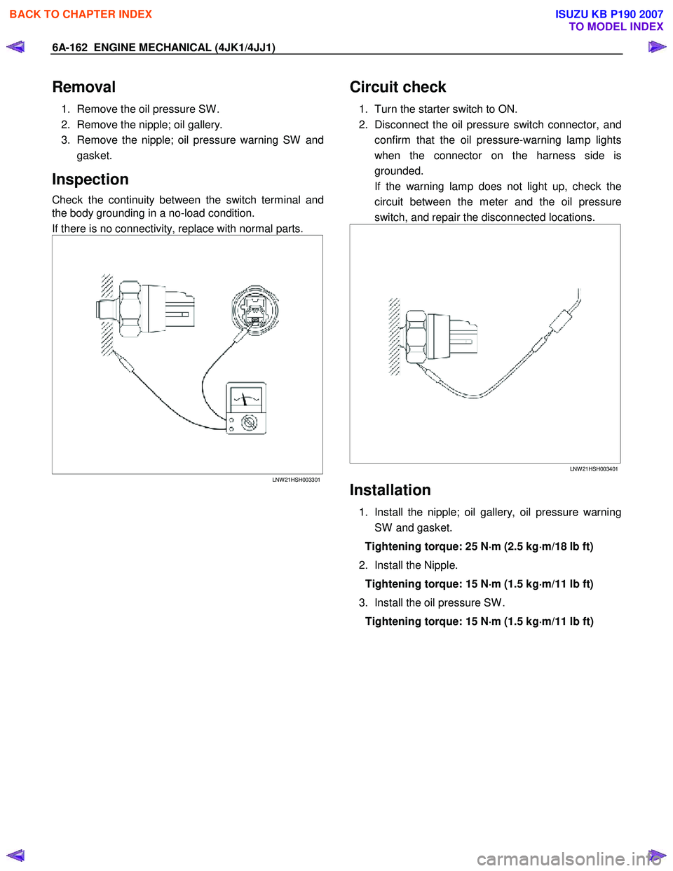
Check the continuity between the switch terminal and
the body grounding in a no-load condition.
If there is no connectivity, replace with normal parts.
LNW 21HSH003301
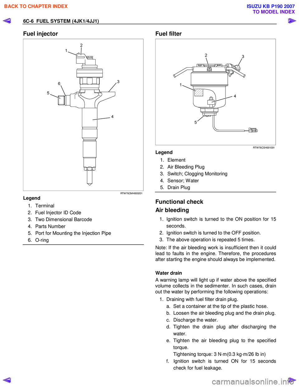
Circuit check
1. Turn the starter switch to ON.
2. Disconnect the oil pressure switch connector, and confirm that the oil pressure-warning lamp lights
when the connector on the harness side is
grounded.
If the warning lamp does not light up, check the circuit between the meter and the oil pressure
switch, and repair the disconnected locations.
LNW 21HSH003401
Installation
1. Install the nipple; oil gallery, oil pressure warning
SW and gasket.
Tightening torque: 25 N ⋅
⋅⋅
⋅
m (2.5 kg ⋅
⋅⋅
⋅
m/18 lb ft)
2. Install the Nipple. Tightening torque: 15 N ⋅
⋅⋅
⋅
m (1.5 kg ⋅
⋅⋅
⋅
m/11 lb ft)
3. Install the oil pressure SW . Tightening torque: 15 N ⋅
⋅⋅
⋅
m (1.5 kg ⋅
⋅⋅
⋅
m/11 lb ft)
BACK TO CHAPTER INDEX
TO MODEL INDEX
ISUZU KB P190 2007
Page 1547 of 6020

6C-6 FUEL SYSTEM (4JK1/4JJ1)
Fuel injector
RTW 76CMH000201
Legend
1. Terminal
2. Fuel Injector ID Code
3. Two Dimensional Barcode
4. Parts Number
5. Port for Mounting the Injection Pipe
6. O-ring
Fuel filter
RTW 76CSH001001
Legend
1. Element
2. Air Bleeding Plug
3. Switch; Clogging Monitoring
4. Sensor; W ater
5. Drain Plug
Functional check
Air bleeding
1. Ignition switch is turned to the ON position for 15 seconds.
2. Ignition switch is turned to the OFF position.
3. The above operation is repeated 5 times.
Note: If the air bleeding work is insufficient then it could
lead to faults in the engine. Therefore, the procedures
after starting the engine should always be implemented.
Water drain
A warning lamp will light up if water above the specified
volume collects in the sedimenter. In such cases, drain
out the water by performing the following operations:
1. Draining with fuel filter drain plug. a. Set a container at the tip of the plastic hose.
b. Loosen the air bleeding plug and the drain plug.
c. Discharge the water.
d. Tighten the drain plug after discharging the water.
e. Tighten the air bleeding plug to the specified torque.
Tightening torque: 3 N ⋅m(0.3 kg ⋅m/26 lb in)
f. Ignition switch is turned ON for 15 seconds check for fuel leakage.
BACK TO CHAPTER INDEX
TO MODEL INDEX
ISUZU KB P190 2007
Page 1580 of 6020
FUEL SYSTEM (4JK1/4JJ1) 6C-39
Fuel Sedimenter Switch
Inspection
1. Check that there is continuity between the switch
connector terminals when the float in the fuel
sedimenter is above the water drain line.
2. Turn on the ignition switch, remove the fuel sedimenter connector, and connect the terminals
of the connectors on the harness side. Confirm
that the sedimenter warning lamp lights up.
If abnormalities are detected during the check, replace
the switch parts and carry out repairs in case o
f
defective connection between circuits or short circuits.
RTW 76CSH001101
Legend
1. Sensor
2. Connector on The Vehicle Side
3. Harness
4. Drain Valve
BACK TO CHAPTER INDEX
TO MODEL INDEX
ISUZU KB P190 2007
Page 1595 of 6020
ENGINE ELECTRICAL (4JK1/4JJ1) 6D-7
Diagnosis
On-vehicle Inspection
The charging system warning light tells the vehicle
operator of possible problems with the system.
W hen the ignition switch is moved to the ON position,
the light turns on. The light turns off immediately afte
r
the engine is started. If the light turns on during engine
operation, there is a problem with the charging system.
Perform the checks described below.
1. Check the belt (broken or loose).
2. Check the harness connectors (loose o
r
disconnected).
3. W ith the engine off, turn the ignition switch to the ON position. If the warning lamp does not light,
remove the harness connector from the generator.
Ground the connector IG terminal. The lamp
should light. If it does not, the bulb is burned out.
Replace the bulb.
4. Start the engine. If the warning lamp remains on, the generator must be repaired or replaced.
BACK TO CHAPTER INDEX
TO MODEL INDEX
ISUZU KB P190 2007