2007 ISUZU KB P190 check transmission fluid
[x] Cancel search: check transmission fluidPage 3202 of 6020
Engine Cooling – V6 Engine Page 6B1–67
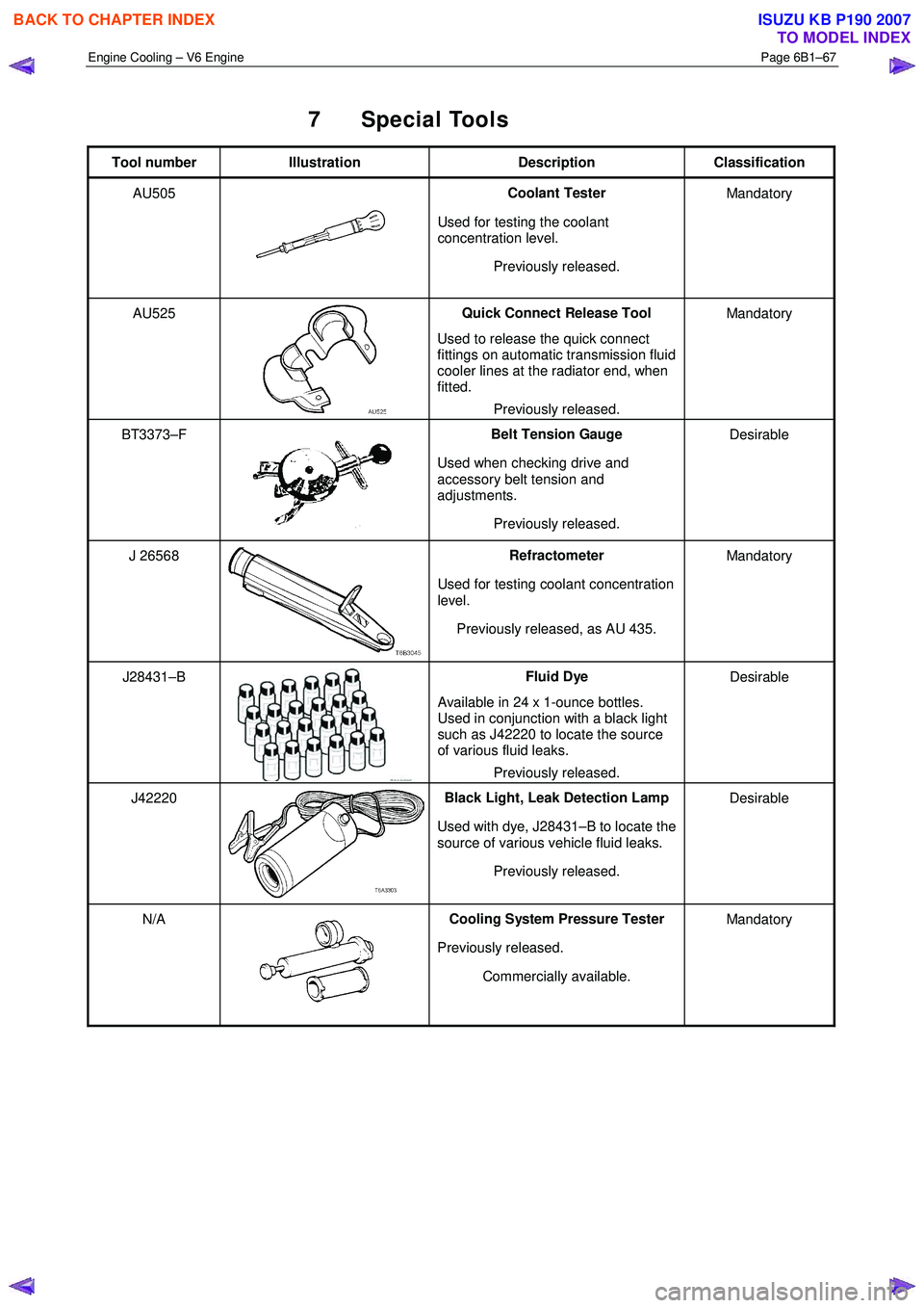
7 Special Tools
Tool number Illustration Description Classification
AU505
Coolant Tester
Used for testing the coolant
concentration level.
Previously released. Mandatory
AU525
Quick Connect Release Tool
Used to release the quick connect
fittings on automatic transmission fluid
cooler lines at the radiator end, when
fitted.
Previously released. Mandatory
BT3373–F
Belt Tension Gauge
Used when checking drive and
accessory belt tension and
adjustments.
Previously released. Desirable
J 26568 Refractometer
Used for testing coolant concentration
level.
Previously released, as AU 435. Mandatory
J28431–B Fluid Dye
Available in 24 x 1-ounce bottles.
Used in conjunction with a black light
such as J42220 to locate the source
of various fluid leaks.
Previously released. Desirable
J42220 Black Light, Leak Detection Lamp
Used with dye, J28431–B to locate the
source of various vehicle fluid leaks.
Previously released. Desirable
N/A Cooling System Pressure Tester
Previously released. Commercially available. Mandatory
BACK TO CHAPTER INDEX
TO MODEL INDEX
ISUZU KB P190 2007
Page 3765 of 6020
Automatic Transmission – 4L60E – General Information Page 7C1–5
Clean and Inspect
Do not use solvents on neoprene seals,
composition faced clutch plates or thrust
washers as damage to parts may occur.
After complete disassembly of a component, wash all metal parts in a clean solvent and dry with compressed air. Blow
oil passages out and check to make sure they are not obstructed, small passages should be checked with tag wire. All
parts should be inspected to determine if replacement is required.
Pay particular attention to the following:
• Inspect linkage and pivot points for excessive wear.
• Bearing and thrust surfaces of all parts should be checked for excessive wear and scoring.
• Check for broken seal rings, damaged ring lands and damaged threads.
• Inspect seals for damage.
• Mating surfaces of castings should be checked for burrs. Irregularities may be removed by lapping the surface with
emery paper laid on a flat surface, such as a piece of plate glass.
• Castings should be checked for cracks and porosity.
1.3 7C2 Automatic Transmission – 4L60E –
Electrical Diagnosis
For transmissions fitted to V6 engines, the electrical diagnosis is in this Section. A new electrical circuit and control
module has been introduced for automatic transmissions fitted to the V6 engines.
1.4 7C3 Automatic Transmission – 4L60E – Hydraulic and Mechanical Diagnosis
Information contained in 7C3 Automatic Transmission – 4L60E – Hydraulic and Mechanical Diagnosis will assist in the
diagnosis of the mechanical and hydraulic components in the 4L60E automatic transmission, while the transmission
remains installed on the vehicle.
Examples of the type of diagnostic information contained within this section are:
• transmission functional test,
• line pressure information,
• transmission fluid diagnosis,
• symptom diagnosis and
• shift speed charts.
1.5 7C4 Automatic Transmission – 4L60E –
On-vehicle Servicing
Information in 7C4 Automatic Transmission – 4L60E – On-vehicle Servicing covers transmission fluid level checking, as
well as specific information for servicing some components while the transmission remains installed on the vehicle. This
Section also covers the transmission removal and reinstallation to the vehicle.
BACK TO CHAPTER INDEX
TO MODEL INDEX
ISUZU KB P190 2007
Page 3772 of 6020
Automatic Transmission – 4L60E – General Information Page 7C1–12
General Definition
Check Ball A spherical, hydraulically controlled component (usually of steel) that either seals or
opens fluid circuits. It is also referred to as a check valve.
Clutch Pack An assembly of components generally consisting of clutch plates, an apply plate and a
backing plate.
Clutch Plate A hydraulically activated component that has two basic designs: (1) all steel, or (2) a
steel core with friction material bonded to one or two sides of the plate.
Control Valve Body A machined metal casting that contains valve trains and other hydraulically controlled components that shift the transmission.
Coupling Speed The speed at which a vehicle is travelling and no longer requires torque multiplication through the torque converter. At this point, the stator 'free wheels' to allow fluid leaving
the turbine to flow directly to the pump. (Also see Torque Converter).
De-energise(d) To interrupt the electrical current that flows to an electronically controlled device,
making it electrically inoperable.
Direct Drive A condition in a gears set where the input speed and input torque equals the output
speed and output torque. The gear ratio through the gear set is 1:1.
Downshift A change in a gear ratio where both input speed and torque increases.
Duty Cycle In reference to an electronically controlled solenoid, it is the amount of time (expressed
as a percentage) that current flows through the solenoid coil.
Energise(d) To supply a current to an electronically controlled device, enabling it to perform its
designed function.
Engine Compression Braking A condition where compression from the engine is used with the transmission to decrease vehicle speed.
Exhaust The release of fluid pressure from a hydraulic circuit. (The words 'exhausts' and
'exhausting' are also used and have the same intended meaning.)
Fail-safe Mode A condition whereby a component (i.e. engine or transmission) will partially function even if its electrical circuit is disabled.
Fluid In this Section of the Service Manual, 'fluid' refers primarily to automatic transmission
fluid (or ATF) and, for the Hydra-matic 4L60E transmission, the only recommended
fluid is Dexron
III.
Fluid Pressure A pressure that is consistent throughout a given fluid circuit.
Force A measurable effort that is exerted on an object (component).
Freewheeling A condition where power is lost through a driving or holding device (i.e. roller or sprag
clutches).
Friction Material A heat and wear resistant fibrous material, bonded to clutch plates and bands.
Gear A round, toothed device that is used for transmitting torque through other components.
Gear Range A specific speed to torque ratio at which the transmission is operating (i.e. 1st gear,
2nd gear etc.).
Gear Ratio Revolutions of an input gear as compared to the revolutions of an output gear. It can
also be expressed as the number of teeth on a gear as compared to the number of
teeth on a gear that it is in mesh with.
Hydraulic Circuit A fluid passage which often includes the mechanical components in that circuit
designed to perform a specific function.
Input A starting point for torque, revolutions or energy into another component of the
transmission.
Internal Gear The outermost member of a gear set that has gear teeth in constant mesh with the
planetary pinion gears of the gear set.
Land (Valve Land) The larger diameters of a spool valve that contact the valve bore or bushing.
BACK TO CHAPTER INDEX
TO MODEL INDEX
ISUZU KB P190 2007
Page 3777 of 6020
Automatic Transmission – 4L60E – General Information Page 7C1–17
7 Transmission Specifications
7.1 General
Type
Hydra-matic 4L60E
Special Features
Electronically controlled shift pattern, feel and torque
Converter clutch operation
Overdrive 4th speed range
Selector Location ..................................................................................Floor mounted console
Gear Ratios Park (P) ....................................................................................................................... ........... –
Reverse (R) .................................................................................................................... ... 2.29
Neutral (N) .............................................................................................................................. –
Drive (D – 4) .................................................................................................................. ...... 0.7
Drive (D – 3) .................................................................................................................. ...... 1.0
Second (2) ......................................................................................................................... 1.63
First (1) ...................................................................................................................... ........ 3.06
Shift Speeds Refer to 7C3 Automatic Transmission – 4L60E – Hydraulic and Mechanical Diagnosis
Oil Pressure
Refer to 7C3 Automatic Transmission – 4L60E – Hydraulic and Mechanical Diagnosis
Torque Converter
Number of Elements .................................................................. 3 plus torque converter clutch
Torque Converter Diameter and End Play
HFV6 ........................................................................................................................... 258 mm
End Play .............................................................................................................. 0.1 – 0.5 mm
Lubricant
Type recommended ................................................................................................ Dexron
® III
Capacity......................... Nominal only. Check when transmission is at operating temperature
Service Refill ............................................................................................................... 4. 8 litres
Total (Dry)................................................................................................................... 8 .8 litres
Fluid Cooling.....................................Transmission fluid to engine coolant in one radiator tank
Clutches and Band 2 – 4 Band:
Type........................................................................................... Composition lined, steel band
Operation: ..................................................................................................................... .. Servo
Adjustment: ................................................................................................ Selective Apply Pin
Pin Size and Identification.
65.82 – 66.12 mm ...................................................................................................... 1 Groove
67.23 – 67.53 mm ...................................................................................................... 2 Groove
68.64 – 68.94 mm ....................................................................................................No Groove
Reverse Input Clutch Type................................................................................................................Multiple we t disc
Backing plate ........................................................................................................ (1) Select ive
Clutch plate (numbers):
Steel ....................................................................................................................................... 4
Composition............................................................................................................................ 4
Belleville ..................................................................................................................... ............ 1
Backing Plate ........................................................................................................ 1 (Selecti ve)
Backing plate, identification and thickness:
BACK TO CHAPTER INDEX
TO MODEL INDEX
ISUZU KB P190 2007
Page 3785 of 6020
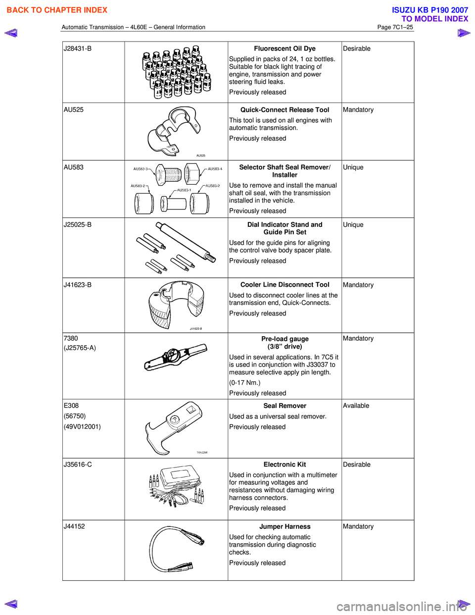
Automatic Transmission – 4L60E – General Information Page 7C1–25
J28431-B
Fluorescent Oil Dye
Supplied in packs of 24, 1 oz bottles.
Suitable for black light tracing of
engine, transmission and power
steering fluid leaks.
Previously released Desirable
AU525
AU525 Quick-Connect Release Tool
This tool is used on all engines with
automatic transmission.
Previously released Mandatory
AU583 Selector Shaft Seal Remover/
Installer
Use to remove and install the manual
shaft oil seal, with the transmission
installed in the vehicle.
Previously released Unique
J25025-B
Dial Indicator Stand and
Guide Pin Set
Used for the guide pins for aligning
the control valve body spacer plate.
Previously released Unique
J41623-B
Cooler Line Disconnect Tool
Used to disconnect cooler lines at the
transmission end, Quick-Connects.
Previously released Mandatory
7380
(J25765-A)
Pre-load gauge
(3/8” drive)
Used in several applications. In 7C5 it
is used in conjunction with J33037 to
measure selective apply pin length.
(0-17 Nm.)
Previously released Mandatory
E308
(56750)
(49V012001)
Seal Remover
Used as a universal seal remover .
Previously released Available
J35616-C
Electronic Kit
Used in conjunction with a multimeter
for measuring voltages and
resistances without damaging wiring
harness connectors.
Previously released Desirable
J44152
Jumper Harness
Used for checking automatic
transmission during diagnostic
checks.
Previously released Mandatory
BACK TO CHAPTER INDEX
TO MODEL INDEX
ISUZU KB P190 2007
Page 3788 of 6020
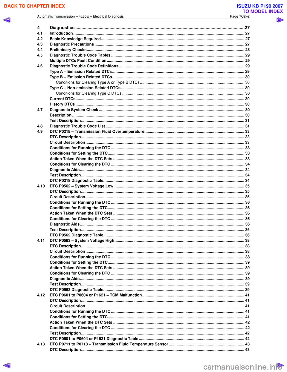
Automatic Transmission – 4L60E – Electrical Diagnosis Page 7C2–2
4 Diagnostics ...........................................................................................................................................27
4.1 Introduction ................................................................................................................... ....................................... 27
4.2 Basic Knowledge Required ....................................................................................................... .......................... 27
4.3 Diagnostic Precautions ....................................................................................................................................... 27
4.4 Preliminary Checks.............................................................................................................................................. 28
4.5 Diagnostic Trouble Code Tables ................................................................................................. ....................... 29
Multiple DTCs Fault Condition ............................................................................................................................ 29
4.6 Diagnostic Trouble Code Definitions ............................................................................................ ..................... 29
Type A – Emission Related DTCs ....................................................................................................................... 29
Type B – Emission Related DTCs ....................................................................................................................... 30
Conditions for Clearing Type A or Type B DTCs .................................................................................. ............ 30
Type C – Non-emission Related DTCs ............................................................................................................... 30
Conditions for Clearing Type C DTCs .............................................................................................................. 30
Current DTCs........................................................................................................................................................ 30
History DTCs ........................................................................................................................................................ 30
4.7 Diagnostic System Check ........................................................................................................ ........................... 30
Description ........................................................................................................................................................... 30
Test Description ................................................................................................................................................... 31
4.8 Diagnostic Trouble Code List ................................................................................................... .......................... 31
4.9 DTC P0218 – Transmission Fluid Overtemperature................................................................................. ......... 33
DTC Description ................................................................................................................................................... 33
Circuit Description ............................................................................................................................................... 33
Conditions for Running the DTC ................................................................................................. ....................... 33
Conditions for Setting the DTC........................................................................................................................... 33
Action Taken When the DTC Sets ................................................................................................. ..................... 33
Conditions for Clearing the DTC ........................................................................................................................ 34
Diagnostic Aids .................................................................................................................................................... 34
Test Description ................................................................................................................................................... 34
DTC P0218 Diagnostic Table..................................................................................................... .......................... 34
4.10 DTC P0562 – System Voltage Low ................................................................................................. .................... 35
DTC Description ................................................................................................................................................... 35
Circuit Description ............................................................................................................................................... 35
Conditions for Running the DTC ................................................................................................. ....................... 36
Conditions for Setting the DTC........................................................................................................................... 36
Action Taken When the DTC Sets ................................................................................................. ..................... 36
Conditions for Clearing the DTC ........................................................................................................................ 36
Diagnostic Aids .................................................................................................................................................... 36
Test Description ................................................................................................................................................... 36
DTC P0562 Diagnostic Table..................................................................................................... .......................... 36
4.11 DTC P0563 – System Voltage High................................................................................................ ..................... 38
DTC Description ................................................................................................................................................... 38
Circuit Description ............................................................................................................................................... 38
Conditions for Running the DTC ................................................................................................. ....................... 38
Conditions for Setting the DTC........................................................................................................................... 39
Action Taken When the DTC Sets ................................................................................................. ..................... 39
Conditions for Clearing the DTC ........................................................................................................................ 39
Diagnostic Aids .................................................................................................................................................... 39
Test Description ................................................................................................................................................... 39
DTC P0563 Diagnostic Table..................................................................................................... .......................... 39
4.12 DTC P0601 to P0604 or P1621 – TCM Malfunction .................................................................................. .......... 41
DTC Description ................................................................................................................................................... 41
Circuit Description ............................................................................................................................................... 41
Conditions for Running the DTC ................................................................................................. ....................... 41
Conditions for Setting the DTC........................................................................................................................... 41
Action Taken When the DTC Sets ................................................................................................. ..................... 42
Conditions for Clearing the DTC ........................................................................................................................ 42
Test Description ................................................................................................................................................... 42
DTC P0601 to P0604 or P1621 Diagnostic Table ................................................................................... ............ 42
4.13 DTC P0711 to P0713 – Transmission Fluid Temperature Sensor .................................................................... 4 3
DTC Description ................................................................................................................................................... 43
BACK TO CHAPTER INDEX
TO MODEL INDEX
ISUZU KB P190 2007
Page 3817 of 6020

Automatic Transmission – 4L60E – Electrical Diagnosis Page 7C2–31
Test Description
The following numbers refer to the step numbers in the diagnostic table:
1 Within this document there are a number of requirements that must be met before you can start diagnosis. Refer to 4.2 Basic Knowledge Required, 4.3 Diagnostic Precautions and 4.4 Preliminary Checks.
2 Checks if there is data communication between Tech 2 and the TCM.
3 Checks if the TCM has set any DTCs. If no DTCs have set, the functional test must be performed, which diagnoses the hydro-mechanical functions of the transmission.
Step Action Yes No
1 Have you read the Basic Diagnostic Requirements, Diagnostic
Precautions and Preliminary Checks? Go to Step 3 Refer to Note 1
2
1 Connect Tech 2 to the DLC.
2 On Tech 2 select: Transmission / Automatic Transmission
and follow the instruction on Tech 2.
Does Tech 2 display the TCM specifications? Go to Step 4 Refer to 6E1
Powertrain Interface
Module
3 On Tech 2 select:
Diagnostic Trouble Codes / Read DTC Information
Does Tech 2 display any DTCs?
Go to
4.8 Diagnostic Trouble Code List Perform the
Functional Test, refer to 7C3 Automatic
Transmission –
4L60E – Hydraulic and Mechanical Diagnosis
4.8 Diagnostic Trouble Code List
NOTE
If the DTC listed on Tech 2 is not contained in
this list, refer to OD Vehicle Diagnostics.
DTC Type Description Diagnostic Table
P0218 C Transmission Fluid Overtemperature 4.9 DTC P0218 – Transmission
Fluid Overtemperature
P0562 C System Voltage Low 4.10 DTC P0562 – System
Voltage Low
P0563 C System Voltage High 4.11 DTC P0563 – System
Voltage High
P0601 A Transmission Control Module (TCM) Read Only Memory
(ROM) 4.12 DTC P0601 to P0604 or
P1621 – TCM Malfunction
P0602 A Transmission Control Module (TCM) Not Programmed 4.12 DTC P0601 to P0604 or
P1621 – TCM Malfunction
P0603 A Transmission Control Module (TCM) Random Access
Memory (RAM) 4.12 DTC P0601 to P0604 or
P1621 – TCM Malfunction
P0604 A Transmission Control Module (TCM) Long Term Memory
Performance 4.12 DTC P0601 to P0604 or
P1621 – TCM Malfunction
P0711 C Transmission Fluid Temperature (TFT) Sensor
Performance 4.13 DTC P0711 to P0713 –
Transmission Fluid Temperature
Sensor
P0712 C Transmission Fluid Temperature (TFT) Sensor Circuit Low
Voltage 4.13 DTC P0711 to P0713 –
Transmission Fluid Temperature
Sensor
BACK TO CHAPTER INDEX
TO MODEL INDEX
ISUZU KB P190 2007
Page 3820 of 6020
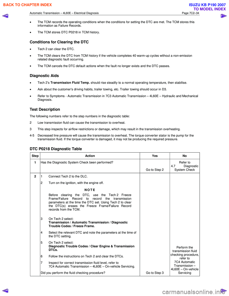
Automatic Transmission – 4L60E – Electrical Diagnosis Page 7C2–34
• The TCM records the operating conditions when the conditions for setting the DTC are met. The TCM stores this
information as Failure Records.
• The TCM stores DTC P0218 in TCM history.
Conditions for Clearing the DTC
• Tech 2 can clear the DTC.
• The TCM clears the DTC from TCM history if the vehicle completes 40 warm-up cycles without a non-emission
related diagnostic fault occurring.
• The TCM cancels the DTC default actions when the fault no longer exists and the DTC passes.
Diagnostic Aids
• Tech 2’s Transmission Fluid Temp. should rise steadily to a normal operating temperature, then stabilise.
• Ask about the customer's driving habits, trailer towing, etc. Trailer towing should occur in D3.
• Refer to Symptoms - Automatic Transmission in 7C3 Automatic Transmission – 4L60E – Hydraulic and Mechanical
Diagnosis.
Test Description
The following numbers refer to the step numbers in the diagnostic table:
2 Low transmission fluid can cause the transmission to overheat.
3 This step inspects for airflow restrictions or damage, which may result in the transmission overheating.
4-5 Decreased line pressure will cause the transmission to overheat. The torque converter stator is the pump for the transmission fluid. If the torque converter is damaged, it may not be producing the required pressure.
DTC P0218 Diagnostic Table
Step Action Yes No
1 Has the Diagnostic System Check been performed?
Go to Step 2 Refer to
4.7 Diagnostic System Check
2 1 Connect Tech 2 to the DLC.
2 Turn on the ignition, with the engine off.
NOTE
Before clearing the DTC, use the Tech 2 Freeze
Frame/Failure Record to record the transmission
parameters at the time the DTC set. Using Tech 2 to clear
the DTC(s) erases the Freeze Frame/Failure Record
records from the TCM.
3 On Tech 2 select: Transmission / Automatic Transmission / Diagnostic
Trouble Codes / Freeze Frame.
4 Select the relevant DTC and note the parameters at the time of the DTC setting.
5 On Tech 2 select:
Diagnostic Trouble Codes / Clear Engine & Transmission
DTCs.
6 Follow the instructions on Tech 2 and clear the DTCs.
7 Inspect for correct transmission fluid level, refer to 7C4 Automatic Transmission – 4L60E – On-vehicle Servicing.
Did you perform the fluid checking procedure? Go to Step 3 Perform the
transmission fluid
checking procedure, refer to
7C4 Automatic
Transmission –
4L60E – On-vehicle Servicing
BACK TO CHAPTER INDEX
TO MODEL INDEX
ISUZU KB P190 2007