2007 ISUZU KB P190 brake light
[x] Cancel search: brake lightPage 640 of 6020

BRAKE CONTROL SYSTEM 5A-47
ABS Warning Lamp ON Steady
Step Action Value(s) Yes No
1 1. Check the ABS warning lamp lighting circuit for a
short.
2. If a problem found, repair as necessary. W as a problem found? - Go to Step 3 Go to Step 2
2 1. Check the ABS warning lamp lighting circuit at the
meter for a short. Refer to METER, W ARNING
LIGHT AND INDICATOR LIGHT in 8 section.
2. If a problem is found, repair or replace the meter. W as a problem found? - Go to Step 3 Go to Step 4
3 1. Connect all connectors.
2. Ignition “ON”, engine “OFF”.
3. W ait for about 10 seconds.
4. Observe the ABS warning lamp. Is the ABS warning lamp turned “OFF”? - Verify repair Go to Step 4
4 Replace EHCU.
Note: Check the EHCU type for specification, the
EHCU is replaced.
(Specification; 2W D or 4W D Model)
Is the action complete? - Verify repair -
BACK TO CHAPTER INDEX
TO MODEL INDEX
ISUZU KB P190 2007
Page 771 of 6020

PARKING BRAKE SYSTEM 5D-1
Service Precaution
Service Precaution
WARNING: THIS VEHICLE HAS A SUPPLEMENTAL
RESTRAINT SYSTEM (SRS). REFER TO THE SRS
COMPONENT AND WIRING LOCATION VIEW IN
ORDER TO DETERMINE WHETHER YOU ARE
PERFORMING SERVICE ON OR NEAR THE SRS
COMPONENTS OR THE SRS WIRING. WHEN YOU
ARE PERFORMING SERVICE ON OR NEAR THE
SRS COMPONENTS OR THE SRS WIRING, REFER
TO THE SRS SERVICE INFORMATION. FAILURE TO
FOLLOW WARNINGS COULD RESULT IN
POSSIBLE AIR BAG DEPLOYMENT, PERSONAL
INJURY, OR OTHERWISE UNNECESSARY SRS
SYSTEM REPAIRS.
CAUTION: Always use the correct fastener in the
proper location. When you replace a fastener, use
ONLY the exact part number for that application.
ISUZU/GM will call out those fasteners that require
a replacement after removal. ISUZU/GM will also
call out the fasteners that require thread lockers o
r
thread sealant. UNLESS OTHERWISE SPECIFIED,
do not use supplemental coatings (paints, greases,
or other corrosion inhibitors) on threaded fasteners
or fastener joint interfaces. Generally, such
coatings adversely affect the fastener torque and
the joint clamping force, and may damage the
fastener. When you install fasteners, use the
correct tightening sequence and specifications.
Following these instructions can help you avoid
damage to parts and systems.
General Description
Pulling up the parking brake lever by hand will set the
parking brake. By means of a ratchet type lock, the
lever can be held in that position until it is released. The
position of the lever is transmitted through cable/leve
r
systems to the rear wheels. These parts are designed
to obtain sufficient braking force even when parking on
slopes. W hen the parking brake is set, or when the
ignition SW is in the “ON” position, the brake warning
light illuminates. The rear wheel parking brake is a
leading-trailing brake (mechanical inside expansion
type) built in the rear drum brake. Parking brake
adjustment is made through the adjusting hole (bored
through back plate). Parking brake lever stroke should
be adjusted to 8 −14 notches with 294N (30 kg / 66 lb)
(bench seat) or 6 −9 notches with 294N (30 kg / 66 lb)
(bucket seat). Refer to “Parking Brake Adjustment” in
this section.
BACK TO CHAPTER INDEX
TO MODEL INDEX
ISUZU KB P190 2007
Page 1138 of 6020
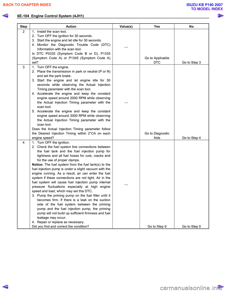
6E-104 Engine Control System (4JH1)
Step Action Value(s) Yes No
2 1. Install the scan tool.
2. Turn OFF the ignition for 30 seconds.
3. Start the engine and let idle for 30 seconds.
4. Monitor the Diagnostic Trouble Code (DTC) Information with the scan tool.
Is DTC P0335 (Symptom Code B or D), P1335
(Symptom Code A) or P1345 (Symptom Code A)
set?
Go to Applicable DTC Go to Step 3
3 1. Turn OFF the engine. 2. Place the transmission in park or neutral (P or N) and set the park brake.
3. Start the engine and let engine idle for 30 seconds while observing the Actual Injection
Timing parameter with the scan tool.
4. Accelerate the engine and keep the constant engine speed around 2000 RPM while observing
the Actual Injection Timing parameter with the
scan tool.
5. Accelerate the engine and keep the constant engine speed around 3000 RPM while observing
the Actual Injection Timing parameter with the
scan tool.
Does the Actual Injection Timing parameter follow
the Desired Injection Timing within 2°CA on each
engine speed?
Go to Diagnostic Aids Go to Step 4
4 1. Turn OFF the ignition. 2. Check the fuel system line connections between the fuel tank and the fuel injection pump for
tightness and all fuel hoses for cuts, cracks and
for the use of proper clamps.
Notice: The fuel system from the fuel tank(s) to the
fuel injection pump is under a slight vacuum with the
engine running. As a result, air can enter the fuel
system if these connections are not tight. Air in the
fuel system will cause fuel injection pump internal
pressure fluctuations especially at high engine
speed and load, which may set this DTC.
3. Pump the priming pump on the fuel filter until it becomes firm. If there is a leak on the suction
side of the fuel system between the priming
pump and the fuel injection pump, the priming
pump will not build up sufficient firmness and fuel
leakage may occur.
4. Repair or replace as necessary.
Did you find and correct the condition?
Go to Step 9 Go to Step 5
BACK TO CHAPTER INDEX
TO MODEL INDEX
ISUZU KB P190 2007
Page 1215 of 6020
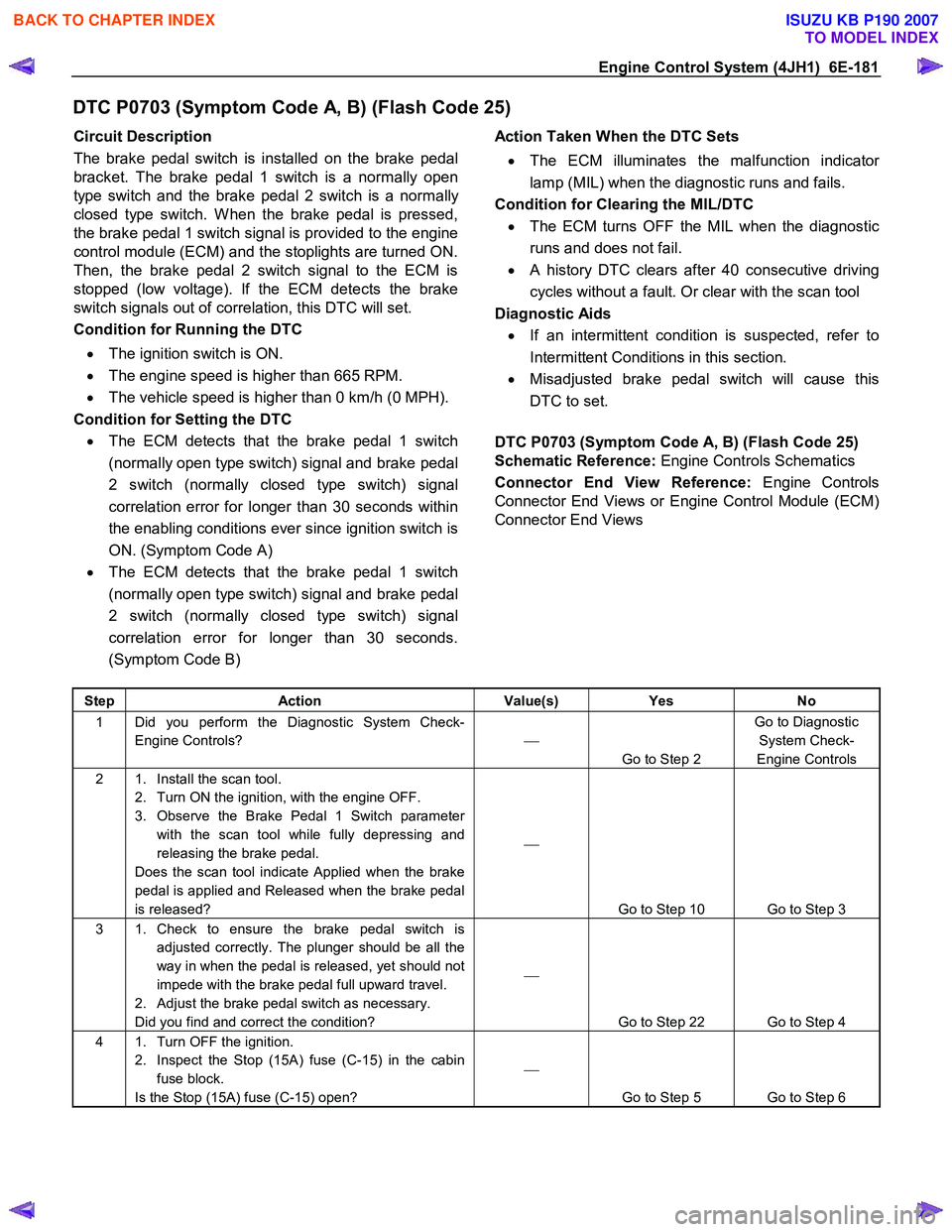
Engine Control System (4JH1) 6E-181
DTC P0703 (Symptom Code A, B) (Flash Code 25)
Circuit Description
The brake pedal switch is installed on the brake pedal
bracket. The brake pedal 1 switch is a normally open
type switch and the brake pedal 2 switch is a normally
closed type switch. W hen the brake pedal is pressed,
the brake pedal 1 switch signal is provided to the engine
control module (ECM) and the stoplights are turned ON.
Then, the brake pedal 2 switch signal to the ECM is
stopped (low voltage). If the ECM detects the brake
switch signals out of correlation, this DTC will set.
Condition for Running the DTC
• The ignition switch is ON.
• The engine speed is higher than 665 RPM.
• The vehicle speed is higher than 0 km/h (0 MPH).
Condition for Setting the DTC • The ECM detects that the brake pedal 1 switch
(normally open type switch) signal and brake pedal
2 switch (normally closed type switch) signal
correlation error for longer than 30 seconds within
the enabling conditions ever since ignition switch is
ON. (Symptom Code A)
• The ECM detects that the brake pedal 1 switch
(normally open type switch) signal and brake pedal
2 switch (normally closed type switch) signal
correlation error for longer than 30 seconds.
(Symptom Code B)
Action Taken When the DTC Sets
• The ECM illuminates the malfunction indicato
r
lamp (MIL) when the diagnostic runs and fails.
Condition for Clearing the MIL/DTC • The ECM turns OFF the MIL when the diagnostic
runs and does not fail.
• A history DTC clears after 40 consecutive driving
cycles without a fault. Or clear with the scan tool
Diagnostic Aids • If an intermittent condition is suspected, refer to
Intermittent Conditions in this section.
• Misadjusted brake pedal switch will cause this
DTC to set.
DTC P0703 (Symptom Code A, B) (Flash Code 25)
Schematic Reference: Engine Controls Schematics
Connector End View Reference: Engine Controls
Connector End Views or Engine Control Module (ECM)
Connector End Views
Step Action Value(s) Yes No
1 Did you perform the Diagnostic System Check-
Engine Controls?
Go to Step 2 Go to Diagnostic
System Check-
Engine Controls
2 1. Install the scan tool. 2. Turn ON the ignition, with the engine OFF.
3. Observe the Brake Pedal 1 Switch parameter with the scan tool while fully depressing and
releasing the brake pedal.
Does the scan tool indicate Applied when the brake
pedal is applied and Released when the brake pedal
is released?
Go to Step 10 Go to Step 3
3 1. Check to ensure the brake pedal switch is adjusted correctly. The plunger should be all the
way in when the pedal is released, yet should not
impede with the brake pedal full upward travel.
2. Adjust the brake pedal switch as necessary.
Did you find and correct the condition?
Go to Step 22 Go to Step 4
4 1. Turn OFF the ignition. 2. Inspect the Stop (15A) fuse (C-15) in the cabin fuse block.
Is the Stop (15A) fuse (C-15) open?
Go to Step 5 Go to Step 6
BACK TO CHAPTER INDEX
TO MODEL INDEX
ISUZU KB P190 2007
Page 1231 of 6020
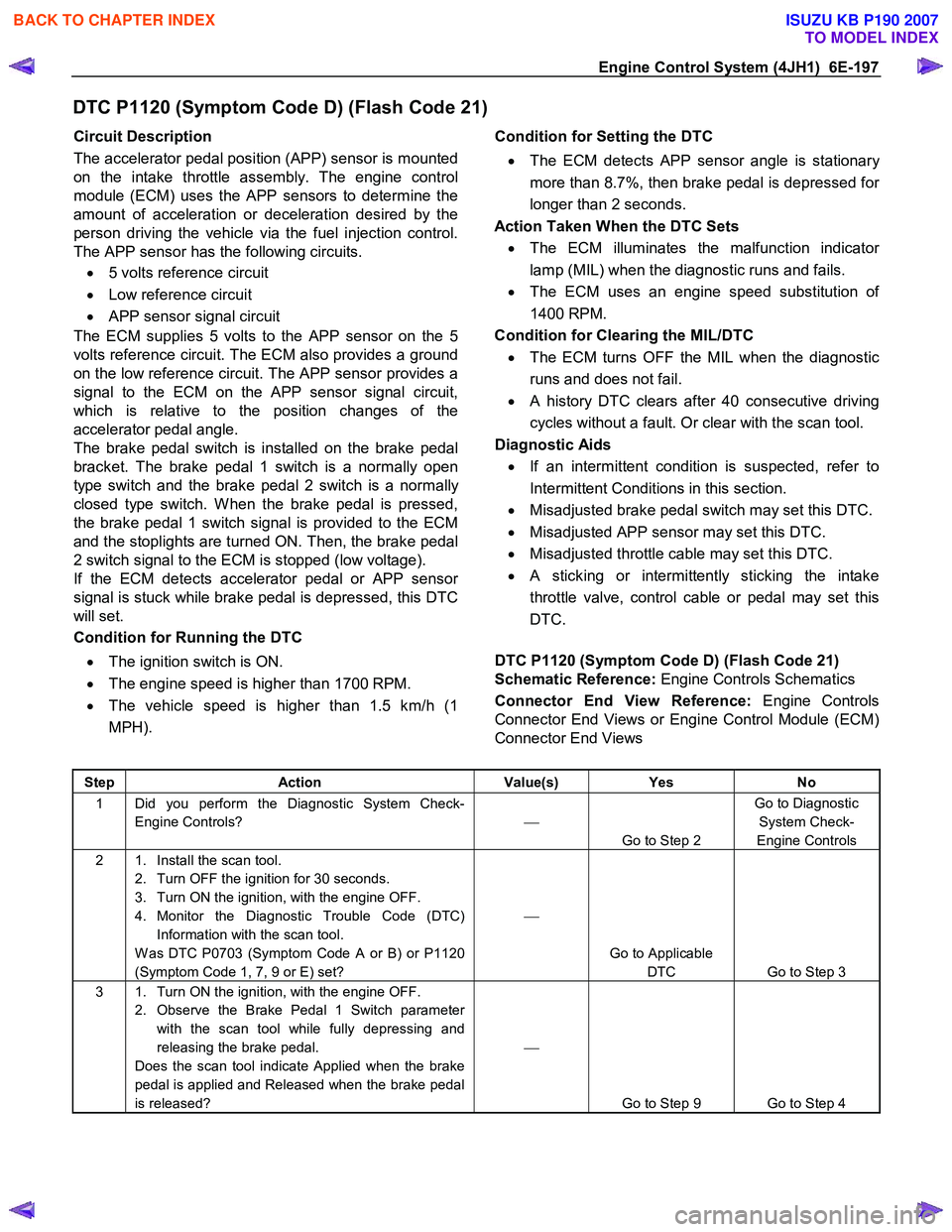
Engine Control System (4JH1) 6E-197
DTC P1120 (Symptom Code D) (Flash Code 21)
Circuit Description
The accelerator pedal position (APP) sensor is mounted
on the intake throttle assembly. The engine control
module (ECM) uses the APP sensors to determine the
amount of acceleration or deceleration desired by the
person driving the vehicle via the fuel injection control.
The APP sensor has the following circuits.
• 5 volts reference circuit
• Low reference circuit
• APP sensor signal circuit
The ECM supplies 5 volts to the APP sensor on the 5
volts reference circuit. The ECM also provides a ground
on the low reference circuit. The APP sensor provides a
signal to the ECM on the APP sensor signal circuit,
which is relative to the position changes of the
accelerator pedal angle.
The brake pedal switch is installed on the brake pedal
bracket. The brake pedal 1 switch is a normally open
type switch and the brake pedal 2 switch is a normally
closed type switch. W hen the brake pedal is pressed,
the brake pedal 1 switch signal is provided to the ECM
and the stoplights are turned ON. Then, the brake pedal
2 switch signal to the ECM is stopped (low voltage).
If the ECM detects accelerator pedal or APP senso
r
signal is stuck while brake pedal is depressed, this DTC
will set.
Condition for Running the DTC
• The ignition switch is ON.
• The engine speed is higher than 1700 RPM.
• The vehicle speed is higher than 1.5 km/h (1
MPH).
Condition for Setting the DTC
• The ECM detects APP sensor angle is stationar
y
more than 8.7%, then brake pedal is depressed fo
r
longer than 2 seconds.
Action Taken When the DTC Sets • The ECM illuminates the malfunction indicato
r
lamp (MIL) when the diagnostic runs and fails.
• The ECM uses an engine speed substitution o
f
1400 RPM.
Condition for Clearing the MIL/DTC • The ECM turns OFF the MIL when the diagnostic
runs and does not fail.
• A history DTC clears after 40 consecutive driving
cycles without a fault. Or clear with the scan tool.
Diagnostic Aids • If an intermittent condition is suspected, refer to
Intermittent Conditions in this section.
• Misadjusted brake pedal switch may set this DTC.
• Misadjusted APP sensor may set this DTC.
• Misadjusted throttle cable may set this DTC.
• A sticking or intermittently sticking the intake
throttle valve, control cable or pedal may set this
DTC.
DTC P1120 (Symptom Code D) (Flash Code 21)
Schematic Reference: Engine Controls Schematics
Connector End View Reference: Engine Controls
Connector End Views or Engine Control Module (ECM)
Connector End Views
Step Action Value(s) Yes No
1 Did you perform the Diagnostic System Check-
Engine Controls?
Go to Step 2 Go to Diagnostic
System Check-
Engine Controls
2 1. Install the scan tool. 2. Turn OFF the ignition for 30 seconds.
3. Turn ON the ignition, with the engine OFF.
4. Monitor the Diagnostic Trouble Code (DTC) Information with the scan tool.
W as DTC P0703 (Symptom Code A or B) or P1120
(Symptom Code 1, 7, 9 or E) set?
Go to Applicable DTC Go to Step 3
3 1. Turn ON the ignition, with the engine OFF. 2. Observe the Brake Pedal 1 Switch parameter with the scan tool while fully depressing and
releasing the brake pedal.
Does the scan tool indicate Applied when the brake
pedal is applied and Released when the brake pedal
is released?
Go to Step 9 Go to Step 4
BACK TO CHAPTER INDEX
TO MODEL INDEX
ISUZU KB P190 2007
Page 1377 of 6020
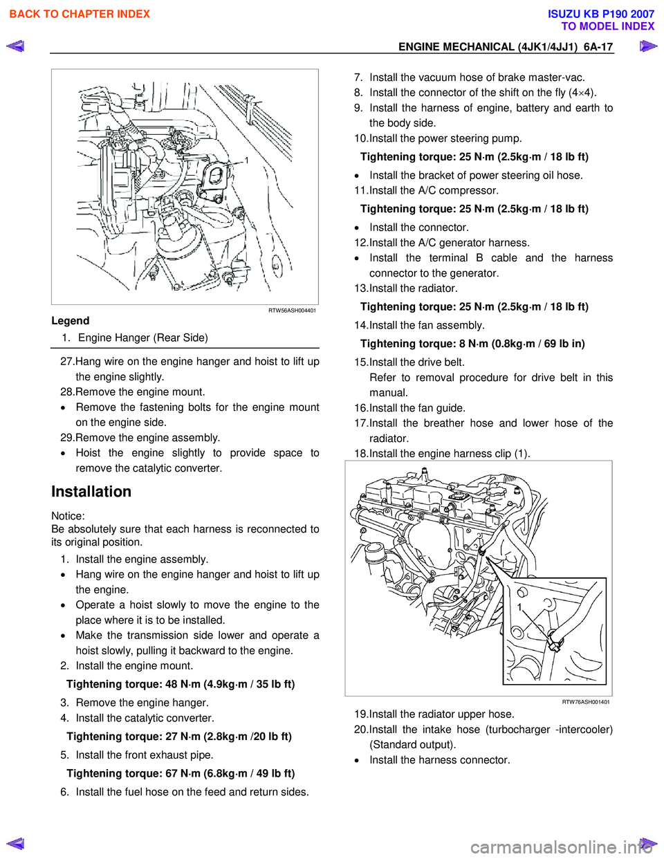
ENGINE MECHANICAL (4JK1/4JJ1) 6A-17
RTW 56ASH004401
Legend
1. Engine Hanger (Rear Side)
27.Hang wire on the engine hanger and hoist to lift up
the engine slightly.
28.Remove the engine mount.
• Remove the fastening bolts for the engine mount
on the engine side.
29.Remove the engine assembly.
• Hoist the engine slightly to provide space to
remove the catalytic converter.
Installation
Notice:
Be absolutely sure that each harness is reconnected to
its original position.
1. Install the engine assembly.
• Hang wire on the engine hanger and hoist to lift up
the engine.
• Operate a hoist slowly to move the engine to the
place where it is to be installed.
• Make the transmission side lower and operate a
hoist slowly, pulling it backward to the engine.
2. Install the engine mount.
Tightening torque: 48 N ⋅
⋅⋅
⋅
m (4.9kg ⋅
⋅⋅
⋅
m / 35 lb ft)
3. Remove the engine hanger.
4. Install the catalytic converter.
Tightening torque: 27 N ⋅
⋅⋅
⋅
m (2.8kg ⋅
⋅⋅
⋅
m /20 lb ft)
5. Install the front exhaust pipe. Tightening torque: 67 N ⋅
⋅⋅
⋅
m (6.8kg ⋅
⋅⋅
⋅
m / 49 lb ft)
6. Install the fuel hose on the feed and return sides.
7. Install the vacuum hose of brake master-vac.
8. Install the connector of the shift on the fly (4 ×4).
9. Install the harness of engine, battery and earth to the body side.
10.Install the power steering pump.
Tightening torque: 25 N ⋅
⋅⋅
⋅
m (2.5kg ⋅
⋅⋅
⋅
m / 18 lb ft)
• Install the bracket of power steering oil hose.
11.Install the A/C compressor.
Tightening torque: 25 N ⋅
⋅⋅
⋅
m (2.5kg ⋅
⋅⋅
⋅
m / 18 lb ft)
• Install the connector.
12.Install the A/C generator harness.
• Install the terminal B cable and the harness
connector to the generator.
13.Install the radiator.
Tightening torque: 25 N ⋅
⋅⋅
⋅
m (2.5kg ⋅
⋅⋅
⋅
m / 18 lb ft)
14.Install the fan assembly. Tightening torque: 8 N ⋅
⋅⋅
⋅
m (0.8kg ⋅
⋅⋅
⋅
m / 69 lb in)
15.Install the drive belt.
Refer to removal procedure for drive belt in this manual.
16.Install the fan guide.
17.Install the breather hose and lower hose of the radiator.
18.Install the engine harness clip (1).
RTW 76ASH001401
19.Install the radiator upper hose.
20.Install the intake hose (turbocharger -intercooler) (Standard output).
• Install the harness connector.
BACK TO CHAPTER INDEX
TO MODEL INDEX
ISUZU KB P190 2007
Page 1808 of 6020
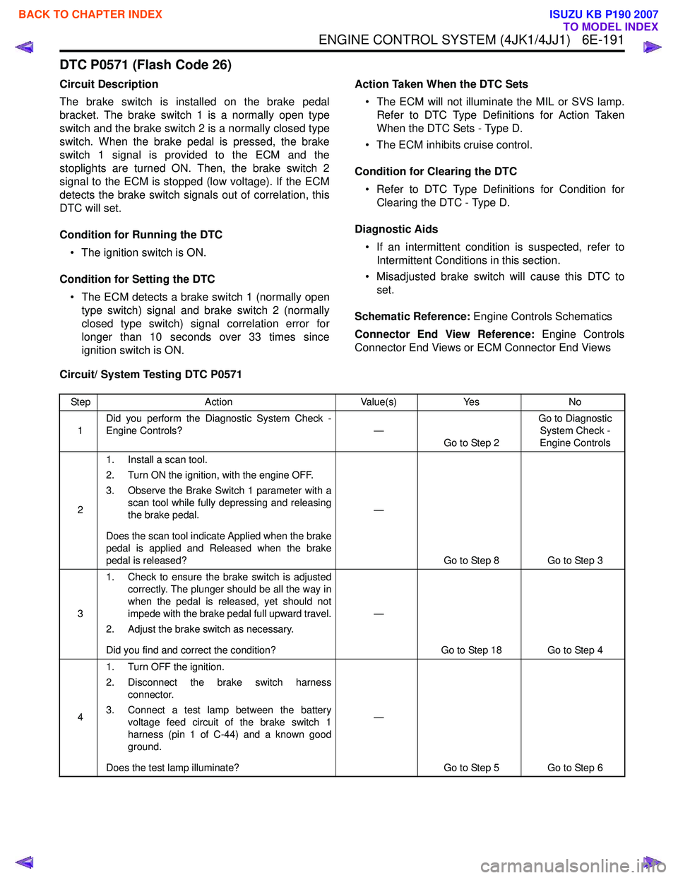
ENGINE CONTROL SYSTEM (4JK1/4JJ1) 6E-191
DTC P0571 (Flash Code 26)
Circuit Description
The brake switch is installed on the brake pedal
bracket. The brake switch 1 is a normally open type
switch and the brake switch 2 is a normally closed type
switch. When the brake pedal is pressed, the brake
switch 1 signal is provided to the ECM and the
stoplights are turned ON. Then, the brake switch 2
signal to the ECM is stopped (low voltage). If the ECM
detects the brake switch signals out of correlation, this
DTC will set.
Condition for Running the DTC • The ignition switch is ON.
Condition for Setting the DTC • The ECM detects a brake switch 1 (normally open type switch) signal and brake switch 2 (normally
closed type switch) signal correlation error for
longer than 10 seconds over 33 times since
ignition switch is ON. Action Taken When the DTC Sets
• The ECM will not illuminate the MIL or SVS lamp. Refer to DTC Type Definitions for Action Taken
When the DTC Sets - Type D.
• The ECM inhibits cruise control.
Condition for Clearing the DTC • Refer to DTC Type Definitions for Condition for Clearing the DTC - Type D.
Diagnostic Aids • If an intermittent condition is suspected, refer to Intermittent Conditions in this section.
• Misadjusted brake switch will cause this DTC to set.
Schematic Reference: Engine Controls Schematics
Connector End View Reference: Engine Controls
Connector End Views or ECM Connector End Views
Circuit/ System Testing DTC P0571
Step Action Value(s)Yes No
1 Did you perform the Diagnostic System Check -
Engine Controls? —
Go to Step 2 Go to Diagnostic
System Check -
Engine Controls
2 1. Install a scan tool.
2. Turn ON the ignition, with the engine OFF.
3. Observe the Brake Switch 1 parameter with a scan tool while fully depressing and releasing
the brake pedal.
Does the scan tool indicate Applied when the brake
pedal is applied and Released when the brake
pedal is released? —
Go to Step 8 Go to Step 3
3 1. Check to ensure the brake switch is adjusted
correctly. The plunger should be all the way in
when the pedal is released, yet should not
impede with the brake pedal full upward travel.
2. Adjust the brake switch as necessary.
Did you find and correct the condition? —
Go to Step 18 Go to Step 4
4 1. Turn OFF the ignition.
2. Disconnect the brake switch harness connector.
3. Connect a test lamp between the battery voltage feed circuit of the brake switch 1
harness (pin 1 of C-44) and a known good
ground.
Does the test lamp illuminate? —
Go to Step 5 Go to Step 6
BACK TO CHAPTER INDEX
TO MODEL INDEX
ISUZU KB P190 2007
Page 1809 of 6020
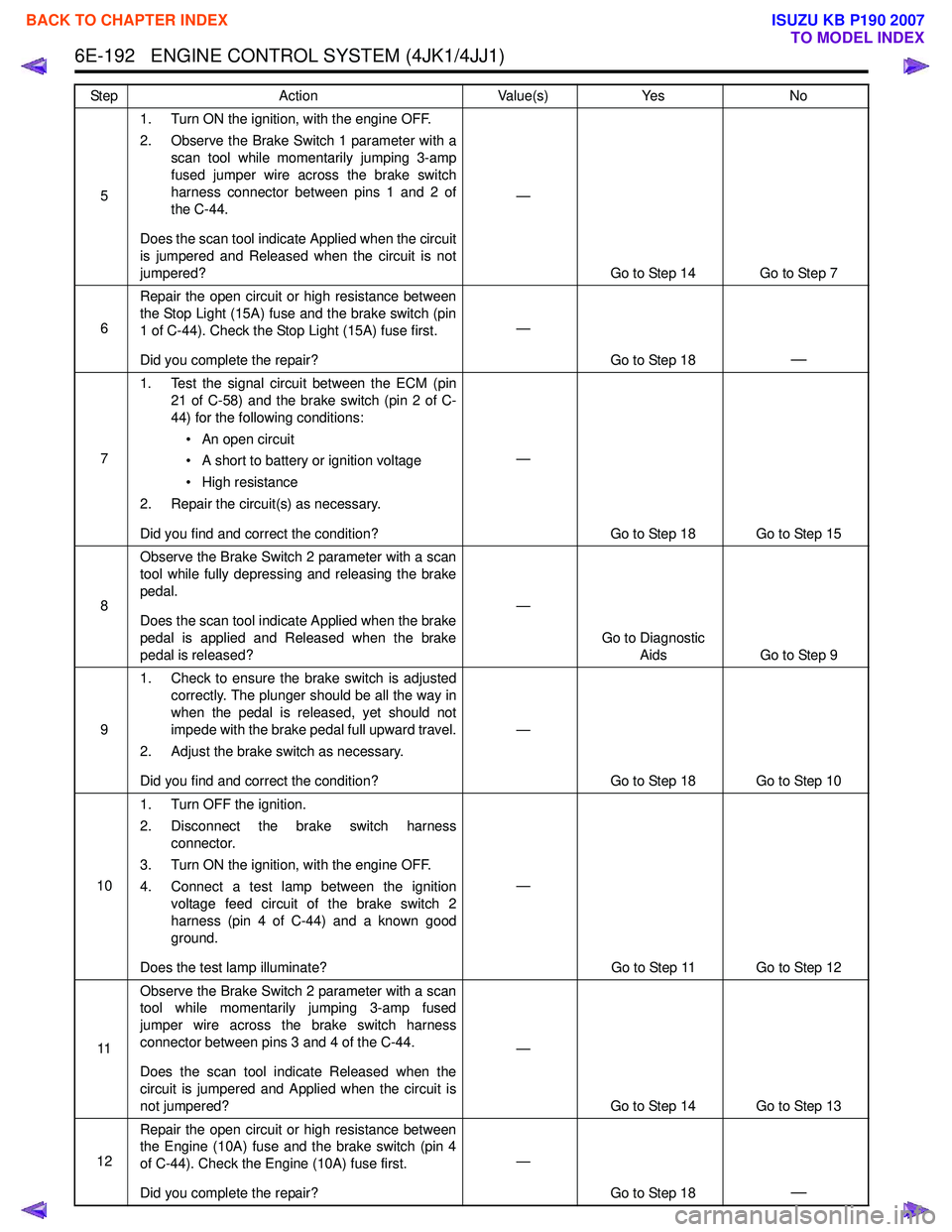
6E-192 ENGINE CONTROL SYSTEM (4JK1/4JJ1)
51. Turn ON the ignition, with the engine OFF.
2. Observe the Brake Switch 1 parameter with a scan tool while momentarily jumping 3-amp
fused jumper wire across the brake switch
harness connector between pins 1 and 2 of
the C-44.
Does the scan tool indicate Applied when the circuit
is jumpered and Released when the circuit is not
jumpered? —
Go to Step 14 Go to Step 7
6 Repair the open circuit or high resistance between
the Stop Light (15A) fuse and the brake switch (pin
1 of C-44). Check the Stop Light (15A) fuse first.
Did you complete the repair? —
Go to Step 18
—
71. Test the signal circuit between the ECM (pin
21 of C-58) and the brake switch (pin 2 of C-
44) for the following conditions:
• An open circuit
• A short to battery or ignition voltage
• High resistance
2. Repair the circuit(s) as necessary.
Did you find and correct the condition? —
Go to Step 18 Go to Step 15
8 Observe the Brake Switch 2 parameter with a scan
tool while fully depressing and releasing the brake
pedal.
Does the scan tool indicate Applied when the brake
pedal is applied and Released when the brake
pedal is released? —
Go to Diagnostic Aids Go to Step 9
9 1. Check to ensure the brake switch is adjusted
correctly. The plunger should be all the way in
when the pedal is released, yet should not
impede with the brake pedal full upward travel.
2. Adjust the brake switch as necessary.
Did you find and correct the condition? —
Go to Step 18 Go to Step 10
10 1. Turn OFF the ignition.
2. Disconnect the brake switch harness connector.
3. Turn ON the ignition, with the engine OFF.
4. Connect a test lamp between the ignition voltage feed circuit of the brake switch 2
harness (pin 4 of C-44) and a known good
ground.
Does the test lamp illuminate? —
Go to Step 11 Go to Step 12
11 Observe the Brake Switch 2 parameter with a scan
tool while momentarily jumping 3-amp fused
jumper wire across the brake switch harness
connector between pins 3 and 4 of the C-44.
Does the scan tool indicate Released when the
circuit is jumpered and Applied when the circuit is
not jumpered? —
Go to Step 14 Go to Step 13
12 Repair the open circuit or high resistance between
the Engine (10A) fuse and the brake switch (pin 4
of C-44). Check the Engine (10A) fuse first.
Did you complete the repair? —
Go to Step 18
—
Step Action Value(s)Yes No
BACK TO CHAPTER INDEX
TO MODEL INDEX
ISUZU KB P190 2007