2007 ISUZU KB P190 ignition
[x] Cancel search: ignitionPage 4371 of 6020
TRANSMISSION CONTROL SYSTEM (JR405E) 7A2-87
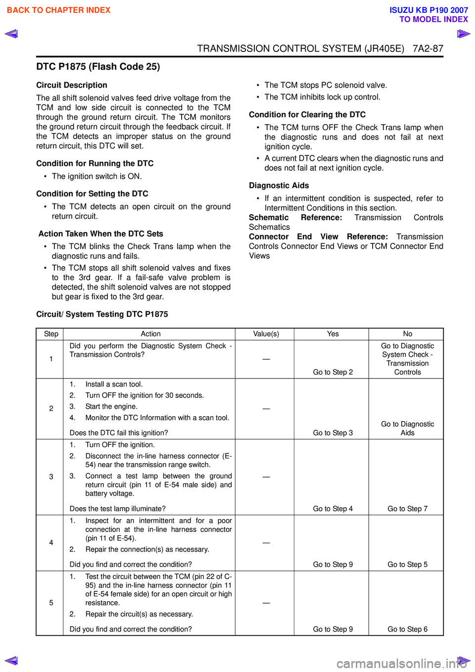
DTC P1875 (Flash Code 25)
Circuit Description
The all shift solenoid valves feed drive voltage from the
TCM and low side circuit is connected to the TCM
through the ground return circuit. The TCM monitors
the ground return circuit through the feedback circuit. If
the TCM detects an improper status on the ground
return circuit, this DTC will set.
Condition for Running the DTC • The ignition switch is ON.
Condition for Setting the DTC • The TCM detects an open circuit on the ground return circuit.
Action Taken When the DTC Sets • The TCM blinks the Check Trans lamp when the diagnostic runs and fails.
• The TCM stops all shift solenoid valves and fixes to the 3rd gear. If a fail-safe valve problem is
detected, the shift solenoid valves are not stopped
but gear is fixed to the 3rd gear. • The TCM stops PC solenoid valve.
• The TCM inhibits lock up control.
Condition for Clearing the DTC • The TCM turns OFF the Check Trans lamp when the diagnostic runs and does not fail at next
ignition cycle.
• A current DTC clears when the diagnostic runs and does not fail at next ignition cycle.
Diagnostic Aids • If an intermittent condition is suspected, refer to Intermittent Conditions in this section.
Schematic Reference: Transmission Controls
Schematics
Connector End View Reference: Transmission
Controls Connector End Views or TCM Connector End
Views
Circuit/ System Testing DTC P1875
Step Action Value(s)Yes No
1 Did you perform the Diagnostic System Check -
Transmission Controls? —
Go to Step 2 Go to Diagnostic
System Check -
Transmission Controls
2 1. Install a scan tool.
2. Turn OFF the ignition for 30 seconds.
3. Start the engine.
4. Monitor the DTC Information with a scan tool.
Does the DTC fail this ignition? —
Go to Step 3 Go to Diagnostic
Aids
3 1. Turn OFF the ignition.
2. Disconnect the in-line harness connector (E- 54) near the transmission range switch.
3. Connect a test lamp between the ground return circuit (pin 11 of E-54 male side) and
battery voltage.
Does the test lamp illuminate? —
Go to Step 4 Go to Step 7
4 1. Inspect for an intermittent and for a poor
connection at the in-line harness connector
(pin 11 of E-54).
2. Repair the connection(s) as necessary.
Did you find and correct the condition? —
Go to Step 9 Go to Step 5
5 1. Test the circuit between the TCM (pin 22 of C-
95) and the in-line harness connector (pin 11
of E-54 female side) for an open circuit or high
resistance.
2. Repair the circuit(s) as necessary.
Did you find and correct the condition? —
Go to Step 9 Go to Step 6
BACK TO CHAPTER INDEX
TO MODEL INDEX
ISUZU KB P190 2007
Page 4372 of 6020

7A2-88 TRANSMISSION CONTROL SYSTEM (JR405E)
61. Turn OFF the ignition.
2. Disconnect the TCM harness connector.
3. Inspect for an intermittent and for a poor connection at the harness connector of the
TCM (pin 22 of C-95).
4. Repair the connection(s) as necessary.
Did you find and correct the condition? —
Go to Step 9 Go to Step 8
7 1. Remove the transmission oil pan. Refer to
repair instructions (On-Vehicle Service).
2. Inspect for an intermittent and for a poor connection at the ground terminal or in-line
harness connector. Clean or tighten grounds
as necessary.
3. Repair the open circuit or high between the ground terminal and the in-line harness
connector (pin 11 of E-54 male side).
Did you complete the repair? —
Go to Step 9 —
8 Important:
Replacement TCM must be
programmed.
Replace the TCM. Refer to TCM Replacement.
Did you complete the replacement? —
Go to Step 9 —
9 1. Reconnect all previously disconnected
components or harness connector(s).
2. Clear the DTCs with a scan tool.
3. Turn OFF the ignition for 30 seconds.
4. Start the engine.
Did the DTC fail this ignition? —
Go to Step 3 Go to Step 10
10 Observe the DTC Information with a scan tool.
Are there any DTCs that you have not diagnosed? —
Go to DTC List System OK
Step
Action Value(s)Yes No
BACK TO CHAPTER INDEX
TO MODEL INDEX
ISUZU KB P190 2007
Page 4373 of 6020
TRANSMISSION CONTROL SYSTEM (JR405E) 7A2-89
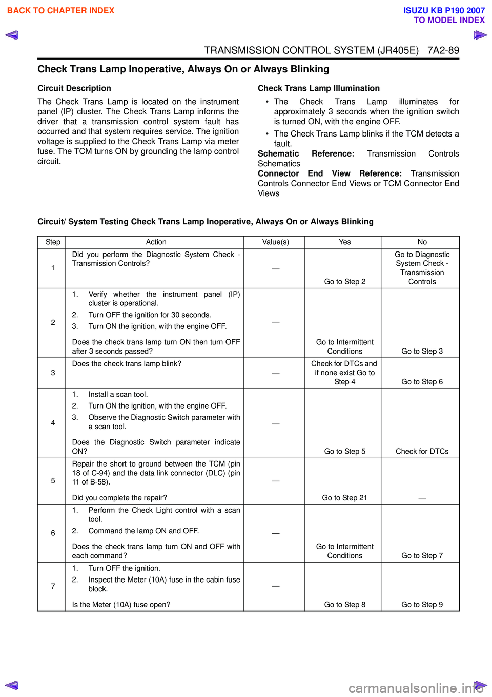
Check Trans Lamp Inoperative, Always On or Always Blinking
Circuit Description
The Check Trans Lamp is located on the instrument
panel (IP) cluster. The Check Trans Lamp informs the
driver that a transmission control system fault has
occurred and that system requires service. The ignition
voltage is supplied to the Check Trans Lamp via meter
fuse. The TCM turns ON by grounding the lamp control
circuit. Check Trans Lamp Illumination
• The Check Trans Lamp illuminates for approximately 3 seconds when the ignition switch
is turned ON, with the engine OFF.
• The Check Trans Lamp blinks if the TCM detects a fault.
Schematic Reference: Transmission Controls
Schematics
Connector End View Reference: Transmission
Controls Connector End Views or TCM Connector End
Views
Circuit/ System Testing Check Trans Lamp Inoperative, Always On or Always Blinking
Step Action Value(s)Yes No
1 Did you perform the Diagnostic System Check -
Transmission Controls? —
Go to Step 2 Go to Diagnostic
System Check -
Transmission Controls
2 1. Verify whether the instrument panel (IP)
cluster is operational.
2. Turn OFF the ignition for 30 seconds.
3. Turn ON the ignition, with the engine OFF.
Does the check trans lamp turn ON then turn OFF
after 3 seconds passed? —
Go to Intermittent Conditions Go to Step 3
3 Does the check trans lamp blink?
—Check for DTCs and
if none exist Go to
Step 4 Go to Step 6
4 1. Install a scan tool.
2. Turn ON the ignition, with the engine OFF.
3. Observe the Diagnostic Switch parameter with a scan tool.
Does the Diagnostic Switch parameter indicate
ON? —
Go to Step 5 Check for DTCs
5 Repair the short to ground between the TCM (pin
18 of C-94) and the data link connector (DLC) (pin
11 o f B - 5 8 ) .
Did you complete the repair? —
Go to Step 21 —
6 1. Perform the Check Light control with a scan
tool.
2. Command the lamp ON and OFF.
Does the check trans lamp turn ON and OFF with
each command? —
Go to Intermittent Conditions Go to Step 7
7 1. Turn OFF the ignition.
2. Inspect the Meter (10A) fuse in the cabin fuse block.
Is the Meter (10A) fuse open? —
Go to Step 8 Go to Step 9
BACK TO CHAPTER INDEX
TO MODEL INDEX
ISUZU KB P190 2007
Page 4374 of 6020
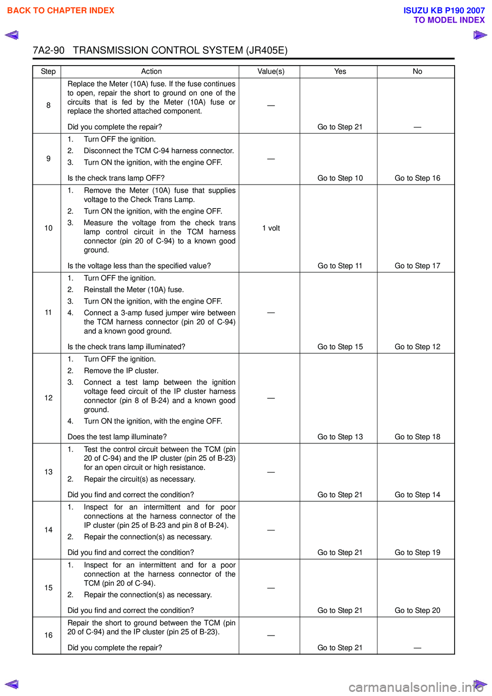
7A2-90 TRANSMISSION CONTROL SYSTEM (JR405E)
8Replace the Meter (10A) fuse. If the fuse continues
to open, repair the short to ground on one of the
circuits that is fed by the Meter (10A) fuse or
replace the shorted attached component.
Did you complete the repair? —
Go to Step 21 —
9 1. Turn OFF the ignition.
2. Disconnect the TCM C-94 harness connector.
3. Turn ON the ignition, with the engine OFF.
Is the check trans lamp OFF? —
Go to Step 10 Go to Step 16
10 1. Remove the Meter (10A) fuse that supplies
voltage to the Check Trans Lamp.
2. Turn ON the ignition, with the engine OFF.
3. Measure the voltage from the check trans lamp control circuit in the TCM harness
connector (pin 20 of C-94) to a known good
ground.
Is the voltage less than the specified value? 1 volt
Go to Step 11 Go to Step 17
11 1. Turn OFF the ignition.
2. Reinstall the Meter (10A) fuse.
3. Turn ON the ignition, with the engine OFF.
4. Connect a 3-amp fused jumper wire between the TCM harness connector (pin 20 of C-94)
and a known good ground.
Is the check trans lamp illuminated? —
Go to Step 15 Go to Step 12
12 1. Turn OFF the ignition.
2. Remove the IP cluster.
3. Connect a test lamp between the ignition voltage feed circuit of the IP cluster harness
connector (pin 8 of B-24) and a known good
ground.
4. Turn ON the ignition, with the engine OFF.
Does the test lamp illuminate? —
Go to Step 13 Go to Step 18
13 1. Test the control circuit between the TCM (pin
20 of C-94) and the IP cluster (pin 25 of B-23)
for an open circuit or high resistance.
2. Repair the circuit(s) as necessary.
Did you find and correct the condition? —
Go to Step 21 Go to Step 14
14 1. Inspect for an intermittent and for poor
connections at the harness connector of the
IP cluster (pin 25 of B-23 and pin 8 of B-24).
2. Repair the connection(s) as necessary.
Did you find and correct the condition? —
Go to Step 21 Go to Step 19
15 1. Inspect for an intermittent and for a poor
connection at the harness connector of the
TCM (pin 20 of C-94).
2. Repair the connection(s) as necessary.
Did you find and correct the condition? —
Go to Step 21 Go to Step 20
16 Repair the short to ground between the TCM (pin
20 of C-94) and the IP cluster (pin 25 of B-23).
Did you complete the repair? —
Go to Step 21 —
Step
Action Value(s)Yes No
BACK TO CHAPTER INDEX
TO MODEL INDEX
ISUZU KB P190 2007
Page 4375 of 6020
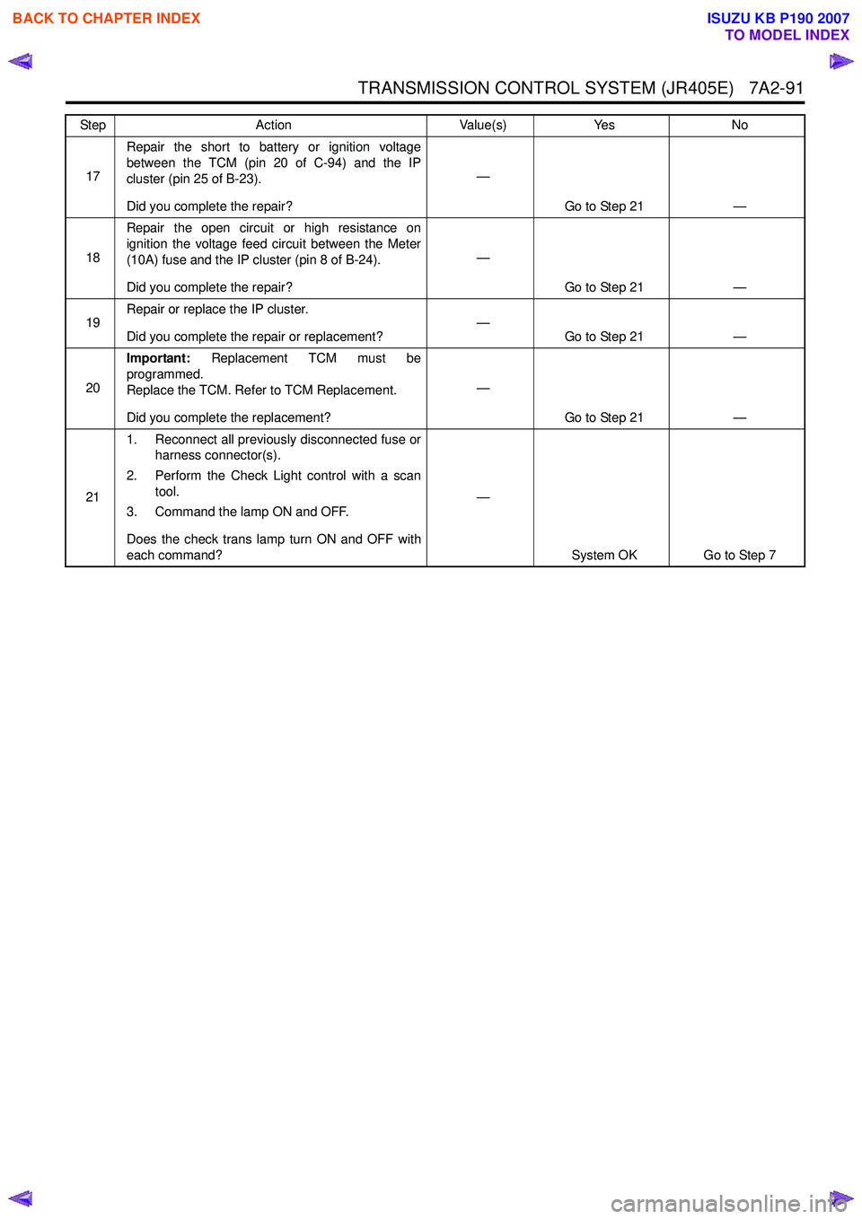
TRANSMISSION CONTROL SYSTEM (JR405E) 7A2-91
17Repair the short to battery or ignition voltage
between the TCM (pin 20 of C-94) and the IP
cluster (pin 25 of B-23).
Did you complete the repair? —
Go to Step 21 —
18 Repair the open circuit or high resistance on
ignition the voltage feed circuit between the Meter
(10A) fuse and the IP cluster (pin 8 of B-24).
Did you complete the repair? —
Go to Step 21 —
19 Repair or replace the IP cluster.
Did you complete the repair or replacement? —
Go to Step 21 —
20 Important:
Replacement TCM must be
programmed.
Replace the TCM. Refer to TCM Replacement.
Did you complete the replacement? —
Go to Step 21 —
21 1. Reconnect all previously disconnected fuse or
harness connector(s).
2. Perform the Check Light control with a scan tool.
3. Command the lamp ON and OFF.
Does the check trans lamp turn ON and OFF with
each command? —
System OK Go to Step 7
Step
Action Value(s)Yes No
BACK TO CHAPTER INDEX
TO MODEL INDEX
ISUZU KB P190 2007
Page 4405 of 6020
TRANSMISSION CONTROL SYSTEM (JR405E) 7A2-121
Test Instructions
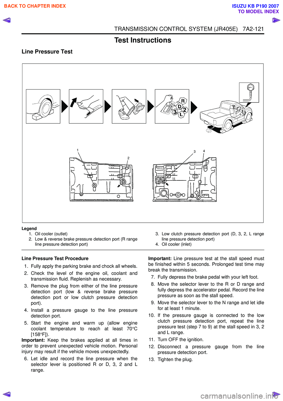
Line Pressure Test
Legend1. Oil cooler (outlet)
2. Low & reverse brake pressure detection port (R range line pressure detection port) 3. Low clutch pressure detection port (D, 3, 2, L range
line pressure detection port)
4. Oil cooler (inlet)
Line Pressure Test Procedure
1. Fully apply the parking brake and chock all wheels.
2. Check the level of the engine oil, coolant and transmission fluid. Replenish as necessary.
3. Remove the plug from either of the line pressure detection port (low & reverse brake pressure
detection port or low clutch pressure detection
port).
4. Install a pressure gauge to the line pressure detection port.
5. Start the engine and warm up (allow engine coolant temperature to reach at least 70 °C
[158 °F]).
Important: Keep the brakes applied at all times in
order to prevent unexpected vehicle motion. Personal
injury may result if the vehicle moves unexpectedly.
6. Let idle and record the line pressure when the selector lever is positioned R or D, 3, 2 and L
range. Important:
Line pressure test at the stall speed must
be finished within 5 seconds. Prolonged test time may
break the transmission.
7. Fully depress the brake pedal with your left foot.
8. Move the selector lever to the R or D range and fully depress the accelerator pedal. Record the line
pressure as soon as the stall speed.
9. Move the selector lever to the N range and let idle for at least 1 minute.
10. If the pressure gauge is connected to the low clutch pressure detection port, repeat the line
pressure test (step 7 to 9) at the stall speed in 3, 2
and L range.
11. Turn OFF the ignition.
12. Disconnect a pressure gauge from the line pressure detection port.
13. Tighten the plug.
1
2 3
4
BACK TO CHAPTER INDEX
TO MODEL INDEX
ISUZU KB P190 2007
Page 4418 of 6020
7A2-134 TRANSMISSION CONTROL SYSTEM (JR405E)
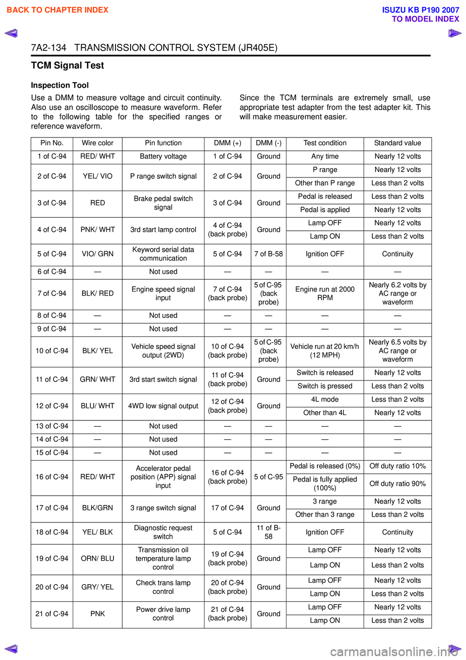
TCM Signal Test
Inspection Tool
Use a DMM to measure voltage and circuit continuity.
Also use an oscilloscope to measure waveform. Refer
to the following table for the specified ranges or
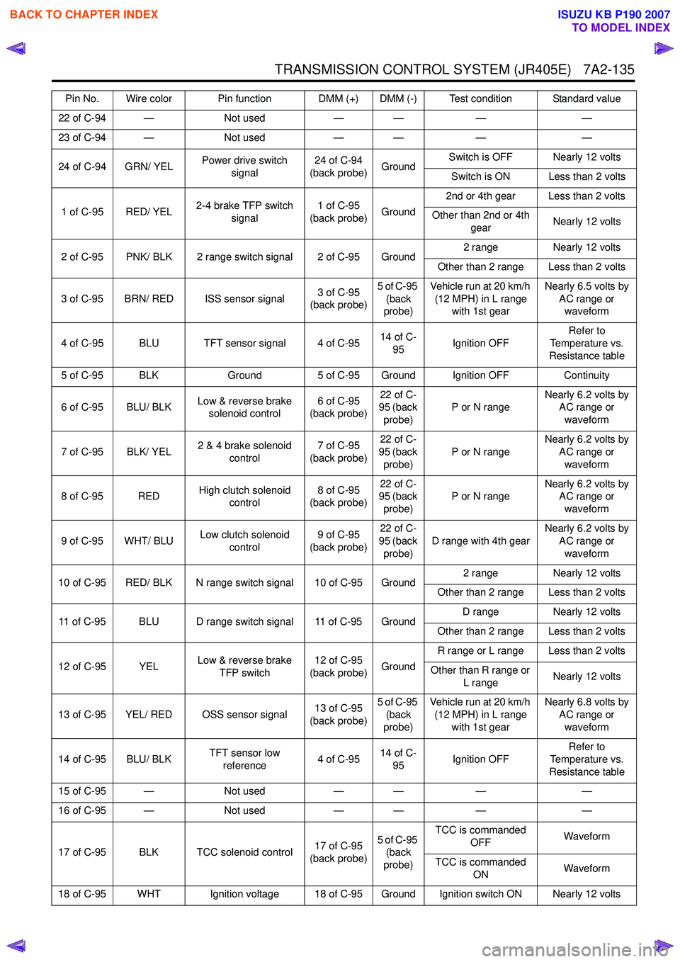
reference waveform. Since the TCM terminals are extremely small, use
appropriate test adapter from the test adapter kit. This
will make measurement easier.
Pin No. Wire color Pin function DMM (+) DMM (-) Test condition Standard value
1 of C-94 RED/ WHT Battery voltage 1 of C-94 Ground Any time Nearly 12 volts
2 of C-94 YEL/ VIO P range switch signal 2 of C-94 Ground P range
Nearly 12 volts
Other than P range Less than 2 volts
3 of C-94 RED Brake pedal switch
signal 3 of C-94 Ground Pedal is released Less than 2 volts
Pedal is applied Nearly 12 volts
4 of C-94 PNK/ WHT 3rd start lamp control 4 of C-94
(back probe) Ground Lamp OFF Nearly 12 volts
Lamp ON Less than 2 volts
5 of C-94 VIO/ GRN Keyword serial data
communication 5 of C-94 7 of B-58 Ignition OFF
Continuity
6 of C-94 — Not used— — ——
7 of C-94 BLK/ RED Engine speed signal
input 7 of C-94
(back probe) 5 of C-95
(back
probe) Engine run at 2000
RPM Nearly 6.2 volts by
AC range or
waveform
8 of C-94 — Not used— — ——
9 of C-94 — Not used— — ——
10 of C-94 BLK/ YEL Vehicle speed signal
output (2WD) 10 of C-94
(back probe) 5 of C-95
(back
probe) Vehicle run at 20 km/h
(12 MPH) Nearly 6.5 volts by
AC range or waveform
11 of C-94 GRN/ WHT 3rd start switch signal 11 of C-94
(back probe) GroundSwitch is released Nearly 12 volts
Switch is pressed Less than 2 volts
12 of C-94 BLU/ WHT 4WD low signal output 12 of C-94
(back probe) Ground 4L mode Less than 2 volts
Other than 4L Nearly 12 volts
13 of C-94 — Not used— — ——
14 of C-94 — Not used— — ——
15 of C-94 — Not used— — ——
16 of C-94 RED/ WHT Accelerator pedal
position (APP) signal
input 16 of C-94
(back probe) 5 of C-95Pedal is released (0%) Off duty ratio 10%
Pedal is fully applied (100%) Off duty ratio 90%
17 of C-94 BLK/GRN 3 range switch signal 17 of C-94 Ground 3 range
Nearly 12 volts
Other than 3 range Less than 2 volts
18 of C-94 YEL/ BLK Diagnostic request
switch 5 of C-9411 o f B -
58 Ignition OFF
Continuity
19 of C-94 ORN/ BLU Transmission oil
temperature lamp control 19 of C-94
(back probe) Ground Lamp OFF Nearly 12 volts
Lamp ON Less than 2 volts
20 of C-94 GRY/ YEL Check trans lamp
control 20 of C-94
(back probe) Ground Lamp OFF Nearly 12 volts
Lamp ON Less than 2 volts
21 of C-94 PNK Power drive lamp
control 21 of C-94
(back probe) Ground Lamp OFF Nearly 12 volts
Lamp ON Less than 2 volts
BACK TO CHAPTER INDEX
TO MODEL INDEX
ISUZU KB P190 2007
Page 4419 of 6020
TRANSMISSION CONTROL SYSTEM (JR405E) 7A2-135
22 of C-94 —Not used— — ——
23 of C-94 — Not used— — ——
24 of C-94 GRN/ YEL Power drive switch
signal 24 of C-94
(back probe) GroundSwitch is OFF Nearly 12 volts
Switch is ON Less than 2 volts
1 of C-95 RED/ YEL 2-4 brake TFP switch
signal 1 of C-95
(back probe) Ground2nd or 4th gear Less than 2 volts
Other than 2nd or 4th gear Nearly 12 volts
2 of C-95 PNK/ BLK 2 range switch signal 2 of C-95 Ground 2 range
Nearly 12 volts
Other than 2 range Less than 2 volts
3 of C-95 BRN/ RED ISS sensor signal 3 of C-95
(back probe) 5 of C-95
(back
probe) Vehicle run at 20 km/h
(12 MPH) in L range with 1st gear Nearly 6.5 volts by
AC range or waveform
4 of C-95 BLU TFT sensor signal 4 of C-95 14 of C-
95 Ignition OFF Refer to
Temperature vs.
Resistance table
5 of C-95 BLK Ground5 of C-95 Ground Ignition OFF Continuity
6 of C-95 BLU/ BLK Low & reverse brake
solenoid control 6 of C-95
(back probe) 22 of C-
95 (back
probe) P or N range
Nearly 6.2 volts by
AC range or
waveform
7 of C-95 BLK/ YEL 2 & 4 brake solenoid
control 7 of C-95
(back probe) 22 of C-
95 (back
probe) P or N range
Nearly 6.2 volts by
AC range or
waveform
8 of C-95 RED High clutch solenoid
control 8 of C-95
(back probe) 22 of C-
95 (back
probe) P or N range
Nearly 6.2 volts by
AC range or
waveform
9 of C-95 WHT/ BLU Low clutch solenoid
control 9 of C-95
(back probe) 22 of C-
95 (back
probe) D range with 4th gear
Nearly 6.2 volts by
AC range or
waveform
10 of C-95 RED/ BLK N range switch signal 10 of C-95 Ground 2 range
Nearly 12 volts
Other than 2 range Less than 2 volts
11 of C-95 BLU D range switch signal 11 of C-95 Ground D range
Nearly 12 volts
Other than 2 range Less than 2 volts
12 of C-95 YEL Low & reverse brake
TFP switch 12 of C-95
(back probe) GroundR range or L range Less than 2 volts
Other than R range or L range Nearly 12 volts
13 of C-95 YEL/ RED OSS sensor signal 13 of C-95
(back probe) 5 of C-95
(back
probe) Vehicle run at 20 km/h
(12 MPH) in L range with 1st gear Nearly 6.8 volts by
AC range or waveform
14 of C-95 BLU/ BLK TFT sensor low
reference 4 of C-9514 of C-
95 Ignition OFF Refer to
Temperature vs.
Resistance table
15 of C-95 — Not used— — ——
16 of C-95 — Not used— — ——
17 of C-95 BLK TCC solenoid control 17 of C-95
(back probe) 5 of C-95
(back
probe) TCC is commanded
OFF Waveform
TCC is commanded ON Waveform
18 of C-95 WHT Ignition voltage 18 of C-95 Ground Ignition switch ON Nearly 12 volts Pin No. Wire color Pin function DMM (+) DMM (-) Test condition Standard value
BACK TO CHAPTER INDEX
TO MODEL INDEX
ISUZU KB P190 2007