2007 ISUZU KB P190 ECO mode
[x] Cancel search: ECO modePage 4003 of 6020
TRANSMISSION CONTROL SYSTEM (AW30–40LE) 7A2-37
2. The TCM must be maintained at a temperature
below 85 °C (185 °F) at all times. This is most
essential if the vehicle is put through a paint baking
process. The TCM will become inoperative if its
temperature exceeds 85 °C (185 °F). Therefore, it is
recommended that the TCM be removed or that
temporary insulation be placed around the TCM
during the time the vehicle is in a paint oven or othe
r
high temperature process.
3. The TCM is designed to process the various inputs and then respond by sending the appropriate
electrical signals to control transmission upshift,
downshift, shift feel and torque converter clutch
engagement.
4. The TCM constantly interprets information from the
various sensors, and controls the systems that
affect transmission and vehicle performance. B
y
analyzing operational problems, the TCM is able to
perform a diagnostic function by displaying DTC(s)
and aid the technician in making repairs.
BACK TO CHAPTER INDEX
TO MODEL INDEX
ISUZU KB P190 2007
Page 4005 of 6020
TRANSMISSION CONTROL SYSTEM (AW30–40LE) 7A2-39
Diagnostic Trouble Code (DTC) Type
Definitions
Emission Related DTC
Action Taken When the DTC Sets - Type A
• The Engine Control Module (ECM) illuminates the
malfunction indicator lamp (MIL) when the
diagnostic runs and fails.
• The ECM records the operating conditions at the
time the diagnostic fails. The ECM stores this
information in the Freeze Frame/ Failure Records.
Action Taken When the DTC Sets - Type B
• The ECM illuminates the MIL on the second
consecutive driving cycle when the diagnostic runs
and fails.
• The ECM records the operating conditions at the
time the diagnostic fails, the ECM stores this
information in the Failure Records. If the
diagnostic reports a failure on the second
consecutive driving cycle, the ECM records the
operating conditions at the time of failure and
stores this information in the Freeze Frame and
updates the Failure Records.
Conditions for Clearing the MIL/ DTC - Type A o
r
Type B • The ECM turns OFF the MIL after 3 consecutive
driving cycles when the diagnostic runs and does
not fail. (Euro 4 Specification)
• The ECM turns OFF the MIL after 1 driving cycle
when the diagnostic runs and does not fail.
(Except Euro 4 Specification)
•
A current DTC clears when the diagnostic runs
and passes after 1 driving cycle.
• A history DTC clears after 40 consecutive warm-
up cycles, if no failures are reported.
• Use a scan tool to clear the MIL and the DTC.
Non-Emissions Related DTCs
Action Taken When the DTC Sets - Type C or Type
D
• The TCM illuminates the Check Trans lamp when
the diagnostic runs and fails.
• The TCM records the operating conditions at the
time the diagnostic fails. The TCM stores this
information in the Failure Records.
• The TCM illuminates the Check Trans on the
second consecutive driving cycle when the
diagnostic runs and fails.
• The TCM records the operating conditions at the
time the diagnostic fails, the TCM stores this
information in the Failure Records. If the
diagnostic reports a failure on the second
consecutive driving cycle, the TCM records the
operating conditions at the time of failure and
stores this information in the Freeze Frame and
updates the Failure Records.
Conditions for Clearing the Check Trans Lamp/ DTC
- Type C or Type D
• The TCM turns OFF the Check Trans lamp after 1
driving cycle when the diagnostic runs and does
not fail.
•
A current DTC clears when the diagnostic runs
and passes after 3 driving cycle.
• A history DTC clears after 40 consecutive warm-
up cycles, if no failures are reported.
• Use a scan tool to clear the Check Trans lamp and
the DTC.
Action Taken When the DTC Sets - Type E or Type F • The TCM will not illuminate the Check Trans lamp.
• The TCM records the operating conditions at the
time the diagnostic fails. The TCM stores this
information in the Failure Records.
Conditions for Clearing the DTC - Type E or Type F •
A current DTC clears when the diagnostic runs
and passes after 1 driving cycle.
• A history DTC clears after 40 consecutive warm-
up cycles, if no failures are reported.
• Use a scan tool to clear the DTC.
BACK TO CHAPTER INDEX
TO MODEL INDEX
ISUZU KB P190 2007
Page 4007 of 6020
TRANSMISSION CONTROL SYSTEM (AW30–40LE) 7A2-41
• All of the following conditions are met.
- Device Control is not operating
- Disable Normal Communication Service is receiving enable
- DTC Clear is not operating
Condition For Setting The DTC
W hen the TCM detects following conditions at 20 times
continuously.
• Ignition voltage is less than 9 volts for 1 second o
r
more continuously. (DTC P0562)
• Ignition voltage is more than 18 volts for 1 second o
r
more continuously. (DTC P0563)
Action Taken When The DTC Sets
• DTC stored.
Conditions For Clearing The DTC
• The DTC can be cleared from the TCM history by
using a scan tool.
• The DTC will be cleared from history when the
vehicle has achieved 40 warm-up cycles without a
failure reported.
•
After more than 1 second has elapsed after the
ignition key has been turned “ON”, short between
No.11 and No.4 (ground) of DLC (Data Link
Connector). Then, after 1 second, but within 6
seconds, discontinue shorting.
Diagnostic Aids
•
Inspect the wiring for poor electrical connection at the
TCM. Look for possible bent, backed out, deformed
or damaged terminals. Check for weak terminal
tension as well. Also check for a chafed wire that
could short to bare metal or other wiring.
Inspect for a broken wire inside the insulation.
• W hen diagnosing for a possible intermittent short o
r
open condition, move the wiring harness while
observing test equipment for a change.
Circuit/System Testing DTC P0562 or P0563
Step Action Value(s) YES NO
1
W as the On-Board Diagnostic (OBD) System Check
performed? — Go to
Step 2 Go to OBD
System Check
2 Using the 5-8840-0285-0 DMM, measure the battery voltage at the battery.
Is the battery voltage greater than the specified value? 11.5 V Go to
Step 3 Charge battery,
then go to Step 3
3 1. Install a scan tool.
2. Select “Ignition Volts” on a scan tool.
3. Start the engine and raise the engine speed to the specified value.
4. Load the electrical system by turning on the headlights, high blower, etc.
Is the ignition voltage approximately equal to the
specified value? More than
1000 rpm
9.0-18.0 V Go to
Step 4 Go to
Starting/
Charging
BACK TO CHAPTER INDEX
TO MODEL INDEX
ISUZU KB P190 2007
Page 4008 of 6020
7A2-42 TRANSMISSION CONTROL SYSTEM (AW30–40LE)
Step Action Value(s) YES NO
4 1. Turn “OFF” the ignition. 2. Disconnect the TCM connector at the TCM.
3. Using the 5-8840-0285-0 DMM, measure the battery voltage between the TCM connector
terminal C94 (Pin No.24)
Is it approximately equal to battery voltage? — Check for
excessive
current with
ignition “OFF”
engine “OFF”. Go to
Step 5
5 1. Check for faulty connections at the TCM harness
terminals.
2. Repair as necessary.
W as a repair necessary? — Go to
Step 8 Go to Step 6
6 1. Check for an open battery feed circuit to the TCM.
2. Repair as necessary.
W as a repair necessary? — Go to
Step 8 Go to Step 7
7 Replace the TCM.
Important: The replacement TCM must be
programmed. (Refer to SPS for procedure.)
W as the action complete? — Go to
Step 8 —
8 1. Reconnect all previously disconnected harness
connector(s).
2. Clear the DTCs with a scan tool.
3. Turn “OFF” the ignition.
4. Start the engine.
5. Operate the vehicle within the Conditions For Running the DTC. You may also operate the
vehicle within the conditions that you observed
from the Freeze Frame/ Failure Records.
Did the DTC fail this ignition? — Go to
Step 2 Go to Step 9
9 Observe the stored information, Capture Info with a
scan tool.
Are there any DTCs that you have not diagnosed? — Go
to
Diagnostic
Trouble Code (DTC) List Verify repair
BACK TO CHAPTER INDEX
TO MODEL INDEX
ISUZU KB P190 2007
Page 4009 of 6020
TRANSMISSION CONTROL SYSTEM (AW30–40LE) 7A2-43
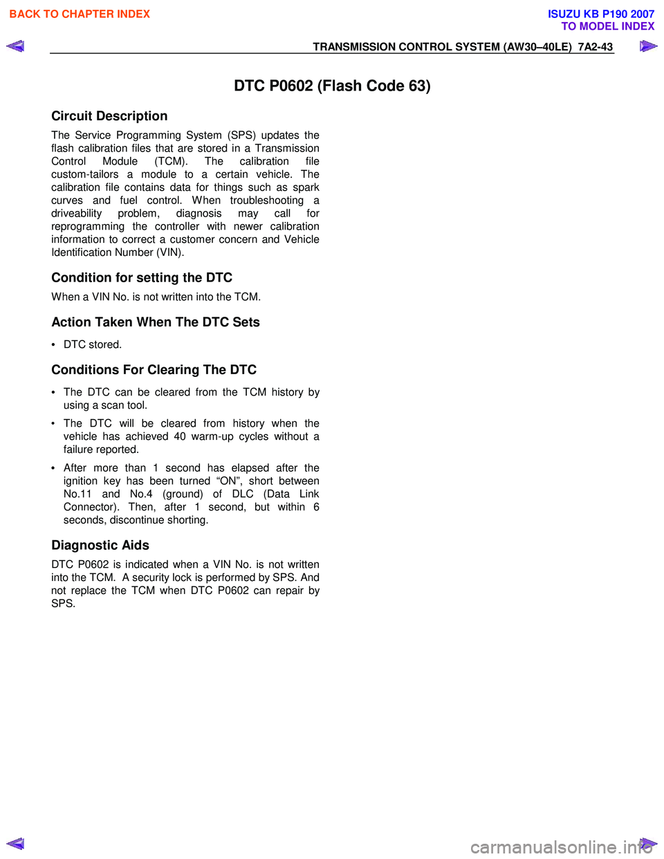
DTC P0602 (Flash Code 63)
Circuit Description
The Service Programming System (SPS) updates the
flash calibration files that are stored in a Transmission
Control Module (TCM). The calibration file
custom-tailors a module to a certain vehicle. The
calibration file contains data for things such as spark
curves and fuel control. W hen troubleshooting a
driveability problem, diagnosis may call fo
r
reprogramming the controller with newer calibration
information to correct a customer concern and Vehicle
Identification Number (VIN).
Condition for setting the DTC
W hen a VIN No. is not written into the TCM.
Action Taken When The DTC Sets
• DTC stored.
Conditions For Clearing The DTC
• The DTC can be cleared from the TCM history by
using a scan tool.
• The DTC will be cleared from history when the vehicle has achieved 40 warm-up cycles without a
failure reported.
•
After more than 1 second has elapsed after the
ignition key has been turned “ON”, short between
No.11 and No.4 (ground) of DLC (Data Link
Connector). Then, after 1 second, but within 6
seconds, discontinue shorting.
Diagnostic Aids
DTC P0602 is indicated when a VIN No. is not written
into the TCM.
A security lock is performed by SPS. And
not replace the TCM when DTC P0602 can repair b
y
SPS.
BACK TO CHAPTER INDEX
TO MODEL INDEX
ISUZU KB P190 2007
Page 4010 of 6020
7A2-44 TRANSMISSION CONTROL SYSTEM (AW30–40LE)
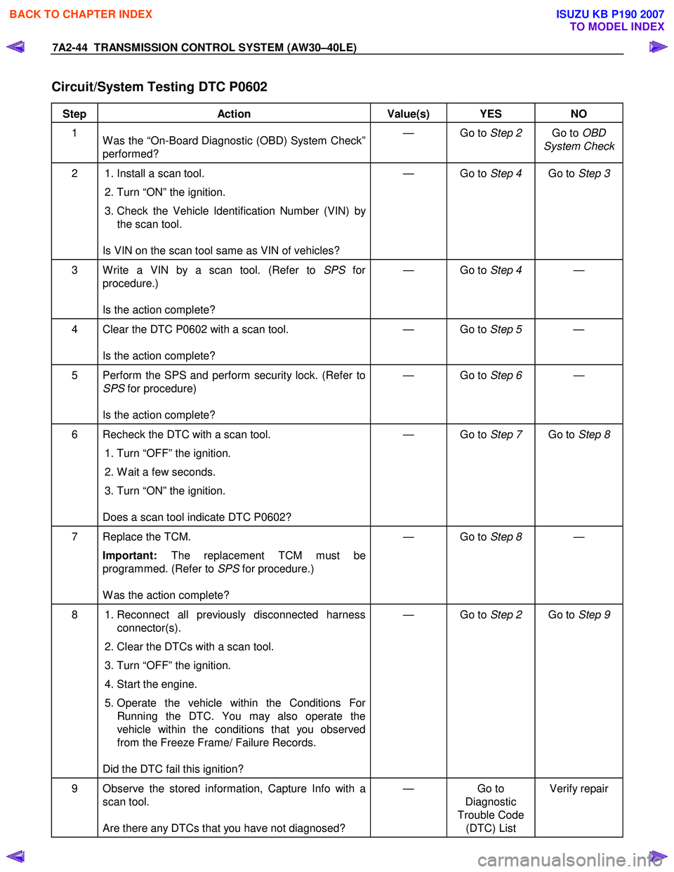
Circuit/System Testing DTC P0602
Step Action Value(s) YES NO
1
W as the “On-Board Diagnostic (OBD) System Check”
performed? — Go to
Step 2 Go to OBD
System Check
2 1. Install a scan tool.
2. Turn “ON” the ignition.
3. Check the Vehicle Identification Number (VIN) by the scan tool.
Is VIN on the scan tool same as VIN of vehicles? — Go to
Step 4 Go to Step 3
3 W rite a VIN by a scan tool. (Refer to SPS for
procedure.)
Is the action complete? — Go to
Step 4 —
4 Clear the DTC P0602 with a scan tool.
Is the action complete? — Go to
Step 5 —
5 Perform the SPS and perform security lock. (Refer to
SPS for procedure)
Is the action complete? — Go to
Step 6 —
6 Recheck the DTC with a scan tool.
1. Turn “OFF” the ignition.
2. W ait a few seconds.
3. Turn “ON” the ignition.
Does a scan tool indicate DTC P0602? — Go to
Step 7 Go to Step 8
7 Replace the TCM.
Important: The replacement TCM must be
programmed. (Refer to SPS for procedure.)
W as the action complete? — Go to
Step 8 —
8 1. Reconnect all previously disconnected harness
connector(s).
2. Clear the DTCs with a scan tool.
3. Turn “OFF” the ignition.
4. Start the engine.
5. Operate the vehicle within the Conditions For Running the DTC. You may also operate the
vehicle within the conditions that you observed
from the Freeze Frame/ Failure Records.
Did the DTC fail this ignition? — Go to
Step 2 Go to Step 9
9 Observe the stored information, Capture Info with a
scan tool.
Are there any DTCs that you have not diagnosed? — Go
to
Diagnostic
Trouble Code (DTC) List Verify repair
BACK TO CHAPTER INDEX
TO MODEL INDEX
ISUZU KB P190 2007
Page 4011 of 6020
TRANSMISSION CONTROL SYSTEM (AW30–40LE) 7A2-45
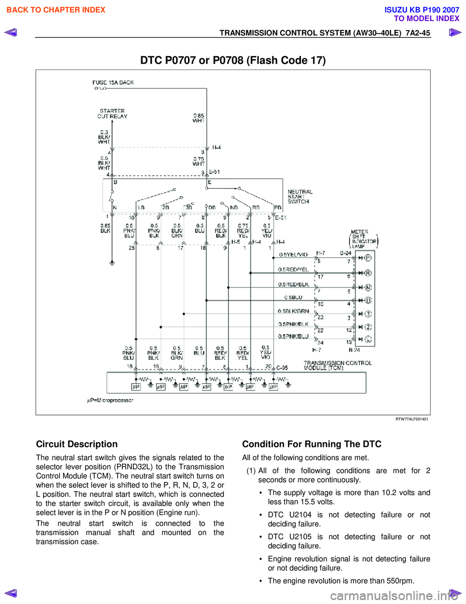
DTC P0707 or P0708 (Flash Code 17)
RTW 77ALF001401
Circuit Description
The neutral start switch gives the signals related to the
selector lever position (PRND32L) to the Transmission
Control Module (TCM). The neutral start switch turns on
when the select lever is shifted to the P, R, N, D, 3, 2 o
r
L position. The neutral start switch, which is connected
to the starter switch circuit, is available only when the
select lever is in the P or N position (Engine run).
The neutral start switch is connected to the
transmission manual shaft and mounted on the
transmission case.
Condition For Running The DTC
All of the following conditions are met.
(1) All of the following conditions are met for 2 seconds or more continuously.
• The supply voltage is more than 10.2 volts and
less than 15.5 volts.
• DTC U2104 is not detecting failure or not
deciding failure.
• DTC U2105 is not detecting failure or not
deciding failure.
• Engine revolution signal is not detecting failure
or not deciding failure.
• The engine revolution is more than 550rpm.
BACK TO CHAPTER INDEX
TO MODEL INDEX
ISUZU KB P190 2007
Page 4012 of 6020
7A2-46 TRANSMISSION CONTROL SYSTEM (AW30–40LE)
(2) Not emergency mode.
(3) All of the following conditions are met. • Device Control is not operating.
• Disable Normal Communication service is
receiving enable.
• DTC Clear is not operating.
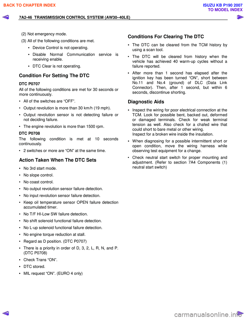
Condition For Setting The DTC
DTC P0707
All of the following conditions are met for 30 seconds or
more continuously.
• All of the switches are “OFF”.
• Output revolution is more than 30 km/h (19 mph).
• Output revolution sensor is not detecting failure o
r
not deciding failure.
• The engine revolution is more than 1500 rpm.
DTC P0708
The following condition is met at 10 seconds
continuously.
• 2 switches or more are “ON” at the same time.
Action Taken When The DTC Sets
• No 3rd start mode.
• No slope control.
• No coast control.
• No output revolution sensor failure detection.
• No input revolution sensor failure detection.
• Keep oil temperature sensor OPEN failure detection accumulated timer.
• No T/F HI-Low SW failure detection.
• No shift solenoid functional failure detection.
• No L-up solenoid functional failure detection.
• No engine torque reduction at stall.
• Regard as D position. (DTC P0707)
• There is a priority in order of D, 3, 2, L, R, N, and P.
(DTC P0708)
• Check Trans “ON”.
• DTC stored.
• MIL request “ON”. (EURO 4 only)
Conditions For Clearing The DTC
•
The DTC can be cleared from the TCM history by
using a scan tool.
• The DTC will be cleared from history when the vehicle has achieved 40 warm-up cycles without a
failure reported.
•
After more than 1 second has elapsed after the
ignition key has been turned “ON”, short between
No.11 and No.4 (ground) of DLC (Data Link
Connector). Then, after 1 second, but within 6
seconds, discontinue shorting.
Diagnostic Aids
• Inspect the wiring for poor electrical connection at the
TCM. Look for possible bent, backed out, deformed
or damaged terminals. Check for weak terminal
tension as well. Also check for a chafed wire that
could short to bare metal or other wiring.
Inspect for a broken wire inside the insulation.
• W hen diagnosing for a possible intermittent short o
r
open condition, move the wiring harness while
observing test equipment for a change.
• Check neutral start switch for proper mounting and adjustment. (Refer to section 7A4 Components (1)
neutral start switch)
BACK TO CHAPTER INDEX
TO MODEL INDEX
ISUZU KB P190 2007