2007 ISUZU KB P190 automatic transmission fluid
[x] Cancel search: automatic transmission fluidPage 4308 of 6020
7A2-24 TRANSMISSION CONTROL SYSTEM (JR405E)
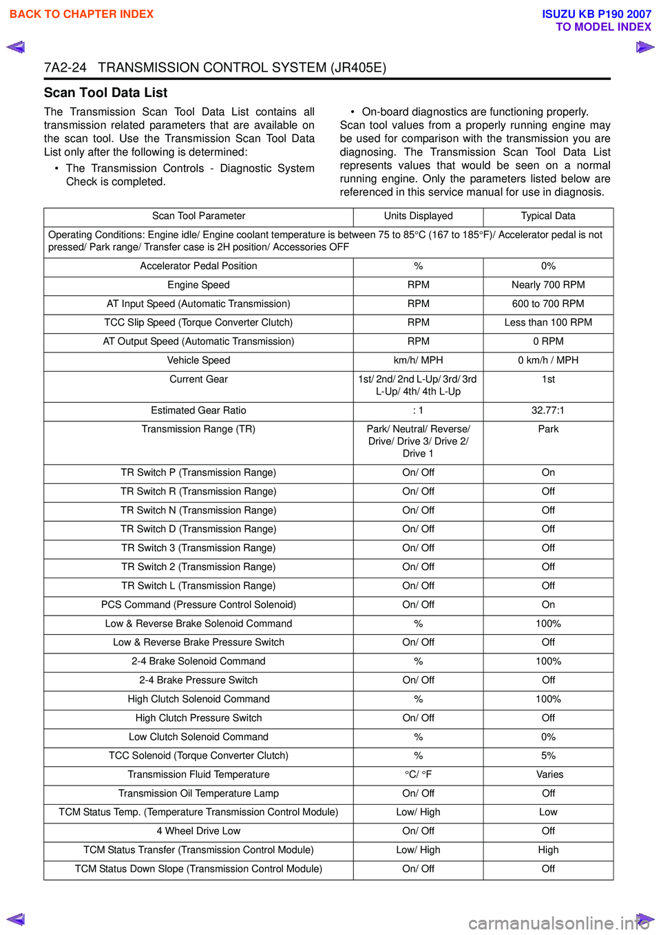
Scan Tool Data List
The Transmission Scan Tool Data List contains all
transmission related parameters that are available on
the scan tool. Use the Transmission Scan Tool Data
List only after the following is determined:
• The Transmission Controls - Diagnostic System Check is completed. • On-board diagnostics are functioning properly.
Scan tool values from a properly running engine may
be used for comparison with the transmission you are
diagnosing. The Transmission Scan Tool Data List
represents values that would be seen on a normal
running engine. Only the parameters listed below are
referenced in this service manual for use in diagnosis.
Scan Tool Parameter Units DisplayedTypical Data
Operating Conditions: Engine idle/ Engine coolant temperature is between 75 to 85 °C (167 to 185 °F)/ Accelerator pedal is not
pressed/ Park range/ Transfer case is 2H position/ Accessories OFF
Accelerator Pedal Position %0%
Engine Speed RPMNearly 700 RPM
AT Input Speed (Automatic Transmission) RPM600 to 700 RPM
TCC Slip Speed (Torque Converter Clutch) RPMLess than 100 RPM
AT Output Speed (Automatic Transmission) RPM0 RPM
Vehicle Speed km/h/ MPH0 km/h / MPH
Current Gear 1st/ 2nd/ 2nd L-Up/ 3rd/ 3rd
L-Up/ 4th/ 4th L-Up 1st
Estimated Gear Ratio : 132.77:1
Transmission Range (TR) Park/ Neutral/ Reverse/
Drive/ Drive 3/ Drive 2/ Drive 1 Park
TR Switch P (Transmission Range) On/ OffOn
TR Switch R (Transmission Range) On/ OffOff
TR Switch N (Transmission Range) On/ OffOff
TR Switch D (Transmission Range) On/ OffOff
TR Switch 3 (Transmission Range) On/ OffOff
TR Switch 2 (Transmission Range) On/ OffOff
TR Switch L (Transmission Range) On/ OffOff
PCS Command (Pressure Control Solenoid) On/ OffOn
Low & Reverse Brake Solenoid Command %100%
Low & Reverse Brake Pressure Switch On/ OffOff
2-4 Brake Solenoid Command %100%
2-4 Brake Pressure Switch On/ OffOff
High Clutch Solenoid Command %100%
High Clutch Pressure Switch On/ OffOff
Low Clutch Solenoid Command %0%
TCC Solenoid (Torque Converter Clutch) %5%
Transmission Fluid Temperature °C/ °F V arie s
Transmission Oil Temperature Lamp On/ OffOff
TCM Status Temp. (Temperature Transmission Control Module) Low/ HighLow
4 Wheel Drive Low On/ OffOff
TCM Status Transfer (Transmission Control Module) Low/ HighHigh
TCM Status Down Slope (Transmission Control Module) On/ OffOff
BACK TO CHAPTER INDEX
TO MODEL INDEX
ISUZU KB P190 2007
Page 4309 of 6020
TRANSMISSION CONTROL SYSTEM (JR405E) 7A2-25
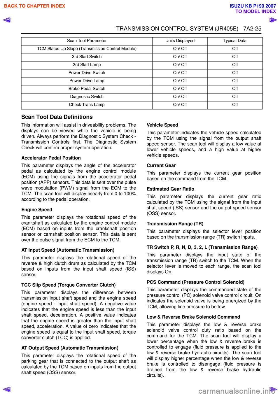
Scan Tool Data Definitions
This information will assist in driveability problems. The
displays can be viewed while the vehicle is being
driven. Always perform the Diagnostic System Check -
Transmission Controls first. The Diagnostic System
Check will confirm proper system operation.
Accelerator Pedal Position
This parameter displays the angle of the accelerator
pedal as calculated by the engine control module
(ECM) using the signals from the accelerator pedal
position (APP) sensors. This data is sent over the pulse
wave modulation (PWM) signal from the ECM to the
TCM. The scan tool will display linearly from 0 to 100%
according to the pedal operation.
Engine Speed
This parameter displays the rotational speed of the
crankshaft as calculated by the engine control module
(ECM) based on inputs from the crankshaft position
sensor or camshaft position sensor. This data is sent
over the pulse signal from the ECM to the TCM.
AT Input Speed (Automatic Transmission)
This parameter displays the rotational speed of the
reverse & high clutch drum as calculated by the TCM
based on inputs from the input shaft speed (ISS)
sensor.
TCC Slip Speed (Torque Converter Clutch)
This parameter displays the difference between
transmission input shaft speed and the engine speed
(engine speed - input shaft speed). A negative value
indicates that the engine speed is less than the input
shaft speed, deceleration. A positive value indicates
that the engine speed is greater than the input shaft
speed, acceleration. A value of zero indicates that the
engine speed is equal to the input shaft speed, torque
converter clutch (TCC) is applied.
AT Output Speed (Automatic Transmission)
This parameter displays the rotational speed of the
parking gear that is connected to the output shaft as
calculated by the TCM based on inputs from the output
shaft speed (OSS) sensor. Vehicle Speed
This parameter indicates the vehicle speed calculated
by the TCM using the signal from the output shaft
speed sensor. The scan tool will display a low value at
lower vehicle speeds, and a high value at higher
vehicle speeds.
Current Gear
This parameter displays the current gear position
based on the command from the TCM.
Estimated Gear Ratio
This parameter displays the current gear ratio
calculated by the TCM using the signal from the input
shaft speed (ISS) sensor and the output speed sensor
(OSS) sensor.
Transmission Range (TR)
This parameter displays the selector lever position
based on the transmission range (TR) switch inputs.
TR Switch P, R, N, D, 3, 2, L (Transmission Range)
This parameter displays the input state of the
transmission range (TR) switch to the TCM. When the
selector lever is moved to each range, the scan tool
displays On.
PCS Command (Pressure Control Solenoid)
This parameter displays the commanded state of the
pressure control (PC) solenoid valve control circuit. On
indicates the solenoid valve is being energized by the
TCM, allowing line pressure to be low.
Low & Reverse Brake Solenoid Command
This parameter displays the low & reverse brake
solenoid valve control duty ratio based on the
command for the TCM. The scan tool will display a
lower percentage when the low & reverse brake is
controlled to engage (fluid pressure is applied to the
low & reverse brake hydraulic circuits). The scan tool
will display higher percentage when the low & reverse
brake is controlled to disengage (fluid pressure is
drained from the low & reverse brake hydraulic
circuits).
TCM Status Up Slope (Transmission Control Module) On/ OffOff
3rd Start Switch On/ OffOff
3rd Start Lamp On/ OffOff
Power Drive Switch On/ OffOff
Power Drive Lamp On/ OffOff
Brake Pedal Switch On/ OffOff
Diagnostic Switch On/ OffOff
Check Trans Lamp On/ OffOff
Scan Tool Parameter
Units DisplayedTypical Data
BACK TO CHAPTER INDEX
TO MODEL INDEX
ISUZU KB P190 2007
Page 4310 of 6020
7A2-26 TRANSMISSION CONTROL SYSTEM (JR405E)
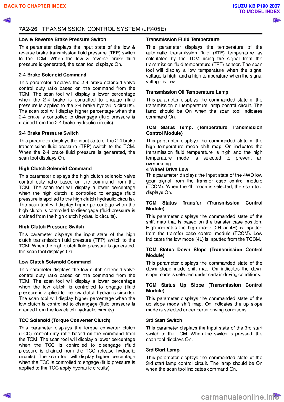
Low & Reverse Brake Pressure Switch
This parameter displays the input state of the low &
reverse brake transmission fluid pressure (TFP) switch
to the TCM. When the low & reverse brake fluid
pressure is generated, the scan tool displays On.
2-4 Brake Solenoid Command
This parameter displays the 2-4 brake solenoid valve
control duty ratio based on the command from the
TCM. The scan tool will display a lower percentage
when the 2-4 brake is controlled to engage (fluid
pressure is applied to the 2-4 brake hydraulic circuits).
The scan tool will display higher percentage when the
2-4 brake is controlled to disengage (fluid pressure is
drained from the 2-4 brake hydraulic circuits).
2-4 Brake Pressure Switch
This parameter displays the input state of the 2-4 brake
transmission fluid pressure (TFP) switch to the TCM.
When the 2-4 brake fluid pressure is generated, the
scan tool displays On.
High Clutch Solenoid Command
This parameter displays the high clutch solenoid valve
control duty ratio based on the command from the
TCM. The scan tool will display a lower percentage
when the high clutch is controlled to engage (fluid
pressure is applied to the high clutch hydraulic circuits).
The scan tool will display higher percentage when the
high clutch is controlled to disengage (fluid pressure is
drained from the high clutch hydraulic circuits).
High Clutch Pressure Switch
This parameter displays the input state of the high
clutch transmission fluid pressure (TFP) switch to the
TCM. When the high clutch fluid pressure is generated,
the scan tool displays On.
Low Clutch Solenoid Command
This parameter displays the low clutch solenoid valve
control duty ratio based on the command from the
TCM. The scan tool will display a lower percentage
when the low clutch is controlled to engage (fluid
pressure is applied to the low clutch hydraulic circuits).
The scan tool will display higher percentage when the
low clutch is controlled to disengage (fluid pressure is
drained from the low clutch hydraulic circuits).
TCC Solenoid (Torque Converter Clutch)
This parameter displays the torque converter clutch
(TCC) control duty ratio based on the command from
the TCM. The scan tool will display a lower percentage
when the TCC is controlled to disengage (fluid
pressure is drained from the TCC release hydraulic
circuits). The scan tool will display higher percentage
when the TCC is controlled to engage (fluid pressure is
applied to the TCC apply hydraulic circuits). Transmission Fluid Temperature
This parameter displays the temperature of the
automatic transmission fluid (ATF) temperature as
calculated by the TCM using the signal from the
transmission fluid temperature (TFT) sensor. The scan
tool will display a low temperature when the signal
voltage is high, and a high temperature when the signal
voltage is low.
Transmission Oil Temperature Lamp
This parameter displays the commanded state of the
transmission oil temperature lamp control circuit. The
lamp should be On when the scan tool indicates
command On.
TCM Status Temp. (Temperature Transmission
Control Module)
This parameter displays the commanded state of the
high temperature mode shift map. On indicates the
transmission fluid temperature is high and the high
temperature mode is selected to prevent an
overheating.
4 Wheel Drive Low
This parameter displays the input state of the 4WD low
gear signal from the transfer case control module
(TCCM). When the 4L mode is selected, the scan tool
displays On.
TCM Status Transfer (Transmission Control
Module)
This parameter displays the commanded state of the
shift map that is based on the transfer case position.
High indicates the high mode (2H or 4H) is inputted
from the transfer case control module (TCCM). Low
indicates the low mode (4L) is inputted from the TCCM.
TCM Status Down Slope (Transmission Control
Module)
This parameter displays the commanded state of the
down slope mode shift map. On indicates the down
slope mode is selected under certain driving conditions.
TCM Status Up Slope (Transmission Control
Module)
This parameter displays the commanded state of the
up slope mode shift map. On indicates the up slope
mode is selected under certin driving conditions.
3rd Start Switch
This parameter displays the input state of the 3rd start
switch to the TCM. When the switch is pressed, the
scan tool displays On.
3rd Start Lamp
This parameter displays the commanded state of the
3rd start lamp control circuit. The lamp should be On
when the scan tool indicates command On.
BACK TO CHAPTER INDEX
TO MODEL INDEX
ISUZU KB P190 2007
Page 4428 of 6020
7A2-144 TRANSMISSION CONTROL SYSTEM (JR405E)
The JR405E automatic transmission is electrically
controlled by a transmission control module (TCM).
There are four forward speeds and one reverse speed.
This JR405E automatic transmission employs a clutch
pressure direct control system (Direct Electronic Shift
Control: DESC) using duty cycle type solenoid valves,
which ensure high shift quality. This transmission also
has a learning function and constantly checks the time
of each clutch and brake required for the shift in order
to match this time with the target value for the optimum
shift. The TCM will automatically select the most
appropriate shift points and lock-up points depending
on the accelerator pedal opening, the vehicle speed
and the vehicle load. If any trouble arises in the speed
sensor, solenoid valve, etc., the fail-safe control
function is activated to keep the running performance.
The JR405E automatic transmission consists of the
torque converter, oil pump, input shaft, out put shaft,
planetary gears and valve body. The gear train consists
of two planetary gear sets and three multiple plate
clutches in combination with two multiple plate brakes
and a one-way clutch.
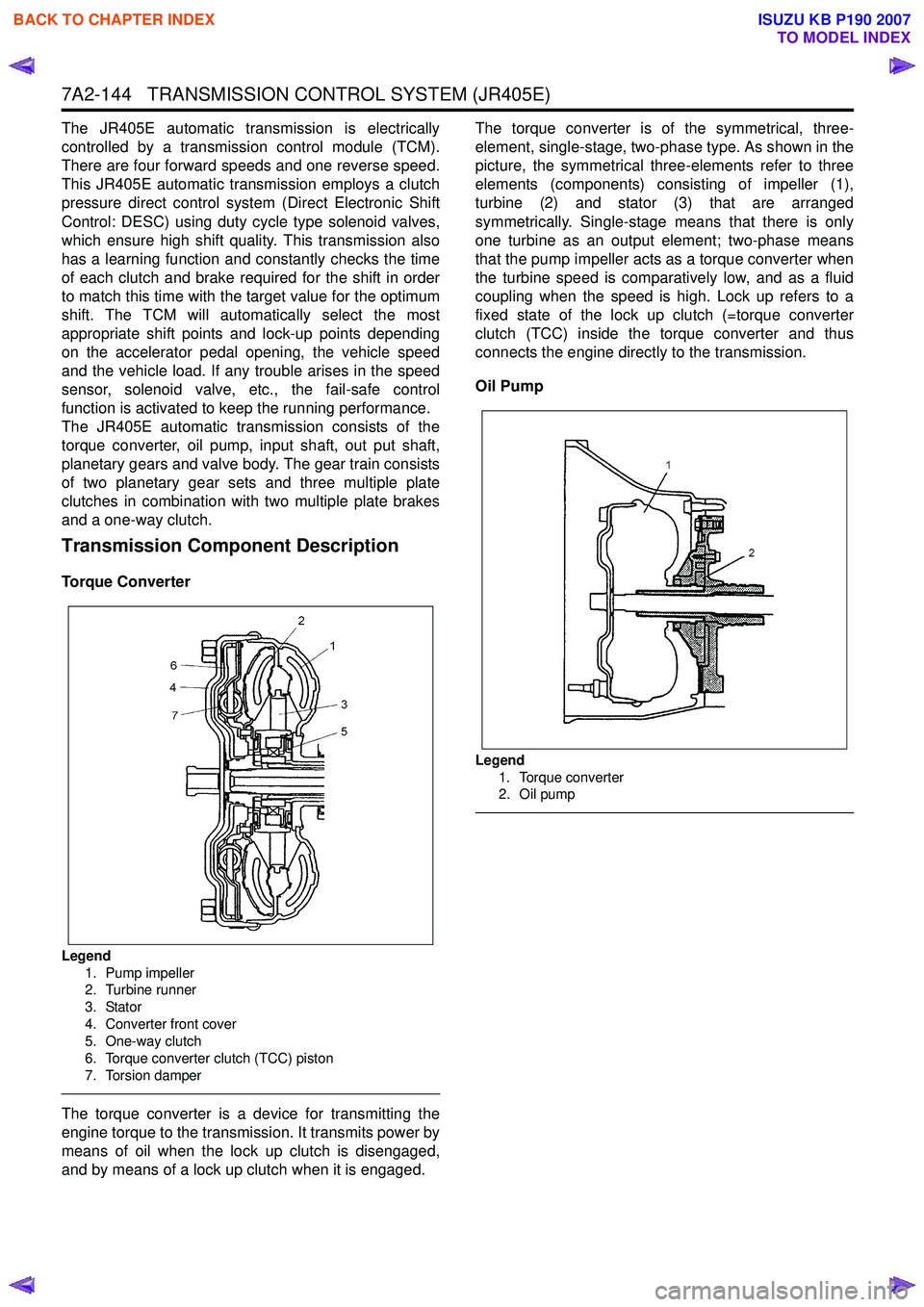
Transmission Component Description
Torque Converter
Legend
1. Pump impeller
2. Turbine runner
3. Stator
4. Converter front cover
5. One-way clutch
6. Torque converter clutch (TCC) piston
7. Torsion damper
The torque converter is a device for transmitting the
engine torque to the transmission. It transmits power by
means of oil when the lock up clutch is disengaged,
and by means of a lock up clutch when it is engaged. The torque converter is of the symmetrical, three-
element, single-stage, two-phase type. As shown in the
picture, the symmetrical three-elements refer to three
elements (components) consisting of impeller (1),
turbine (2) and stator (3) that are arranged
symmetrically. Single-stage means that there is only
one turbine as an output element; two-phase means
that the pump impeller acts as a torque converter when
the turbine speed is comparatively low, and as a fluid
coupling when the speed is high. Lock up refers to a
fixed state of the lock up clutch (=torque converter
clutch (TCC) inside the torque converter and thus
connects the engine directly to the transmission.
Oil Pump
Legend 1. Torque converter
2. Oil pump
BACK TO CHAPTER INDEX
TO MODEL INDEX
ISUZU KB P190 2007
Page 4440 of 6020

7A2-156 TRANSMISSION CONTROL SYSTEM (JR405E)
Gearshift Control & Shift Map Selection
The TCM commands each shift solenoid valve based
on the traveling mode switch (power drive/ 3rd start),
transmission range switch, the vehicle speed, the
accelerator pedal angle and other input signals, to
control the optimum gear position automatically. Shift
features have been set up to the TCM as shift map; the
normal mode is suited to normal travel, and the power
mode is used when the vehicle is loaded or the speed
accelerated. In addition, shift features used only for
high transmission fluid temperature, hill climbing, and
downward travel have been set up to the TCM. These
are automatically switched depending on the driving
conditions. When the transmission fluid temperature is
lower than 10 °C (50 °F), gearshift from the 3rd to the
4th is inhibited.
Shift Map
The TCM selects either of the following shift map
depending on the driving conditions. High Temperature Mode
Condition for setting the high temperature mode shift
map;
• Transmission fluid temperature is more than 122 °C
(252 °F) for 10 seconds.
Condition for canceling the high temperature mode shift
map;
• Transmission fluid temperature is less than 115 °C
(239 °F) for 10 seconds
Notice: High temperature mode may be set with
driving conditions other than the setting condition met
in order to protect from a thermal damage.
3rd Start Mode
Condition for setting the 3rd start mode shift map;
All of the following conditions are met:
• 3rd start switch is pressed
• Vehicle speed is less than 11 km/h (7 MPH)
• Transmission fluid is less than 115 °C (239 °F)
• Accelerator pedal position is less than 8%
• Selector lever is D range
Condition for canceling the 3rd start mode shift map;
Either of the following condition is met:
• 3rd start switch is pressed again
• Vehicle speed is more than 34 km/h (21 MPH)
• Selector lever is other than D range
4L Mode
Condition for setting the 4L mode shift map;
All of the following conditions are met:
• 4L switch is On
• Vehicle speed is more than 5 km/h (3 MPH)
Condition for canceling the 4L mode shift map;
Either of the following condition is met:
• 4L switch is On
• Vehicle speed is more than 5 km/h (3 MPH)
TCM
Sensor inputs
Input shaft speed (ISS) sensor
Output shaft speed (OSS) sensor
Transmission fluid temperature (TFT) sensor
Accelerator pedal position signal (via ECM)
Engine speed signal (via ECM)
Switch inputs
Transmission range (TR) switch
Power drive switch
3rd start switch
Brake pedal switch
4WD low gear signal (via TCCM)
Solenoid valve outputs
Low & reverse brake solenoid valve
2-4 brake solenoid valve
High clutch solenoid valve
Low clutch solenoid valve
Lamp control outputs
Power drive lamp
3rd start lamp
OFF
ON
OFF ON OFF
OFF
Low
Priority Shift map 3rd start
lamp Power drive
lamp
High temperature mode
3rd start mode
4L mode
Down slope mode when
power drive SW Off
Down slope mode when
power drive SW On
Power drive mode
Up slope mode
Normal mode
High
BACK TO CHAPTER INDEX
TO MODEL INDEX
ISUZU KB P190 2007
Page 4455 of 6020
ON-VEHICLE SERVICE (JR405E) 7A3-1
SECTION 7A3
ON-VEHICLE SERVICE (JR405E)
TABLE OF CONTENTS
PAGE
Description ................................................................................................................... ... 7A3 – 2
Automatic Transmission Fluid (ATF) ............................................................................ 7A3 – 2
ATF Level ..................................................................................................................... .... 7A3 – 2
ATF Change .................................................................................................................... . 7A3 – 3
Transmission Control Module (TCM) ............................................................................ 7A3 – 5
Inhibitor Switch .............................................................................................................. . 7A3 – 6
Speed Sensor .................................................................................................................. 7A3 – 8
Turbine Sensor ............................................................................................................... 7A3 – 9
Power and 3rd Start Switch ........................................................................................... 7A3 – 9
Select Lever .................................................................................................................. ... 7A3 –10
Shift Cable ................................................................................................................... .... 7A3 –13
Solenoids, Oil Pressure Switch and Oil Temperature Sensor .................................... 7A3 –16
Control Valve Assembly ................................................................................................. 7A3 –1 8
Flushing the Transmission Fluid Cooler and Line ...................................................... 7A3 –19
Transmission Assembly ................................................................................................. 7A3 –20
Special Service Tool ....................................................................................................... 7A 3 –23
BACK TO CHAPTER INDEX
TO MODEL INDEX
ISUZU KB P190 2007
Page 4456 of 6020
7A3-2 ON-VEHICLE SERVICE (JR405E)
DESCRIPTION
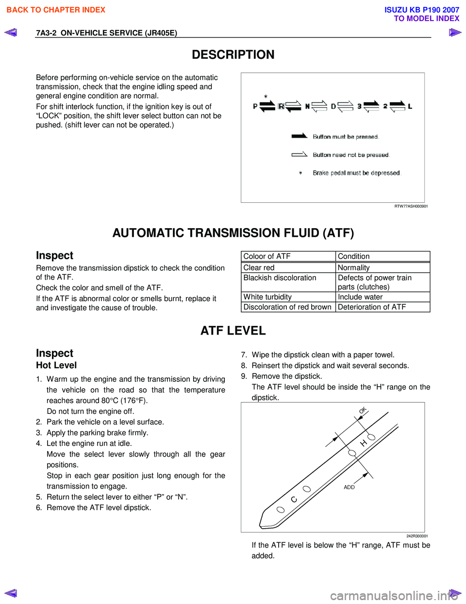
Before performing on-vehicle service on the automatic
transmission, check that the engine idling speed and
general engine condition are normal.
For shift interlock function, if the ignition key is out of
“LOCK” position, the shift lever select button can not be
pushed. (shift lever can not be operated.)
RTW 77ASH000901
AUTOMATIC TRANSMISSION FLUID (ATF)
Inspect
Remove the transmission dipstick to check the condition
of the ATF.
Check the color and smell of the ATF.
If the ATF is abnormal color or smells burnt, replace it
and investigate the cause of trouble.
Coloor of ATF Condition Clear red Normality
Blackish discoloration Defects of power train
parts (clutches)
W hite turbidity Include water
Discoloration of red brown Deterioration of ATF
ATF LEVEL
Inspect
Hot Level
1. W arm up the engine and the transmission by driving
the vehicle on the road so that the temperature
reaches around 80 °C (176 °F).
Do not turn the engine off.
2. Park the vehicle on a level surface.
3. Apply the parking brake firmly.
4. Let the engine run at idle.
Move the select lever slowly through all the gea
r
positions.
Stop in each gear position just long enough for the transmission to engage.
5. Return the select lever to either “P” or “N”.
6. Remove the ATF level dipstick.
7. W ipe the dipstick clean with a paper towel.
8. Reinsert the dipstick and wait several seconds.
9. Remove the dipstick.
The ATF level should be inside the “H” range on the dipstick.
242R300001
If the ATF level is below the “H” range, ATF must be added.
BACK TO CHAPTER INDEX
TO MODEL INDEX
ISUZU KB P190 2007
Page 4473 of 6020
ON-VEHICLE SERVICE (JR405E) 7A3-19
Install or Connect
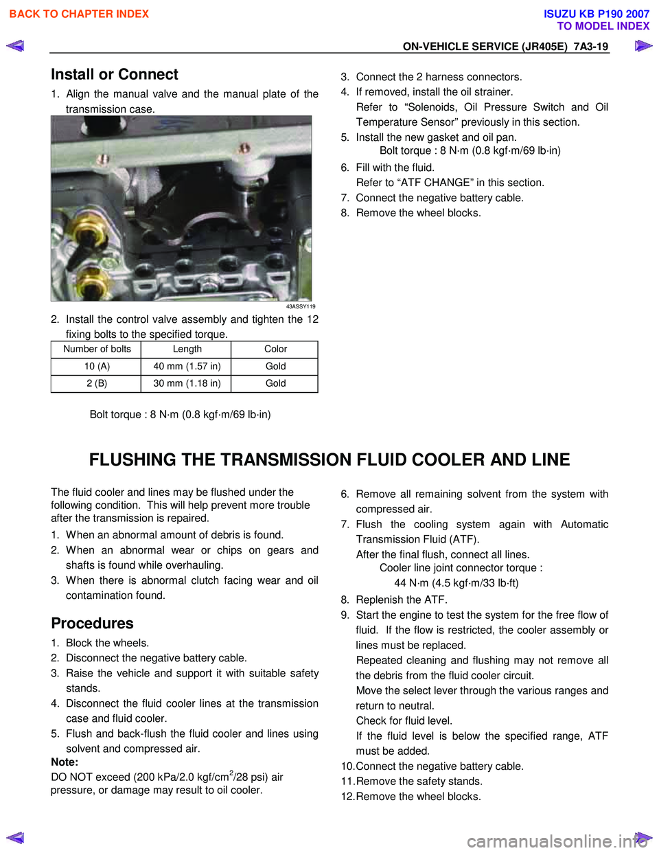
1. Align the manual valve and the manual plate of the
transmission case.
43ASSY119
2. Install the control valve assembly and tighten the 12 fixing bolts to the specified torque.
Number of bolts Length Color
10 (A) 40 mm (1.57 in) Gold
2 (B) 30 mm (1.18 in) Gold
Bolt torque : 8 N·m (0.8 kgf·m/69 lb·in)
3. Connect the 2 harness connectors.
4. If removed, install the oil strainer.
Refer to “Solenoids, Oil Pressure Switch and Oil Temperature Sensor” previously in this section.
5. Install the new gasket and oil pan.
Bolt torque : 8 N·m (0.8 kgf·m/69 lb·in)
6. Fill with the fluid.
Refer to “ATF CHANGE” in this section.
7. Connect the negative battery cable.
8. Remove the wheel blocks.
FLUSHING THE TRANSMISSION FLUID COOLER AND LINE
The fluid cooler and lines may be flushed under the
following condition. This will help prevent more trouble
after the transmission is repaired.
1. W hen an abnormal amount of debris is found.
2. W hen an abnormal wear or chips on gears and shafts is found while overhauling.
3. W hen there is abnormal clutch facing wear and oil contamination found.
Procedures
1. Block the wheels.
2. Disconnect the negative battery cable.
3. Raise the vehicle and support it with suitable safet
y
stands.
4. Disconnect the fluid cooler lines at the transmission case and fluid cooler.
5. Flush and back-flush the fluid cooler and lines using solvent and compressed air.
Note:
DO NOT exceed (200 kPa/2.0 kgf/cm
2/28 psi) air
pressure, or damage may result to oil cooler.
6. Remove all remaining solvent from the system with
compressed air.
7. Flush the cooling system again with Automatic Transmission Fluid (ATF).
After the final flush, connect all lines.
Cooler line joint connector torque :
44 N·m (4.5 kgf·m/33 lb·ft)
8. Replenish the ATF.
9. Start the engine to test the system for the free flow o
f
fluid. If the flow is restricted, the cooler assembly o
r
lines must be replaced.
Repeated cleaning and flushing may not remove all the debris from the fluid cooler circuit.
Move the select lever through the various ranges and return to neutral.
Check for fluid level.
If the fluid level is below the specified range, ATF must be added.
10. Connect the negative battery cable.
11. Remove the safety stands.
12. Remove the wheel blocks.
BACK TO CHAPTER INDEX
TO MODEL INDEX
ISUZU KB P190 2007