2007 ISUZU KB P190 ECO mode
[x] Cancel search: ECO modePage 3800 of 6020
Automatic Transmission – 4L60E – Electrical Diagnosis Page 7C2–14
3 Tech 2 Information
3.1 Tech 2 Diagnostics
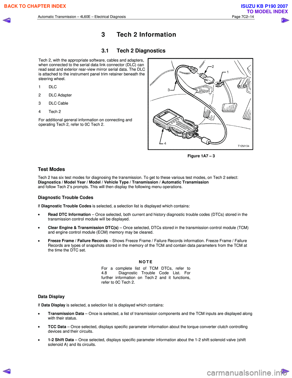
Tech 2, with the appropriate software, cables and adapters,
when connected to the serial data link connector (DLC) can
read seat and exterior rear-view mirror serial data. The DLC
is attached to the instrument panel trim retainer beneath the
steering wheel.
1 DLC
2 DLC Adapter
3 DLC Cable
4 Tech 2
For additional general information on connecting and
operating Tech 2, refer to 0C Tech 2.
Figure 1A7 – 3
Test Modes
Tech 2 has six test modes for diagnosing the transmission. To get to these various test modes, on Tech 2 select:
Diagnostics / Model Year / Model / Vehicle Type / Transmission / Automatic Transmission
and follow Tech 2’s prompts. This will then display the following menu operations.
Diagnostic Trouble Codes
If Diagnostic Trouble Codes is selected, a selection list is displayed which contains:
• Read DTC Information – Once selected, both current and history diagnostic trouble codes (DTCs) stored in the
transmission control module will be displayed.
• Clear Engine & Transmission DTC(s) – Once selected, DTCs stored in the transmission control module (TCM)
and engine control module (ECM) memory may be cleared.
• Freeze Frame / Failure Records – Shows Freeze Frame / Failure Records information. Freeze Frame / Failure
Records are types of snapshots stored in the memory of the TCM and contain data parameters from the TCM at
the time the DTC set.
NOTE
For a complete list of TCM DTCs, refer to
4.8 Diagnostic Trouble Code List. For
further information on Tech 2 and it functions,
refer to 0C Tech 2.
Data Display
If Data Display is selected, a selection list is displayed which contains:
• Transmission Data – Once is selected, a list of transmission components and the TCM inputs are displayed along
with their status.
• TCC Data – Once selected, displays specific parameter information about the torque converter clutch controlling
devices and their circuits.
• 1-2 Shift Data – Once selected, displays specific parameter information about the 1-2 shift solenoid valve (shift
solenoid A) and its circuits.
BACK TO CHAPTER INDEX
TO MODEL INDEX
ISUZU KB P190 2007
Page 3803 of 6020
Automatic Transmission – 4L60E – Electrical Diagnosis Page 7C2–17
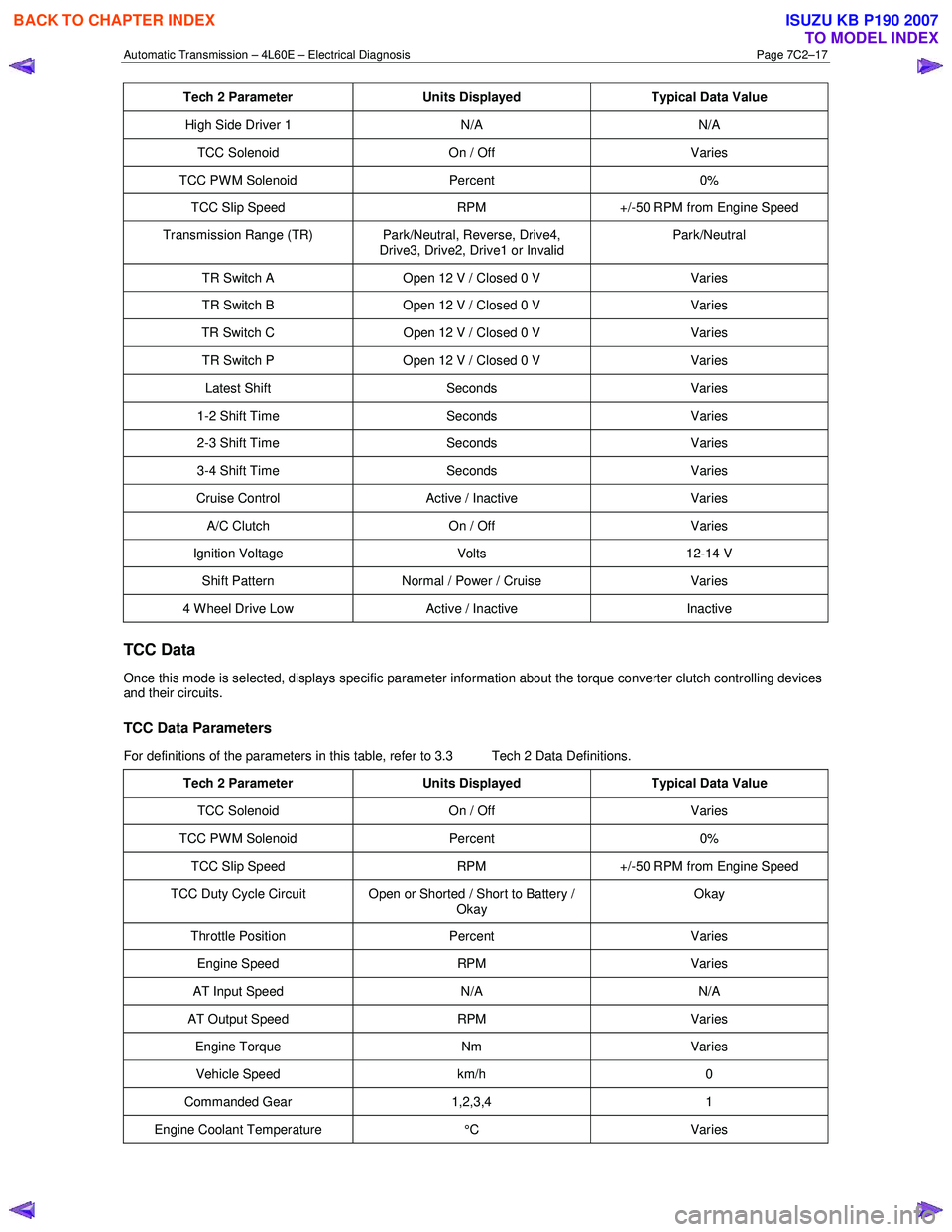
Tech 2 Parameter Units Displayed Typical Data Value
High Side Driver 1 N/A N/A
TCC Solenoid On / Off Varies
TCC PWM Solenoid Percent 0%
TCC Slip Speed RPM +/-50 RPM from Engine Speed
Transmission Range (TR) Park/Neutral, Reverse, Drive4,
Drive3, Drive2, Drive1 or Invalid Park/Neutral
TR Switch A
Open 12 V / Closed 0 V Varies
TR Switch B Open 12 V / Closed 0 V Varies
TR Switch C Open 12 V / Closed 0 V Varies
TR Switch P Open 12 V / Closed 0 V Varies
Latest Shift Seconds Varies
1-2 Shift Time Seconds Varies
2-3 Shift Time Seconds Varies
3-4 Shift Time Seconds Varies
Cruise Control Active / Inactive Varies
A/C Clutch On / Off Varies
Ignition Voltage Volts 12-14 V
Shift Pattern Normal / Power / Cruise Varies
4 Wheel Drive Low Active / Inactive Inactive
TCC Data
Once this mode is selected, displays specific parameter information about the torque converter clutch controlling devices
and their circuits.
TCC Data Parameters
For definitions of the parameters in this table, refer to 3.3 Tech 2 Data Definitions.
Tech 2 Parameter Units Displayed Typical Data Value
TCC Solenoid On / Off Varies
TCC PWM Solenoid Percent 0%
TCC Slip Speed RPM +/-50 RPM from Engine Speed
TCC Duty Cycle Circuit Open or Shorted / Short to Battery /
Okay Okay
Throttle Position
Percent Varies
Engine Speed RPM Varies
AT Input Speed N/A N/A
AT Output Speed RPM Varies
Engine Torque Nm Varies
Vehicle Speed km/h 0
Commanded Gear 1,2,3,4 1
Engine Coolant Temperature °C Varies
BACK TO CHAPTER INDEX
TO MODEL INDEX
ISUZU KB P190 2007
Page 3804 of 6020

Automatic Transmission – 4L60E – Electrical Diagnosis Page 7C2–18
Tech 2 Parameter Units Displayed Typical Data Value
Transmission Fluid Temp °C Varies
Estimated Gear Ratio Ratio 8.00:1
Transmission Hot Mode On / Off Off
1-2 Shift Data
Once this mode is selected, displays specific parameter information about the 1-2 shift solenoid valve and its circuits.
1-2 Shift Data Parameters
For definitions of the parameters in this table, refer to 3.3 Tech 2 Data Definitions.
Tech 2 Parameter Units Displayed Typical Data Value
Shift Solenoid A On / Off Varies
Shift Solenoid B On / Off Varies
Commanded Gear 1,2,3,4 1
1-2 Shift Time Seconds Varies
1-2 Shift Error Seconds Varies
Shift Solenoid A Circuit Open or Shorted / Short to Battery /
Okay Okay
Throttle Position
Percent Varies
Engine Speed RPM Varies
AT Input Speed N/A N/A
AT Output Speed RPM Varies
Vehicle Speed km/h 0
Estimated Gear Ratio Ratio 8.00:1
2-3 Shift Data
Once this mode is selected, displays specific parameter information about the 2-3 shift solenoid valve and its circuits.
2-3 Shift Data Parameters
For definitions of the parameters in this table, refer to 3.3 Tech 2 Data Definitions.
Tech 2 Parameter Units Displayed Typical Data Value
Shift Solenoid A On / Off Varies
Shift Solenoid B On / Off Varies
Commanded Gear 1,2,3,4 1
2-3 Shift Time Seconds Varies
2-3 Shift Error Seconds Varies
Shift Solenoid B Circuit Open or Shorted / Short to Battery /
Okay Okay
Throttle Position
Percent Varies
Engine Speed RPM Varies
AT Input Speed N/A N/A
AT Output Speed RPM Varies
BACK TO CHAPTER INDEX
TO MODEL INDEX
ISUZU KB P190 2007
Page 3805 of 6020
Automatic Transmission – 4L60E – Electrical Diagnosis Page 7C2–19
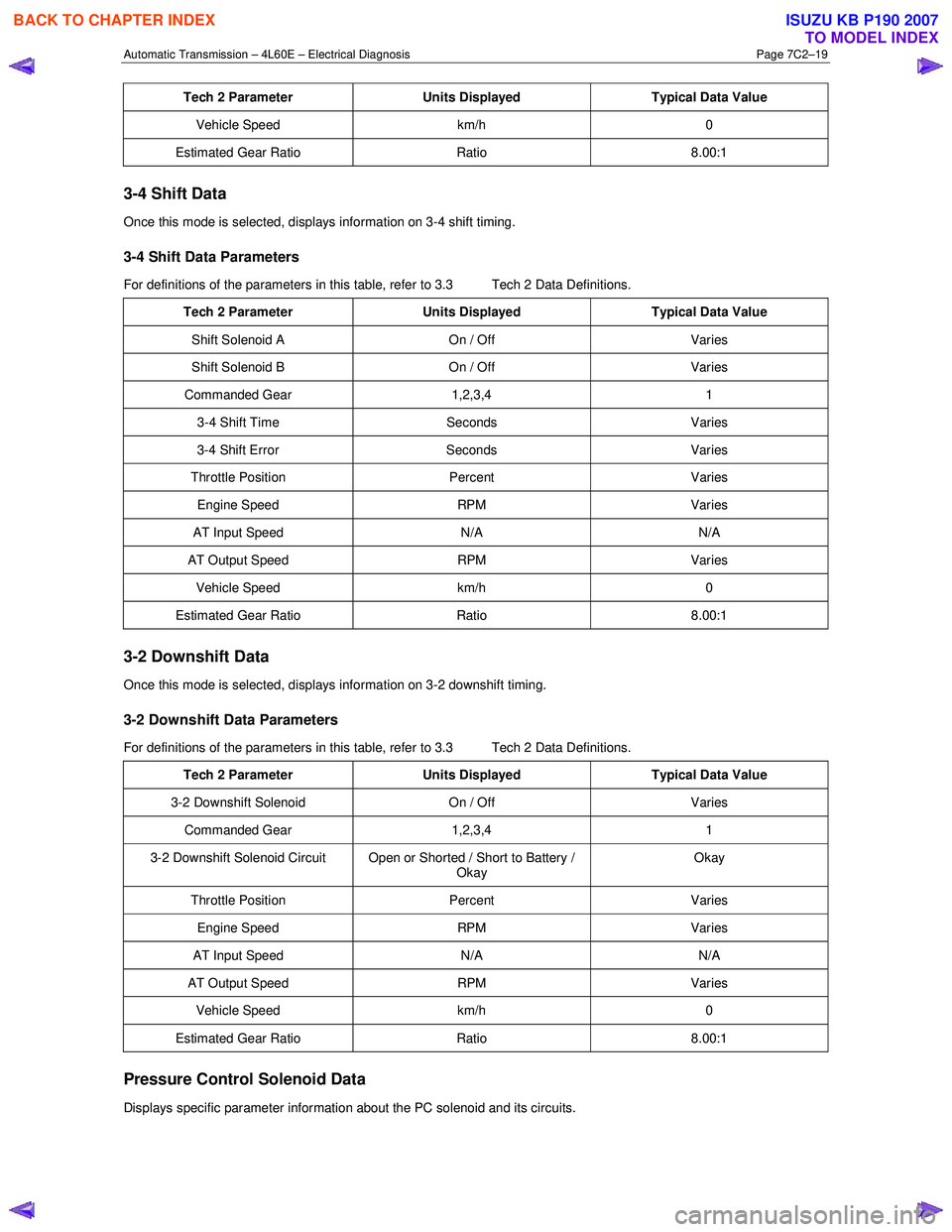
Tech 2 Parameter Units Displayed Typical Data Value
Vehicle Speed km/h 0
Estimated Gear Ratio Ratio 8.00:1
3-4 Shift Data
Once this mode is selected, displays information on 3-4 shift timing.
3-4 Shift Data Parameters
For definitions of the parameters in this table, refer to 3.3 Tech 2 Data Definitions.
Tech 2 Parameter Units Displayed Typical Data Value
Shift Solenoid A On / Off Varies
Shift Solenoid B On / Off Varies
Commanded Gear 1,2,3,4 1
3-4 Shift Time Seconds Varies
3-4 Shift Error Seconds Varies
Throttle Position Percent Varies
Engine Speed RPM Varies
AT Input Speed N/A N/A
AT Output Speed RPM Varies
Vehicle Speed km/h 0
Estimated Gear Ratio Ratio 8.00:1
3-2 Downshift Data
Once this mode is selected, displays information on 3-2 downshift timing.
3-2 Downshift Data Parameters
For definitions of the parameters in this table, refer to 3.3 Tech 2 Data Definitions.
Tech 2 Parameter Units Displayed Typical Data Value
3-2 Downshift Solenoid On / Off Varies
Commanded Gear 1,2,3,4 1
3-2 Downshift Solenoid Circuit Open or Shorted / Short to Battery /
Okay Okay
Throttle Position
Percent Varies
Engine Speed RPM Varies
AT Input Speed N/A N/A
AT Output Speed RPM Varies
Vehicle Speed km/h 0
Estimated Gear Ratio Ratio 8.00:1
Pressure Control Solenoid Data
Displays specific parameter information about the PC solenoid and its circuits.
BACK TO CHAPTER INDEX
TO MODEL INDEX
ISUZU KB P190 2007
Page 3806 of 6020
Automatic Transmission – 4L60E – Electrical Diagnosis Page 7C2–20
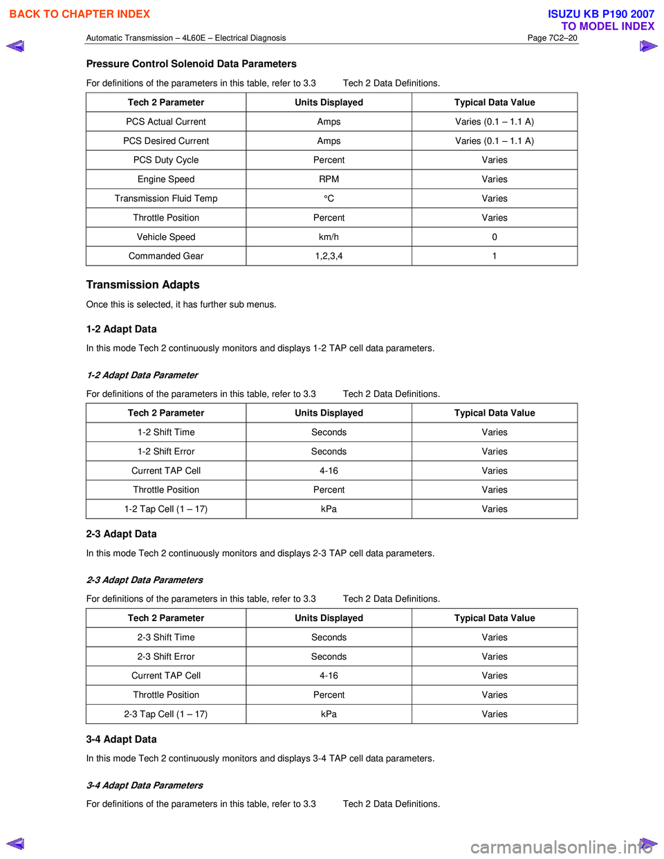
Pressure Control Solenoid Data Parameters
For definitions of the parameters in this table, refer to 3.3 Tech 2 Data Definitions.
Tech 2 Parameter Units Displayed Typical Data Value
PCS Actual Current Amps Varies (0.1 – 1.1 A)
PCS Desired Current Amps Varies (0.1 – 1.1 A)
PCS Duty Cycle Percent Varies
Engine Speed RPM Varies
Transmission Fluid Temp °C Varies
Throttle Position Percent Varies
Vehicle Speed km/h 0
Commanded Gear 1,2,3,4 1
Transmission Adapts
Once this is selected, it has further sub menus.
1-2 Adapt Data
In this mode Tech 2 continuously monitors and displays 1-2 TAP cell data parameters.
1-2 Adapt Data Parameter
For definitions of the parameters in this table, refer to 3.3 Tech 2 Data Definitions.
Tech 2 Parameter Units Displayed Typical Data Value
1-2 Shift Time Seconds Varies
1-2 Shift Error Seconds Varies
Current TAP Cell 4-16 Varies
Throttle Position Percent Varies
1-2 Tap Cell (1 – 17) kPa Varies
2-3 Adapt Data
In this mode Tech 2 continuously monitors and displays 2-3 TAP cell data parameters.
2-3 Adapt Data Parameters
For definitions of the parameters in this table, refer to 3.3 Tech 2 Data Definitions.
Tech 2 Parameter Units Displayed Typical Data Value
2-3 Shift Time Seconds Varies
2-3 Shift Error Seconds Varies
Current TAP Cell 4-16 Varies
Throttle Position Percent Varies
2-3 Tap Cell (1 – 17) kPa Varies
3-4 Adapt Data
In this mode Tech 2 continuously monitors and displays 3-4 TAP cell data parameters.
3-4 Adapt Data Parameters
For definitions of the parameters in this table, refer to 3.3 Tech 2 Data Definitions.
BACK TO CHAPTER INDEX
TO MODEL INDEX
ISUZU KB P190 2007
Page 3807 of 6020
Automatic Transmission – 4L60E – Electrical Diagnosis Page 7C2–21
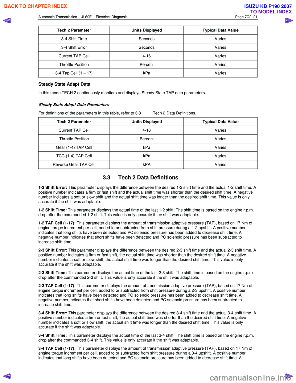
Tech 2 Parameter Units Displayed Typical Data Value
3-4 Shift Time Seconds Varies
3-4 Shift Error Seconds Varies
Current TAP Cell 4-16 Varies
Throttle Position Percent Varies
3-4 Tap Cell (1 – 17) kPa Varies
Steady State Adapt Data
In this mode TECH 2 continuously monitors and displays Steady State TAP data parameters.
Steady State Adapt Data Parameters
For definitions of the parameters in this table, refer to 3.3 Tech 2 Data Definitions.
Tech 2 Parameter Units Displayed Typical Data Value
Current TAP Cell 4-16 Varies
Throttle Position Percent Varies
Gear (1-4) TAP Cell kPa Varies
TCC (1-4) TAP Cell kPa Varies
Reverse Gear TAP Cell kPA Varies
3.3 Tech 2 Data Definitions
1-2 Shift Error: This parameter displays the difference between the desired 1-2 shift time and the actual 1-2 shift time. A
positive number indicates a firm or fast shift and the actual shift time was shorter than the desired shift time. A negative
number indicates a soft or slow shift and the actual shift time was longer than the desired shift time. This value is only
accurate if the shift was adaptable.
1-2 Shift Time: This parameter displays the actual time of the last 1-2 shift. The shift time is based on the engine r.p.m.
drop after the commanded 1-2 shift. This value is only accurate if the shift was adaptable.
1-2 TAP Cell (1-17): This parameter displays the amount of transmission adaptive pressure (TAP), based on 17 Nm of
engine torque increment per cell, added to or subtracted from shift pressure during a 1-2 upshift. A positive number
indicates that long shifts have been detected and PC solenoid pressure has been added to decrease shift time. A
negative number indicates that short shifts have been detected and PC solenoid pressure has been subtracted to
increase shift time.
2-3 Shift Error: This parameter displays the difference between the desired 2-3 shift time and the actual 2-3 shift time. A
positive number indicates a firm or fast shift, the actual shift time was shorter than the desired shift time. A negative
number indicates a soft or slow shift, the actual shift time was longer than the desired shift time. This value is only
accurate if the shift was adaptable.
2-3 Shift Time: This parameter displays the actual time of the last 2-3 shift. The shift time is based on the engine r.p.m
drop after the commanded 2-3 shift. This value is only accurate if the shift was adaptable.
2-3 TAP Cell (1-17): This parameter displays the amount of transmission adaptive pressure (TAP), based on 17 Nm of
engine torque increment per cell, added to or subtracted from shift pressure during a 2-3 upshift. A positive number
indicates that long shifts have been detected and PC solenoid pressure has been added to decrease shift time. A
negative number indicates that short shifts have been detected and PC solenoid pressure has been subtracted to
increase shift time.
3-4 Shift Error: This parameter displays the difference between the desired 3-4 shift time and the actual 3-4 shift time. A
positive number indicates a firm or fast shift, the actual shift time was shorter than the desired shift time. A negative
number indicates a soft or slow shift, the actual shift time was longer than the desired shift time. This value is only
accurate if the shift was adaptable.
3-4 Shift Time: This parameter displays the actual time of the last 3-4 shift. The shift time is based on the engine r.p.m.
drop after the commanded 3-4 shift. This value is only accurate if the shift was adaptable.
3-4 TAP Cell (1-17): This parameter displays the amount of transmission adaptive pressure (TAP), based on 17 Nm of
engine torque increment per cell, added to or subtracted from shift pressure during a 3-4 upshift. A positive number
indicates that long shifts have been detected and PC solenoid pressure has been added to decrease shift time. A
BACK TO CHAPTER INDEX
TO MODEL INDEX
ISUZU KB P190 2007
Page 3809 of 6020
Automatic Transmission – 4L60E – Electrical Diagnosis Page 7C2–23
TFP Gear: This parameter displays Park/Neutral, Reverse , Drive4 , Drive3 , Drive2 , Drive1 or Invalid . This parameter
is the decoded status of the three A/B/C inputs from the automatic transmission fluid pressure manual valve position
switch. If a valid combination of inputs is not detected, invalid will be displayed.
TFP Swi A/B/C: This parameter displays Open 12 V / Closed 0 V for each switch. This parameter indicates the statues
of the three inputs from the automatic transmission fluid pressure manual valve position switch assembly.
Throttle Position: This parameter displays a calculated value, which is determined by the accelerator pedal position and
the actual throttle position, used to optimise transmission controls. It represents the driver’s intended requested for
torque or acceleration. The range is 0-100%, 0% represents an idle or coast request and 100% represents a request for
wide open throttle (WOT).
Torque Converter Efficiency: This parameter displays a ratio of 0.00:1 to 2:1. The ratio is calculates by multiplying the
speed ratio by a value related to the ‘K factor’ of the torque converter. The ‘K factor’ is the looseness or tightness of the
torque converter for a given torque. The nearer the torque converter is to full coupling, i.e. 1:1, the closer the torque
converter efficiency number will be to 1.
TR Switch A/B/C/P: This parameter displays the status of the four inputs from the transmission range switch. Tech 2
displays Open 12V / Closed 0 V . Open 12 V indicates an ignition voltage input to the control module. Closed 0 V
indicates a zero voltage input to the control module.
Transmission Fluid Temperature: This parameter displays the input signal of the transmission fluid temperature sensor.
Transmission fluid temperature is high, 151°C, when signal voltage is low, 0 V. Transmission fluid temperature is low, -
40°C, when signal voltage is high, 5 V.
Transmission Hot Mode: This parameter displays the automatic transmission fluid temperature (TFT) and displays On
or Off . Off indicates the TFT has not exceeded 130°C. On indicates the TFT has exceeded 130°C and has not cooled to
120°C for greater than 5 seconds. These numbers are approximate and differ with transmissions.
Vehicle Speed: This parameter displays the speed at which the vehicle is travelling. Tech 2 displays vehicle speed as
kilometres per hour (km/h). The vehicle speed is calculates based on the input signal from the automatic transmission
output shaft speed sensor.
3.4 Miscellaneous Tests
Tech 2
Miscellaneous Tests Description
Shift Solenoid A •
The TCM commands the 1-2 shift solenoid valve on and off. Tech 2’s Shift Solenoid A
Parameter should match the commanded state. Tech 2’s Commanded Gear
parameter should correspond with the shift solenoid combination. Refer to
5.6 Shift Solenoid Valve State and Gear Ratio.
• When the ignition is on, and the engine is off, there no limits to this control. The
solenoid remains on until commanded off, and vice versa. W hen the test is exited, the
solenoid state is determined by the TCM.
• W hen the engine is running, the following control limits apply:
• Only sequential gear changes are allowed. For example, 1
st to 3rd is not allowed.
If a non-sequential gear change is attempted, the message Non-sequential
gear changes not allowed . Gear changes must be made in order appears
on Tech 2.
• The vehicle speed must be below a calibrated value. If the vehicle speed is too
high, the message Vehicle speed too high appears on Tech 2.
• The engine speed must be below a calibrated value. If the engine speed is too
high, the message Engine speed too high appears on Tech 2.
• Downshifts are allowed only when the vehicle speed is below a calibrated value.
If the vehicle speed is too high, the message Eng. is on and veh. speed to hi
for 3-2 or 2-1 downshift appears on Tech 2.
• The gear requested may not be greater than the current selected transmission
range (PRNDL). For example, 3
rd gear is not allowed if the transmission range is
D2. If the gear requested is greater than the current selected transmission
range, the message Eng. running and gear request is greater than the
current TR appears on Tech 2.
• The solenoid remains on until commanded off, and vice versa. W hen the test is
exited, the solenoid state is determined by the TCM.
BACK TO CHAPTER INDEX
TO MODEL INDEX
ISUZU KB P190 2007
Page 3813 of 6020
Automatic Transmission – 4L60E – Electrical Diagnosis Page 7C2–27
4 Diagnostics
4.1 Introduction
The transmission diagnostic procedure is organised in a logical structure that begins with the diagnostic system check
and as such must always be used as the starting point. The diagnostic system check directs the technician to the logical
steps necessary to diagnose a transmission driveability fault condition.
4.2 Basic Knowledge Required
A lack of basic understanding regarding
electronics, electrical wiring circuits and use
of electrical circuit testing tools when
performing any diagnostic procedure, could
result in incorrect diagnostic results or
damage to system components.
Understanding of the following is required to perform any of the diagnostic procedures detailed in this Service
Information:
• Basic electronics,
• Electrical wiring circuits,
• Electrical circuits testing, and
• Correct use of basic system diagnostic tools.
4.3 Diagnostic Precautions
When tests are required on connector
terminals, use the adapters in connector
adaptor kit J35616-C to prevent damage to
terminals.
The following precautions must be observed when performing all diagnostic procedures. Otherwise, incorrect diagnostic
results or damage to system components will occur:
1 Disconnection of the battery affects certain vehicle electronic systems.
2 Disconnect the battery negative lead when performing the following procedures:
• Disconnecting the electronic control module wiring harness connector/s or
• Charging the battery.
3 Disconnect the battery terminal ground lead and the electronic control module wiring harness connector before attempting any electric arc welding on the vehicle.
4 Do not start the engine if the battery terminal is not properly secured to the battery.
5 Do not disconnect or reconnect any of the following while the ignition is switched on or when the engine is running:
• Any electronic control module or system component electrical wiring connector, or
• Battery terminal leads.
6 Ensure that the correct procedure for disconnecting and connecting system electrical wiring harness connectors is always followed. For information on the correct procedure for disconnecting and connecting specific wiring
connectors, refer to 8A Electrical-Body and Chassis.
BACK TO CHAPTER INDEX
TO MODEL INDEX
ISUZU KB P190 2007