Page 4441 of 6020
 7A2-157
Down Slope Mode
Condition for setting the down slope mode shift map;
All of the following conditions are met:
• Brake pedal switch is depressed
�")
TRANSMISSION CONTROL SYSTEM (JR405E) 7A2-157
Down Slope Mode
Condition for setting the down slope mode shift map;
All of the following conditions are met:
• Brake pedal switch is depressed
• Accelerator pedal is released
• Vehicle speed is more than 60 km/h (36 MPH)
• Increment of vehicle speed is more than 1 km/h (1 MPH) per second
• Selector lever is D or 3 range
Condition for canceling the down slope mode shift map;
Either of the following condition is met:
• Accelerator pedal is depressed
• Selector lever is other than D or 3 range Power Drive Mode
When the power drive switch is ON, the TCM switches
shift map to the power drive mode map and performs
gearshift control from 1st to 4th to gain more
acceleration compared with normal mode.
Up Slope Mode
Up slope reasoning value is calculated from the
averaged accelerator pedal angle and the averaged
acceleration. Otherwise, up slope reasoning value is
calculated from the vehicle speed. The TCM selects a
up slope mode when the former is bigger than the
latter.
Lock Up Control
Legend 1. TCC solenoid valve
2. Solenoid fluid pressure
3. Lock up control spool valve
4. Torque converter clutch (TCC) 5. Torque converter front cover
6. TCC engagement fluid pressure
7. TCC disengagement fluid pressure
TCM
Sensor inputs
Input shaft speed (ISS) sensor
Output shaft speed (OSS) sensor
Transmission fluid temperature (TFT) sensor
Accelerator pedal position signal (via ECM)
Engine speed signal (via ECM)
Solenoid valve outputsTorque converter clutch (TCC) solenoid valve
BACK TO CHAPTER INDEX
TO MODEL INDEX
ISUZU KB P190 2007
Page 4442 of 6020

The TCM controls the torque converter clutch (TCC)
solenoid valve based on the accelerator pedal angle,
input shaft speed, output shaft speed and transm")
7A2-158 TRANSMISSION CONTROL SYSTEM (JR405E)
The TCM controls the torque converter clutch (TCC)
solenoid valve based on the accelerator pedal angle,
input shaft speed, output shaft speed and transmission
fluid temperature.
Smooth lock up control is employed to engage or
disengage the TCC smoothly at the time of lock up On
or Off. When the TCM determines the TCC
engagement, the solenoid valve control duty cycle
(pulse width modulation [PWM]) signal is gradually
increased (5% to 95%) and the transmission fluid
between the TCC piston and torque converter front
cover is gradually drained. As a result, the TCC piston
is fitted slowly to the torque converter front cover under
fluid pressure securing smooth lock up engagement. The lock up control does not start when the
transmission fluid temperature is less than 20 °C (68 °F)
even though the vehicle is at the lock up control speed
area. The lock up control disengages when the
accelerator pedal angle is released.
Direct Electronic Shift Control (DECS)
Legend 1. Oil pump
2. Pressure regulator spool valve
3. ON/ OFF type solenoid valve (pressure control [PC]
solenoid valve 4. Duty cycle type solenoid valve (shift solenoid valve)
5. Amplifier (AMP) valve
6. Clutch
Solenoid valve outputs
Pressure control (PC) solenoid valve
Low & reverse brake solenoid valve
2-4 brake solenoid valve
High clutch solenoid valve
Low clutch solenoid valve
TCM
Sensor inputsInput shaft speed (ISS) sensor
Output shaft speed (OSS) sensor
Transmission fluid temperature (TFT) sensor
Accelerator pedal position signal (via ECM)
Engine speed signal (via ECM)
Switch inputs
Low & reverse brake transmission fluid
pressure (TFP) switch
2-4 brake transmission fluid pressure (TFP)
switch
High clutch transmission fluid pressure (TFP)
switch
BACK TO CHAPTER INDEX
TO MODEL INDEX
ISUZU KB P190 2007
Page 4443 of 6020
 7A2-159
Based on each transmission fluid pressure (TFP)
switch signal and each speed sensor signal and the
accelerator pedal angle, the duty cycle type shift
so")
TRANSMISSION CONTROL SYSTEM (JR405E) 7A2-159
Based on each transmission fluid pressure (TFP)
switch signal and each speed sensor signal and the
accelerator pedal angle, the duty cycle type shift
solenoid valve adjusts the clutch pressure to match the
engine load and vehicle running conditions. Controlling
the engagement and disengagement of the clutch and
brake pressure is directly and accurately controlled via
TCM, which is different to the conventional accumulator
type. Instead of the conventional system (On/ Off type
shift solenoid valve and shift valve), the combination of
the duty cycle type solenoid valve and the amplifier
(AMP) valve are used to adjust the clutch pressure to
match the engine load and vehicle driving conditions,
based on the signal from the TCM. Also, the TFP
switch provided in the fluid passage of the control valve
transmits to TCM, enabling the engagement and
disengagement control of the clutch and brake to be
directly and finely. When the gear is shifted from the
2nd to 3rd, 3rd to 4th, 4th to 3rd and 3rd to 2nd, the
clutch pressures on the engagement side and
disengagement side are simultaneously controlled. As
a result, engine racing or clutch drag is prevented
which enables a smooth and quick shift response.
Learning Control
Solenoid valve outputs
Low & reverse brake solenoid valve
2-4 brake solenoid valve
High clutch solenoid valve
Low clutch solenoid valve
TCM
Sensor inputs Input shaft speed (ISS) sensor
Output shaft speed (OSS) sensor
Transmission fluid temperature (TFT) sensor
Accelerator pedal position signal (via ECM)
Engine speed signal (via ECM)
Switch inputs
Low & reverse brake transmission fluid
pressure (TFP) switch
2-4 brake transmission fluid pressure (TFP)
switch
High clutch transmission fluid pressure (TFP)
switch
BACK TO CHAPTER INDEX
TO MODEL INDEX
ISUZU KB P190 2007
Page 4456 of 6020

DESCRIPTION
Before performing on-vehicle service on the automatic
transmission, check that the engine idling speed and
general engine condition are normal.
Fo")
7A3-2 ON-VEHICLE SERVICE (JR405E)
DESCRIPTION
Before performing on-vehicle service on the automatic
transmission, check that the engine idling speed and
general engine condition are normal.
For shift interlock function, if the ignition key is out of
“LOCK” position, the shift lever select button can not be
pushed. (shift lever can not be operated.)
RTW 77ASH000901
AUTOMATIC TRANSMISSION FLUID (ATF)
Inspect
Remove the transmission dipstick to check the condition
of the ATF.
Check the color and smell of the ATF.
If the ATF is abnormal color or smells burnt, replace it
and investigate the cause of trouble.
Coloor of ATF Condition Clear red Normality
Blackish discoloration Defects of power train
parts (clutches)
W hite turbidity Include water
Discoloration of red brown Deterioration of ATF
ATF LEVEL
Inspect
Hot Level
1. W arm up the engine and the transmission by driving
the vehicle on the road so that the temperature
reaches around 80 °C (176 °F).
Do not turn the engine off.
2. Park the vehicle on a level surface.
3. Apply the parking brake firmly.
4. Let the engine run at idle.
Move the select lever slowly through all the gea
r
positions.
Stop in each gear position just long enough for the transmission to engage.
5. Return the select lever to either “P” or “N”.
6. Remove the ATF level dipstick.
7. W ipe the dipstick clean with a paper towel.
8. Reinsert the dipstick and wait several seconds.
9. Remove the dipstick.
The ATF level should be inside the “H” range on the dipstick.
242R300001
If the ATF level is below the “H” range, ATF must be added.
BACK TO CHAPTER INDEX
TO MODEL INDEX
ISUZU KB P190 2007
Page 4799 of 6020
CLUTCH 7C-21
AIR BLEEDING
Bleed air from clutch operating cylinder according to the
following procedure.
Carefully monitor fluid level at master cylinder during bleeding
operation.
1. Set the parking brake.
2. Top up reservoir with recommended brake fluid.
3. Connect a transparent vinyl tube to air bleeder valve.
4. Fully depress clutch pedal several times.
RUW 57CSH000201
5. W ith clutch pedal depressed, open bleeder valve to release
air.
6. Close bleeder valve.
7. Repeat steps 5 through 6 above until brake fluid flows from air bleeder valve without air bubbles.
8. Bleed air from clutch damper according to the above procedure.
9. Repeat the above bleeding procedure until the air completely removed.
BACK TO CHAPTER INDEX
TO MODEL INDEX
ISUZU KB P190 2007
Page 4813 of 6020
CLUTCH 7C-35
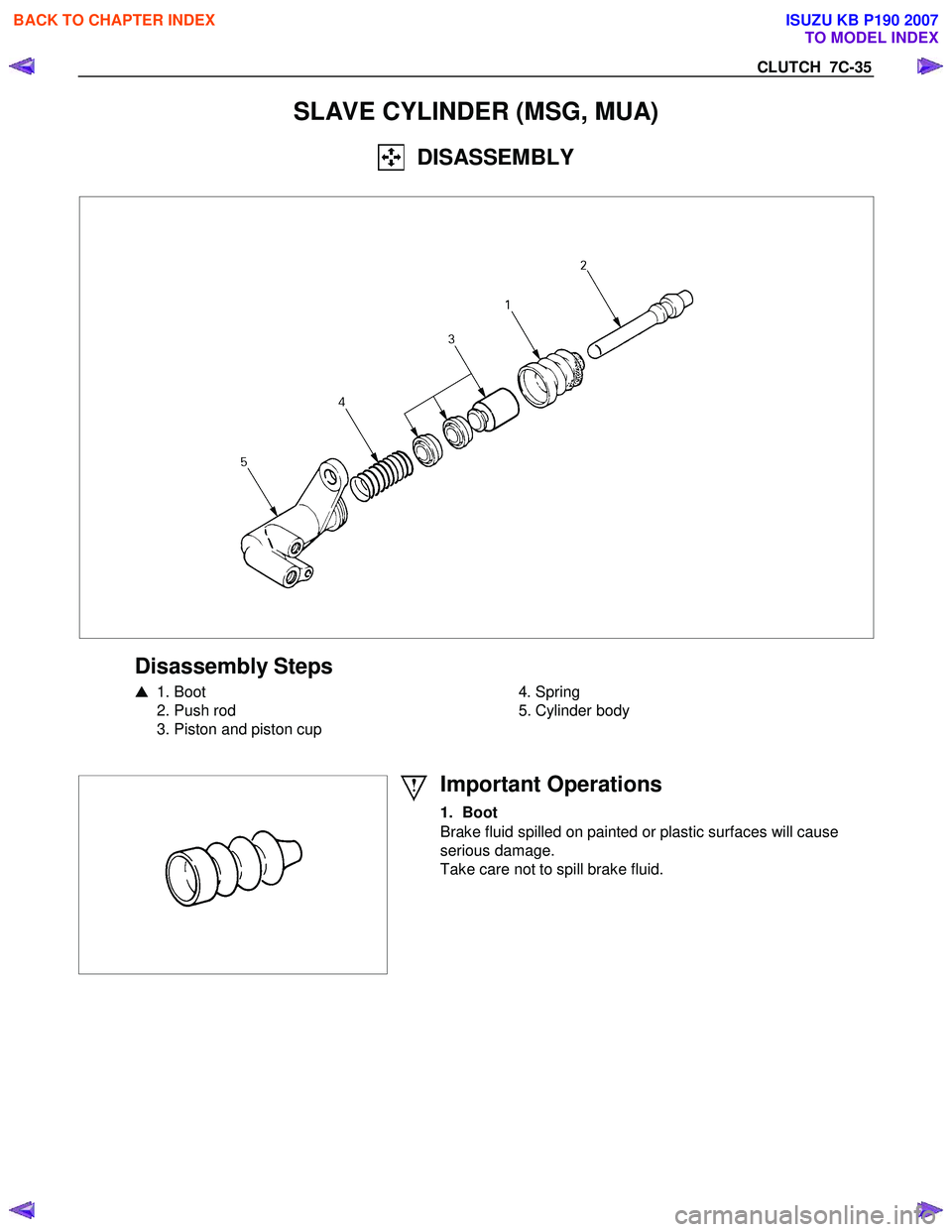
SLAVE CYLINDER (MSG, MUA)
DISASSEMBLY
Disassembly Steps
� 1. Boot
2. Push rod
3. Piston and piston cup
4. Spring
5. Cylinder body
Important Operations
1. Boot
Brake fluid spilled on painted or plastic surfaces will cause
serious damage.
Take care not to spill brake fluid.
BACK TO CHAPTER INDEX
TO MODEL INDEX
ISUZU KB P190 2007
Page 4815 of 6020
CLUTCH 7C-37
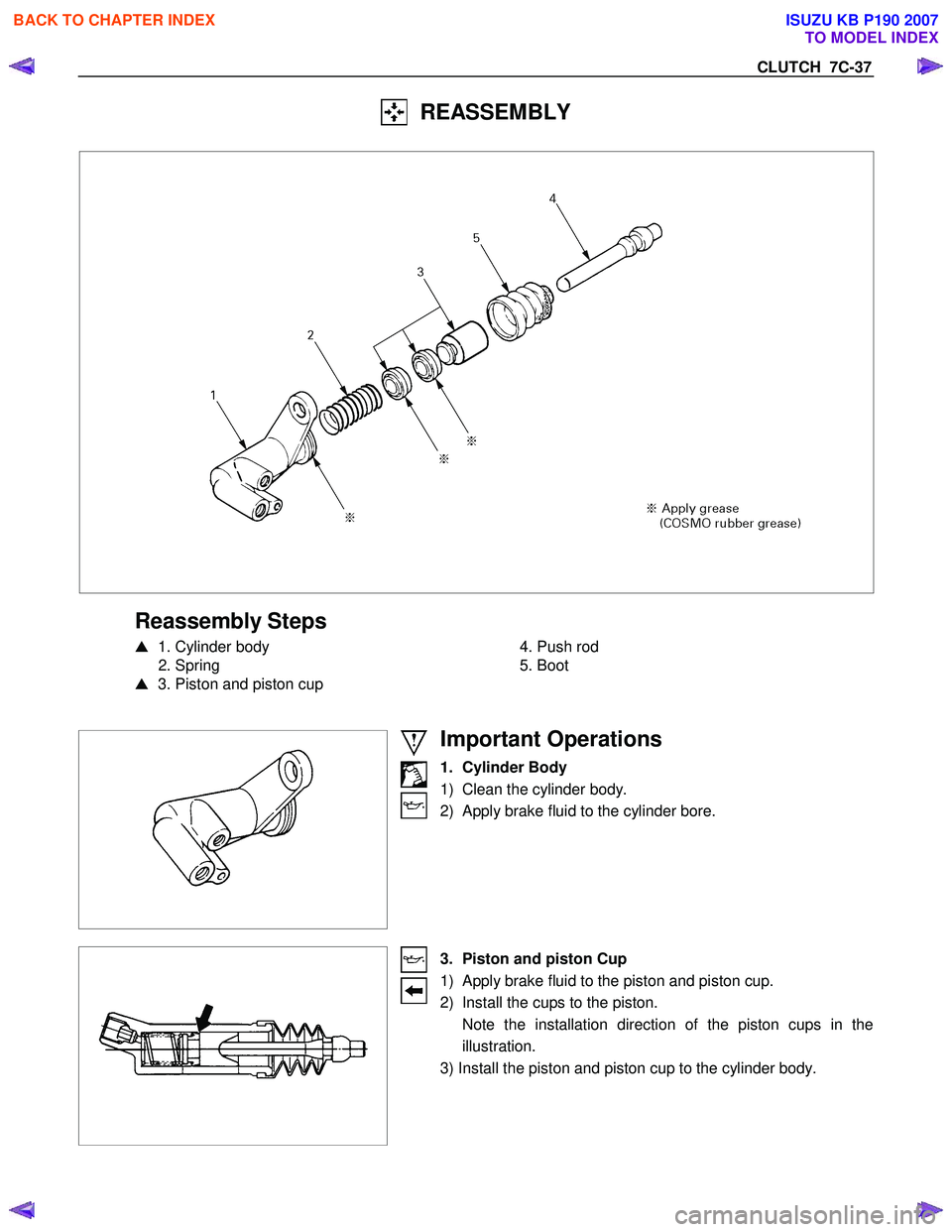
REASSEMBLY
Reassembly Steps
� 1. Cylinder body
2. Spring
� 3. Piston and piston cup
4. Push rod
5. Boot
Important Operations
1. Cylinder Body
1) Clean the cylinder body.
2) Apply brake fluid to the cylinder bore.
3. Piston and piston Cup
1) Apply brake fluid to the piston and piston cup.
2) Install the cups to the piston.
Note the installation direction of the piston cups in the illustration.
3) Install the piston and piston cup to the cylinder body.
BACK TO CHAPTER INDEX
TO MODEL INDEX
ISUZU KB P190 2007
Page 5290 of 6020

8A-352 ELECTRICAL-BODY AND CHASSIS
2. When the parking brake lever is released, the indicator light does not go off
Checkpoint Trouble Cause Countermeasure
Adjust the SW . installation
position or replace the parking
brake SW . Incorrect the parking brake
SW . adjustment or parking
brake SW . faulty
NG
Thermo unit malfunction
Replace the brake fluid level
SW ., or repair a short circuit
between the parking brake
SW . connector 1
C39,
1
R4 and 4 B23 (C24SE :
9
B23 ) or the brake fluid
level SW . connector 2
C37
and 4
B23 (C24SE : 9
B23 )
Check to see if the indicator
light goes off when the parking
brake SW . connector 1
C39
(stick type), 1
R4 (lever
type) is disconnected
Brake fluid level SW . faulty or
short circuit
NG
OK
Parking brake SW . installation
position and function
3. Oil pressure warning light does not go off while engine is running
Refer to ENGINE Section
Refer to ENGINE Section
NG Thermo unit malfunction
Check to see the warning light
goes off when the oil pressure
SW . connector
1
E1 is disconnected or
when the PIM (Oil pressure)
connector 6
B96 (HFV6) is
disconnected
Repair a short circuit between
1
E1 and 39 B23
(C24SE : 17
B24) or 6
B96 and 39 B23 (HFV6)
Short circuit
NG
OK
Replace the oil pressure SW .
Continuity between the oil
pressure SW . connector
1
E1 (HFV6 : 6 B96 )and
the body ground when the
engine is operating
Oil pressure SW . faulty
NG
OK
Engine oil pressure
BACK TO CHAPTER INDEX TO MODEL INDEXISUZU KB P190 2007