Page 459 of 6020
REAR AXLE 4B-15
Reassembly
1. Using the oil seal installer 5-8840-2202-0 and
grip 5-8840-0007-0, install new axle case oil seal.
RTW 54BSH000301
Note :
Confirm that the dimension : A should be 34.5 –
36.1 mm (1.36 – 1.42 in)
A03R300004
2. Install new oil seal in bearing holder, using the oil seal installer 5-8840-2404-0.
RTW 54BSH000501
Legend
1. Oil Seal
2. Bearing Holder
3. Drive wheel pin into axle shaft flange, using a hammer.
4. Differential assembly a. Clean the mating surface of axle case and differential carrier.
b.
Apply Three Bond 1215 (TB1215) or
equivalent on the surface of differential
assembly as flowing illustration.
RTW 74BSH000301
Legend
a. 3 mm (0.12 in)
c. Tighten bolts and nuts to the specified torque.
BACK TO CHAPTER INDEX
TO MODEL INDEX
ISUZU KB P190 2007
Page 461 of 6020

REAR AXLE 4B-17
8. Certainly install new snap ring, use snap ring
pliers. W hen transform or damage, replace ne
w
one.
RTW 34BMH000101
Legend
1. Snap ring
2. Crevice
3. Retainer (with ABS)
Retainer (without ABS)
9. Insert a shim of sufficient thickness between
snap ring and end of retainer.
Standard 0 − 0.2 mm (0 − 0.008 in)
Crevice is measured using thickness gauge, and
when crevice exceeds 0.2 mm (0.008 in), it
adjusts so that is may become 0.2 mm (0.008 in)
or less using shim.
Shim Pats No. Thickness
1 9-41519110- ∗ 0.18 mm (0.0071 in)
2 8-97130387- ∗ 0.50 mm (0.0197 in)
Crevice No. of shim Total
mm (in)
1 2 mm (in)
1.0(0.0394) 2 1.00(0.0394)
0.9(0.0354) 2 1 0.86(0.0339)
0.8(0.0315) 1 1 0.68(0.0268)
0.7(0.0276) 1 1 0.68(0.0268)
0.6(0.0236) 1 0.50(0.0197)
0.5(0.0197) 1 0.50(0.0197)
0.4(0.0157) 2 0.36(0.0142)
0.3(0.0118) 1 0.18(0.0071)
0.2(0.0079) 1 0.18(0.0071)
10. Install axle shaft assembly in rear axle case
assembly.
a. Clean the mating surface of axle case and bearing holder.
b. Apply Three Bond 1215 (TB1215) o
r
equivalent on the surface of axle case
assembly.
Note:
When inserting an axle shaft, it inserts so that an
oil seal may not be damaged.
11. Install and tighten bearing holder fixing nut to the specified torque.
Torque : 84 N ⋅m (8.6 kgf ⋅m/62 lb ⋅ft)
12. Install wheel cylinder and tighten the bolt to the specified torque.
Torque : 9 N ⋅m (0.9 kgf ⋅m/78 lb ⋅in)
13. Install parking brake outer cable in back plate and inner cable in parking brake lever.
BACK TO CHAPTER INDEX
TO MODEL INDEX
ISUZU KB P190 2007
Page 463 of 6020
REAR AXLE 4B-19
17. Install brake pipe and ABS sensor and tighten it
to the specified torque.
Torque : ABS Sensor 8 N ⋅m (0.8 kgf ⋅m/69 lb ⋅in)
Brake Pipe 16 N ⋅m (1.6 kgf ⋅m/12 lb ⋅ft)
420R30003
18. Bleed brake pipe at the wheel cylinder. (Refer to
the section “Power-assisted Brake System”)
19. Install brake drum.
• Install propeller shaft. (Refer to Section “Rea
r
Propeller Shaft”.)
• Refill differential oil.
• Install wheel and tire.
• Lower vehicle.
BACK TO CHAPTER INDEX
TO MODEL INDEX
ISUZU KB P190 2007
Page 499 of 6020
REAR AXLE 4B-55
4. POWER NOT BEING TRANSMITTED TO THE WHEELS
(PROPELLER SHAFT OPERATION IS NORMAL)
Checkpoint Trouble Cause Countermeasure
Replace the rear axle shaftBroken rear axle shaft
NG
Replace the drive pinion and
the ring gear as a setDrive pinion and ring gearBroken drive pinion and/or ring
gear
Replace the differential gears
and/or the spiderDifferential cage gearsBroken differential cage gears
and/or spider
NG
NG
OK
OK
Rear axle shaft
BACK TO CHAPTER INDEX
TO MODEL INDEX
ISUZU KB P190 2007
Page 505 of 6020

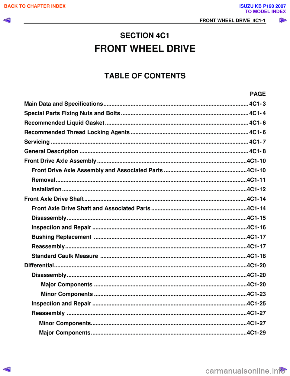
FRONT WHEEL DRIVE 4C1-1
SECTION 4C1
FRONT WHEEL DRIVE
TABLE OF CONTENTS
PAGE
Main Data and Specifications ........................................................................................... 4C1- 3
Special Parts Fixing Nuts and Bolts ................................................................................ 4C1- 4
Recommended Liquid Gasket .......................................................................................... 4C1- 6
Recommended Thread Locking Agents .......................................................................... 4C1- 6
Servicing ...................................................................................................................... ...... 4C1- 7
General Description .......................................................................................................... 4C 1- 8
Front Drive Axle Assembly ..............................................................................................4C1- 10 Front Drive Axle Assembly and Associated Parts ....................................................4C1- 10
Removal ........................................................................................................................ 4C1- 11
Installation ................................................................................................................... .4C1- 12
Front Axle Drive Shaft ......................................................................................................4C1 - 14
Front Axle Drive Shaft and Associated Parts ............................................................4C1- 14
Disassembly .................................................................................................................4C1 - 15
Inspection and Repair .................................................................................................4C1- 16
Bushing Replacement ................................................................................................4C1- 17
Reassembly ..................................................................................................................4C1 - 17
Standard Caulk Measure ............................................................................................4C1- 18
Differential................................................................................................................... ......4C1- 20
Disassembly .................................................................................................................4C1 - 20
Major Components ................................................................................................4C1- 20
Minor Components ................................................................................................4C1- 23
Inspection and Repair .................................................................................................4C1- 25
Reassembly .................................................................................................................4C1 - 27
Minor Components..................................................................................................4C1- 27
Major Components ..................................................................................................4C1- 29
BACK TO CHAPTER INDEX
TO MODEL INDEX
ISUZU KB P190 2007
Page 506 of 6020

4C1-2 FRONT WHEEL DRIVE
PAGE
Front Hub and Disc (4×2 Except High Ride Suspension Model) ..................................4C1- 38 Disassembly .................................................................................................................4C1 - 38
Inspection and Repair .................................................................................................4C1- 41
Reassembly ..................................................................................................................4C1 - 42
Front Hub and Disc
(4×4, 4×2 High Ride Suspension, 4×4 Rigid Hub, 4×4 Shift On the Fly Model) ..........4C1- 46 Disassembly .................................................................................................................4C1 - 46
Inspection and Repair .................................................................................................4C1- 48
Reassembly ..................................................................................................................4C1 - 49
Front Hub and Disc (4×4 Manual Locking Hub Model)..................................................4C1- 53 Disassembly .................................................................................................................4C1 - 53
Inspection and Repair .................................................................................................4C1- 56
Reassembly ..................................................................................................................4C1 -57
Troubleshooting ...............................................................................................................4 C1-63
Special Service Tool.........................................................................................................4C 1-71
BACK TO CHAPTER INDEX
TO MODEL INDEX
ISUZU KB P190 2007
Page 507 of 6020
FRONT WHEEL DRIVE 4C1-3
MAIN DATA AND SPECIFICATIONS
FRONT AXLE AND DIFFERENTIAL
Ring gear size mm (in) φ
φφ
φ
194 (7.6)
Axle tube
Type It consists of the duce, a cast iron housing and the Axle tube.
Gear type Hypoid
Gear ratio (to 1) 3.583, 3.727, 3.909, 4.100, 4.300, 4.555, 4.777, 5.125
Differential type Two pinion
Specified gear oil (APL grade) GL-5
Oil capacity liter 1.4
(US/UK gal.) (0.4/0.31)
Axle shaft type Constant velocity joint (Barfield joint type and double offset joint).
BACK TO CHAPTER INDEX
TO MODEL INDEX
ISUZU KB P190 2007
Page 508 of 6020
4C1-4 FRONT WHEEL DRIVE
SPECIAL PARTS FIXING NUTS AND BOLTS
FRONT DRIVE AXLE AND PROPELLER SHAFT
N⋅m (kgf ⋅m/lb ⋅ft)
RTW 74CMF000101
BACK TO CHAPTER INDEX
TO MODEL INDEX
ISUZU KB P190 2007