Page 4848 of 6020
7D-18 TRANSFER CASE
Transfer Disassembly
RTW 67DLF000101
Legend
(1) Transfer Case Speedometer Bushing, Plate and Driven Gear
(2) Companion Flange, O-ring and Nut
(8)
(M/T: MUA, MUX, A/T: JR405E, AW 30-40LE)
(3) Stoneguard (9) Speed sensor (M/T: AR-5, A/T: 4L60-E)
(4) Detent Plug, Spring and Detent Ball (10) Transfer Actuator (Diesel Engine)
(5) 2-4 Switch ASM (11) Transfer Actuator (Gasoline Engine)
(6) Switch Bracket (12) Breather Hose
(7) Neutral Switch ASM (13) Heat Protector (Gasoline Engine)
Removal
1. Remove the stoneguard.
2. Remove the drain plug from the transfer case to drain
the oil.
3. Remove the parts listed below.
• Speedometer bushing, plate, and speedomete
r
driven gear (M/T: MUA, MUX, A/T: JR405E,
AW 30-40LE)
• Speed sensor (M/T: AR-5, A/T: 4L60-E)
BACK TO CHAPTER INDEX
TO MODEL INDEX
ISUZU KB P190 2007
Page 4868 of 6020
7D-38 TRANSFER CASE
226R300011
36. Install the rear cover to the transfer case and tighten
the bolts to the specified torque.
Rear cover and transfer case bolt torque:
22 N ·m (2.2 kgf ·m/16 lb ·ft)
37. Apply engine oil to the companion flange O-ring.
38. Install the O-ring to the front output shaft.
39. Secure the front companion flange with a flange
holder (5-8840-0133-0).
40. Install the end nuts and tighten them to the specified
torque.
Front companion flange end nut torque:
137 N ·m (14.0 kgf ·m/101 lb ·ft)
RTW 77DSH000201
41. Use a punch (5-8840-2293-0) to caulk the front
companion flange end nut.
226R300012
RUW 34DSH000301
Legend
(1) MAX 26mm (1.02 in)
(2) MIN 4mm (0.16 in)
42.
Apply Loctite 575 to the threaded portion of the
detente plugs.
BACK TO CHAPTER INDEX
TO MODEL INDEX
ISUZU KB P190 2007
Page 4963 of 6020

ELECTRICAL-BODY AND CHASSIS 8A-25
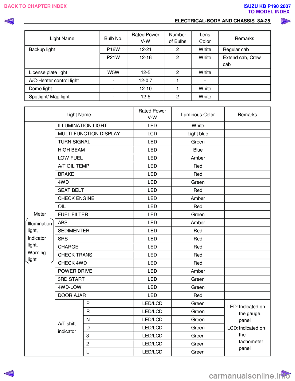
Light Name Bulb No. Rated Power
V-W Number
of Bulbs Lens
Color Remarks
P16W 12-21 2 W hite Regular cab Backup light
P21W 12-16 2 W hite Extend cab, Crew cab
License plate light W 5W 12-5 2 W hite
A/C-Heater control light - 12-0.7 1 -
Dome light - 12-10 1 W hite
Spotlight/ Map light - 12-5 2 W hite
Light Name Rated Power
V-W Luminous Color Remarks
ILLUMINATION
LIGHT LED W hite
MULTI FUNCTION DISPLAY LCD Light blue
TURN SIGNAL LED Green
HIGH BEAM LED Blue
LOW FUEL LED Amber
A/T OIL TEMP LED Red
BRAKE LED Red
4W D LED Green
SEAT BELT LED Red
CHECK ENGINE LED Amber
OIL LED Red
FUEL FILTER LED Green
ABS LED Amber
SEDIMENTER LED Red
SRS LED Red
CHARGE LED Red
CHECK TRANS LED Red
CHECK 4W D LED Red
POW ER DRIVE LED Amber
3RD START LED Green
4W D-LOW LED Green
DOOR AJAR LED Red
P LED/LCD Green
R LED/LCD Green
N LED/LCD Green
D LED/LCD Green
3 LED/LCD Green
2 LED/LCD Green
A/T shift
indicator
L LED/LCD Green LED: Indicated on
the gauge
panel
LCD: Indicated on the
tachometer
panel
Meter
Illumination
light,
Indicator
light,
W arning
light
BACK TO CHAPTER INDEX TO MODEL INDEXISUZU KB P190 2007
Page 4971 of 6020
ELECTRICAL-BODY AND CHASSIS 8A-33
FUSE LOCATION
RHD/LHD
FUSE
NO. Capacity Indication on label NO. Capacity Indication on label
C 1 10A STARTER C 1110A AUDIO
C2
C
12 20A CIGAR/ACC SOCKET
10A TRAILER *3 C 13 15A AUDIO (+B)
C3 10A ELEC IG C 14 10A METER
C4 10A TURN C 15 15A STOP
C5 10A ABS/4WD C 16
C6 10A ENGINE C 17 10A ROOM
10A ECU *4 C19 10A METER (+B)
C7 15A TCM/IG COIL/ C2 120A DOOR LOCK
10A GLOW ENGINE *4 C22
C8 10A SRS 10A ANTI THEFT *5
C9 20A FRT WIPER
C10 15A BACKUP
SLOW BLOW FUSE
NO. Capacity Indication on label
C 18 20A RR DEF
C20 30A POWER WINDOW
FUSE BOX
*3 … HFV6 (AUSTRALIA)
*4 … HFV6
*5 … 4JJ 1-TC (EUROPE)
BACK TO CHAPTER INDEX
TO MODEL INDEXISUZU KB P190 2007
Page 5290 of 6020

8A-352 ELECTRICAL-BODY AND CHASSIS
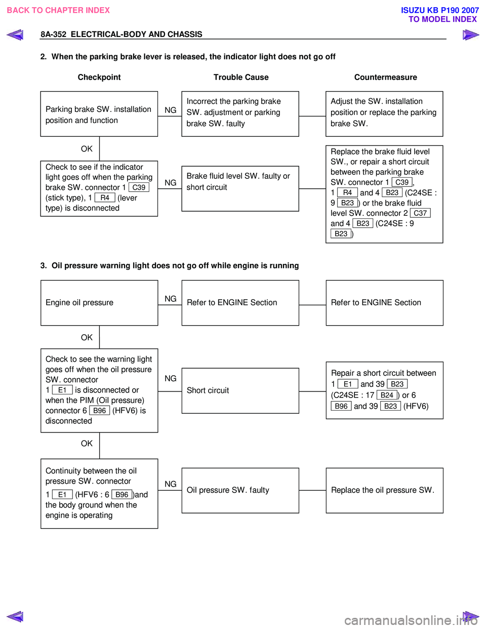
2. When the parking brake lever is released, the indicator light does not go off
Checkpoint Trouble Cause Countermeasure
Adjust the SW . installation
position or replace the parking
brake SW . Incorrect the parking brake
SW . adjustment or parking
brake SW . faulty
NG
Thermo unit malfunction
Replace the brake fluid level
SW ., or repair a short circuit
between the parking brake
SW . connector 1
C39,
1
R4 and 4 B23 (C24SE :
9
B23 ) or the brake fluid
level SW . connector 2
C37
and 4
B23 (C24SE : 9
B23 )
Check to see if the indicator
light goes off when the parking
brake SW . connector 1
C39
(stick type), 1
R4 (lever
type) is disconnected
Brake fluid level SW . faulty or
short circuit
NG
OK
Parking brake SW . installation
position and function
3. Oil pressure warning light does not go off while engine is running
Refer to ENGINE Section
Refer to ENGINE Section
NG Thermo unit malfunction
Check to see the warning light
goes off when the oil pressure
SW . connector
1
E1 is disconnected or
when the PIM (Oil pressure)
connector 6
B96 (HFV6) is
disconnected
Repair a short circuit between
1
E1 and 39 B23
(C24SE : 17
B24) or 6
B96 and 39 B23 (HFV6)
Short circuit
NG
OK
Replace the oil pressure SW .
Continuity between the oil
pressure SW . connector
1
E1 (HFV6 : 6 B96 )and
the body ground when the
engine is operating
Oil pressure SW . faulty
NG
OK
Engine oil pressure
BACK TO CHAPTER INDEX TO MODEL INDEXISUZU KB P190 2007
Page 5303 of 6020

ELECTRICAL-BODY AND CHASSIS 8A-365
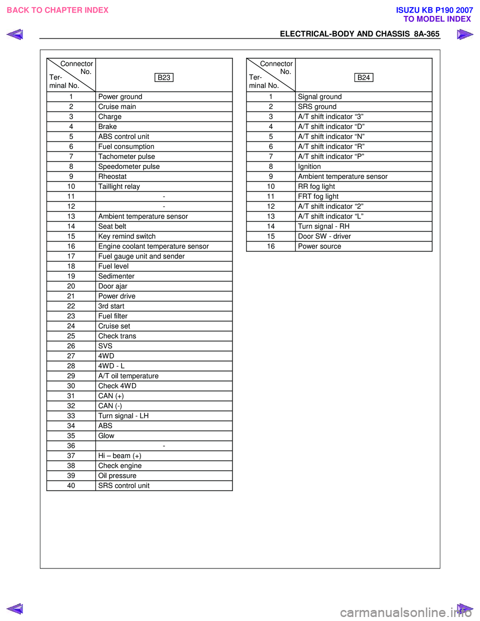
Connector
Ter- No.
minal No.
B23
1 Power ground
2 Cruise main
3 Charge
4 Brake
5 ABS control unit
6 Fuel consumption
7 Tachometer pulse
8 Speedometer pulse
9 Rheostat
10 Taillight relay
11 -
12 -
13 Ambient temperature sensor
14 Seat belt
15 Key remind switch
16 Engine coolant temperature sensor
17 Fuel gauge unit and sender
18 Fuel level
19 Sedimenter
20 Door ajar
21 Power drive
22 3rd start
23 Fuel filter
24 Cruise set
25 Check trans
26 SVS
27 4W D
28 4W D - L
29 A/T oil temperature
30 Check 4W D
31 CAN (+)
32 CAN (-)
33 Turn signal - LH
34 ABS
35 Glow
36 -
37 Hi – beam (+)
38 Check engine
39 Oil pressure
40 SRS control unit
Connector
Ter- No.
minal No.
B24
1 Signal ground
2 SRS ground
3 A/T shift indicator “3”
4 A/T shift indicator “D”
5 A/T shift indicator “N”
6 A/T shift indicator “R”
7 A/T shift indicator “P”
8 Ignition
9 Ambient temperature sensor
10 RR fog light
11 FRT fog light
12 A/T shift indicator “2”
13 A/T shift indicator “L”
14 Turn signal - RH
15 Door SW - driver
16 Power source
BACK TO CHAPTER INDEX TO MODEL INDEXISUZU KB P190 2007
Page 5304 of 6020

8A-366 ELECTRICAL-BODY AND CHASSIS
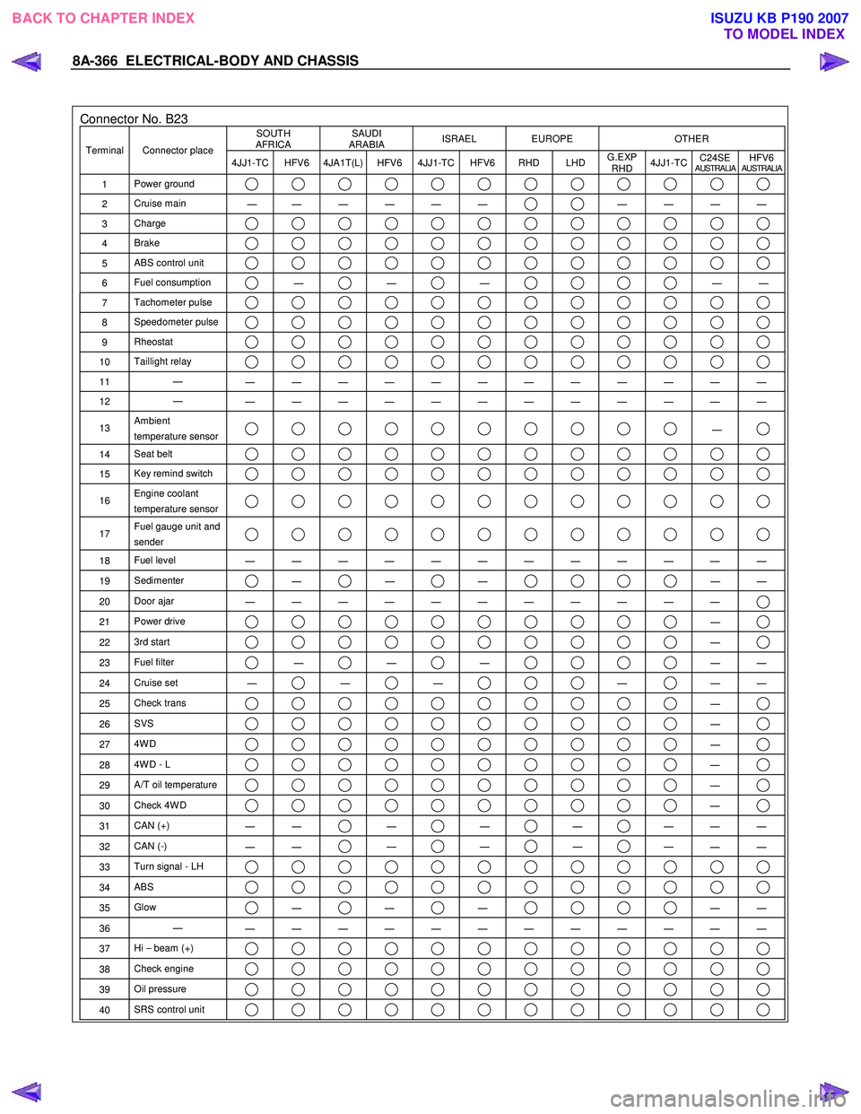
Connector No. B23 SOUTH
AFRICA SAUDI
ARABIA ISRAEL EUROPE OTHER
Terminal Connector place
4JJ1-TC HFV6 4JA1T(L) HFV6 4JJ1-TC HFV6 RHD LHD G.EXP
RHD 4JJ1-TC
C24SE
AUSTRALIAHFV6AUSTRALIA
1
Power ground
2 Cruise main
―
― ― ― ― ― ― ― ― ―
3
Charge
4 Brake
5 ABS control unit
6 Fuel consumption ―
―
―
―
―
7 Tachometer pulse
8 Speedometer pulse
9 Rheostat
10 Taillight relay
11 ―
― ― ― ― ― ― ― ― ― ― ― ―
12 ―
― ― ― ― ― ― ― ― ― ― ― ―
13 Ambient
temperature sensor ―
14 Seat belt
15 Key remind switch
16 Engine coolant
temperature sensor
17 Fuel gauge unit and
sender
18 Fuel level
― ― ― ― ― ― ― ― ― ― ― ―
19 Sedimenter ―
―
―
―
―
20 Door ajar
― ― ― ― ― ― ― ― ― ― ―
21 Power drive ―
22 3rd start ―
23 Fuel filter ―
―
―
―
―
24 Cruise set
― ―
―
―
―
―
25 Check trans ―
26 SVS ―
27 4W D ―
28 4W D - L ―
29 A/T oil temperature ―
30 Check 4W D ―
31 CAN (+)
― ― ―
―
―
― ― ―
32
CAN (-)
― ― ―
―
―
― ― ―
33
Turn signal - LH
34 ABS
35 Glow ―
―
―
―
―
36 ―
― ― ― ― ― ― ― ― ― ― ― ―
37 Hi – beam (+)
38 Check engine
39 Oil pressure
40 SRS control unit
BACK TO CHAPTER INDEX
TO MODEL INDEXISUZU KB P190 2007
Page 5557 of 6020
ELECTRICAL-BODY AND CHASSIS 8A-619
No. Connector face No. Connector face
E1
Gray
Oil pressure switch E9
Gray
T.D.C sensor
E2
(C24SE)
Magnetic clutch E10
SilverEngine ground
E3
Black
Magnetic clutch AC COMP E11
Natural greenNeutral switch
E4
Green
Generator E12
Natural greenNeutral switch
E5
TPS EGR E13
Gray Injector nozzle 1
E6
(C24SE)
Fuel injector (C24SE) E14
Gray
Injector nozzle 2
E6
Injector pump E15
Gray Injector nozzle 3
E7
(C24SE)
Fuel injector (C24SE) E16
Gray
Injector nozzle 4
E8
(C24SE)
Fuel injector (C24SE) E17
Silver
Generator (B)
E9
(C24SE)
Fuel injector (C24SE) E18
(C24SE)
Ignition coil
BACK TO CHAPTER INDEX TO MODEL INDEXISUZU KB P190 2007