2007 ISUZU KB P190 service
[x] Cancel search: servicePage 5693 of 6020
RESTRAINT CONTROL SYSTEM 9A1-11
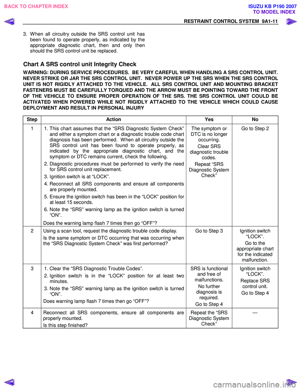
3. W hen all circuitry outside the SRS control unit has been found to operate properly, as indicated by the
appropriate diagnostic chart, then and only then
should the SRS control unit be replaced.
Chart A SRS control unit Integrity Check
WARNING: DURING SERVICE PROCEDURES. BE VERY CAREFUL WHEN HANDLING A SRS CONTROL UNIT.
NEVER STRIKE OR JAR THE SRS CONTROL UNIT. NEVER POWER UP THE SRS WHEN THE SRS CONTROL
UNIT IS NOT RIGIDLY ATTACHED TO THE VEHICLE. ALL SRS CONTROL UNIT AND MOUNTING BRACKET
FASTENERS MUST BE CAREFULLY TORQUED AND THE ARROW MUST BE POINTING TOWARD THE FRONT
OF THE VEHICLE TO ENSURE PROPER OPERATION OF THE SRS. THE SRS CONTROL UNIT COULD BE
ACTIVATED WHEN POWERED WHILE NOT RIGIDLY ATTACHED TO THE VEHICLE WHICH COULD CAUSE
DEPLOYMENT AND RESULT IN PERSONAL INJURY
Step Action Yes No
1 1. This chart assumes that the “SRS Diagnostic System Check”
and either a symptom chart or a diagnostic trouble code chart
diagnosis has been performed. W hen all circuitry outside the
SRS control unit has been found to operate properly, as
indicated by the appropriate diagnostic chart, and the
symptom or DTC remains current, check the following.
2. Diagnostic procedures must be performed to verify the need
for SRS control unit replacement.
3. Ignition switch is at “LOCK”.
4. Reconnect all SRS components and ensure all components are properly mounted.
5. Ensure the ignition switch has been in the “LOCK” position for
at least 15 seconds.
6. Note the “SRS” warning lamp as the ignition switch is turned
“ON”.
Does the warning lamp flash 7 times then go “OFF”? The symptom or
DTC is no longer occurring.
Clear SRS
diagnostic trouble codes.
Repeat “SRS
Diagnostic System Check” Go to Step 2
2 Using a scan tool, request the diagnostic trouble code display.
Is the same symptom or DTC occurring that was occurring when
the “SRS Diagnostic System Check” was first performed? Go to Step 3 Ignition switch
“LOCK”.
Go to the
appropriate chart for the indicated malfunction.
3 1. Clear the “SRS Diagnostic Trouble Codes”.
2. Ignition switch is in the “LOCK” position for at least two
minutes.
3. Note the “SRS” warning lamp as the ignition switch is turned
“ON”.
Does warning lamp flash 7 times then go “OFF”? SRS is functional
and free of
malfunctions.
No further
diagnosis is required.
Go to Step 4 Ignition switch
“LOCK”.
Replace SRS control unit.
Go to Step 4
4 Reconnect all SRS components, ensure all components are properly mounted.
Is this step finished? Repeat the “SRS
Diagnostic System Check” —
BACK TO CHAPTER INDEX
TO MODEL INDEX
ISUZU KB P190 2007
Page 5697 of 6020
RESTRAINT CONTROL SYSTEM 9A1-15
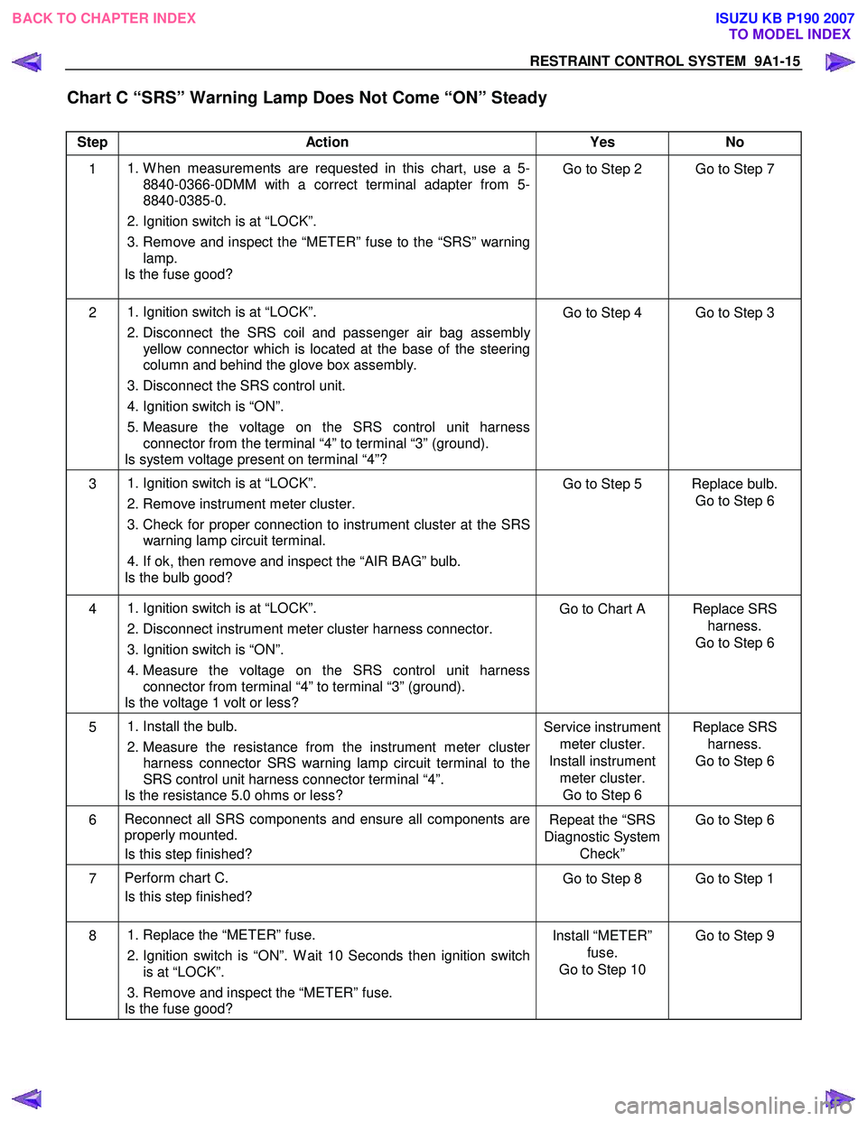
Chart C “SRS” Warning Lamp Does Not Come “ON” Steady
Step Action Yes No
1
1. W hen measurements are requested in this chart, use a 5-
8840-0366-0DMM with a correct terminal adapter from 5-
8840-0385-0.
2. Ignition switch is at “LOCK”.
3. Remove and inspect the “METER” fuse to the “SRS” warning lamp.
Is the fuse good? Go to Step 2 Go to Step 7
2
1. Ignition switch is at “LOCK”.
2. Disconnect the SRS coil and passenger air bag assembly
yellow connector which is located at the base of the steering
column and behind the glove box assembly.
3. Disconnect the SRS control unit.
4. Ignition switch is “ON”.
5. Measure the voltage on the SRS control unit harness connector from the terminal “4” to terminal “3” (ground).
Is system voltage present on terminal “4”? Go to Step 4 Go to Step 3
3
1. Ignition switch is at “LOCK”.
2. Remove instrument meter cluster.
3. Check for proper connection to instrument cluster at the SRS warning lamp circuit terminal.
4. If ok, then remove and inspect the “AIR BAG” bulb.
Is the bulb good? Go to Step 5 Replace bulb.
Go to Step 6
4
1. Ignition switch is at “LOCK”.
2. Disconnect instrument meter cluster harness connector.
3. Ignition switch is “ON”.
4. Measure the voltage on the SRS control unit harness
connector from terminal “4” to terminal “3” (ground).
Is the voltage 1 volt or less? Go to Chart A Replace SRS
harness.
Go to Step 6
5
1. Install the bulb.
2. Measure the resistance from the instrument meter cluster
harness connector SRS warning lamp circuit terminal to the
SRS control unit harness connector terminal “4”.
Is the resistance 5.0 ohms or less? Service instrument
meter cluster.
Install instrument meter cluster. Go to Step 6 Replace SRS
harness.
Go to Step 6
6 Reconnect all SRS components and ensure all components are
properly mounted.
Is this step finished? Repeat the “SRS
Diagnostic System Check” Go to Step 6
7
Perform chart C.
Is this step finished? Go to Step 8 Go to Step 1
8
1. Replace the “METER” fuse.
2. Ignition switch is “ON”. W ait 10 Seconds then ignition switch
is at “LOCK”.
3. Remove and inspect the “METER” fuse.
Is the fuse good? Install “METER”
fuse.
Go to Step 10 Go to Step 9
BACK TO CHAPTER INDEX
TO MODEL INDEX
ISUZU KB P190 2007
Page 5745 of 6020
RESTRAINT CONTROL SYSTEM 9A1-63
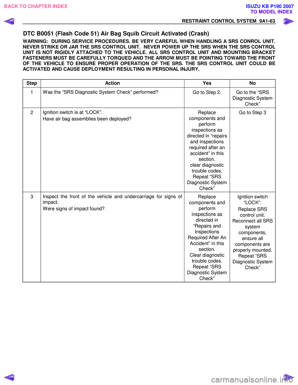
DTC B0051 (Flash Code 51) Air Bag Squib Circuit Activated (Crash)
WARNING: DURING SERVICE PROCEDURES. BE VERY CAREFUL WHEN HANDLING A SRS CONROL UNIT.
NEVER STRIKE OR JAR THE SRS CONTROL UNIT. NEVER POWER UP THE SRS WHEN THE SRS CONTROL
UNIT IS NOT RIGIDLY ATTACHED TO THE VEHICLE. ALL SRS CONTROL UNIT AND MOUNTING BRACKET
FASTENERS MUST BE CAREFULLY TORQUED AND THE ARROW MUST BE POINTING TOWARD THE FRONT
OF THE VEHICLE TO ENSURE PROPER OPERATION OF THE SRS. THE SRS CONTROL UNIT COULD BE
ACTIVATED AND CAUSE DEPLOYMENT RESULTING IN PERSONAL INJURY.
Step Action Yes No
1 W as the “SRS Diagnostic System Check” performed?
Go to Step 2. Go to the “SRS
Diagnostic System Check”
2 Ignition switch is at “LOCK”.
Have air bag assemblies been deployed? Replace
components and perform
inspections as
directed in “repairs and inspections
required after an accident” in this section.
clear diagnostic trouble codes. Repeat “SRS
Diagnostic System Check” Go to Step 3
3
Inspect the front of the vehicle and undercarriage for signs of
impact.
W ere signs of impact found? Replace
components and perform
inspections as directed in
“Repairs and Inspections
Required After An Accident” in this section.
Clear diagnostic trouble codes. Repeat “SRS
Diagnostic System Check” Ignition switch
“LOCK”.
Replace SRS control unit.
Reconnect all SRS system
components, ensure all
components are
properly mounted. Repeat “SRS
Diagnostic System Check”
BACK TO CHAPTER INDEX TO MODEL INDEX
ISUZU KB P190 2007
Page 5747 of 6020
RESTRAINT CONTROL SYSTEM 9A1-65
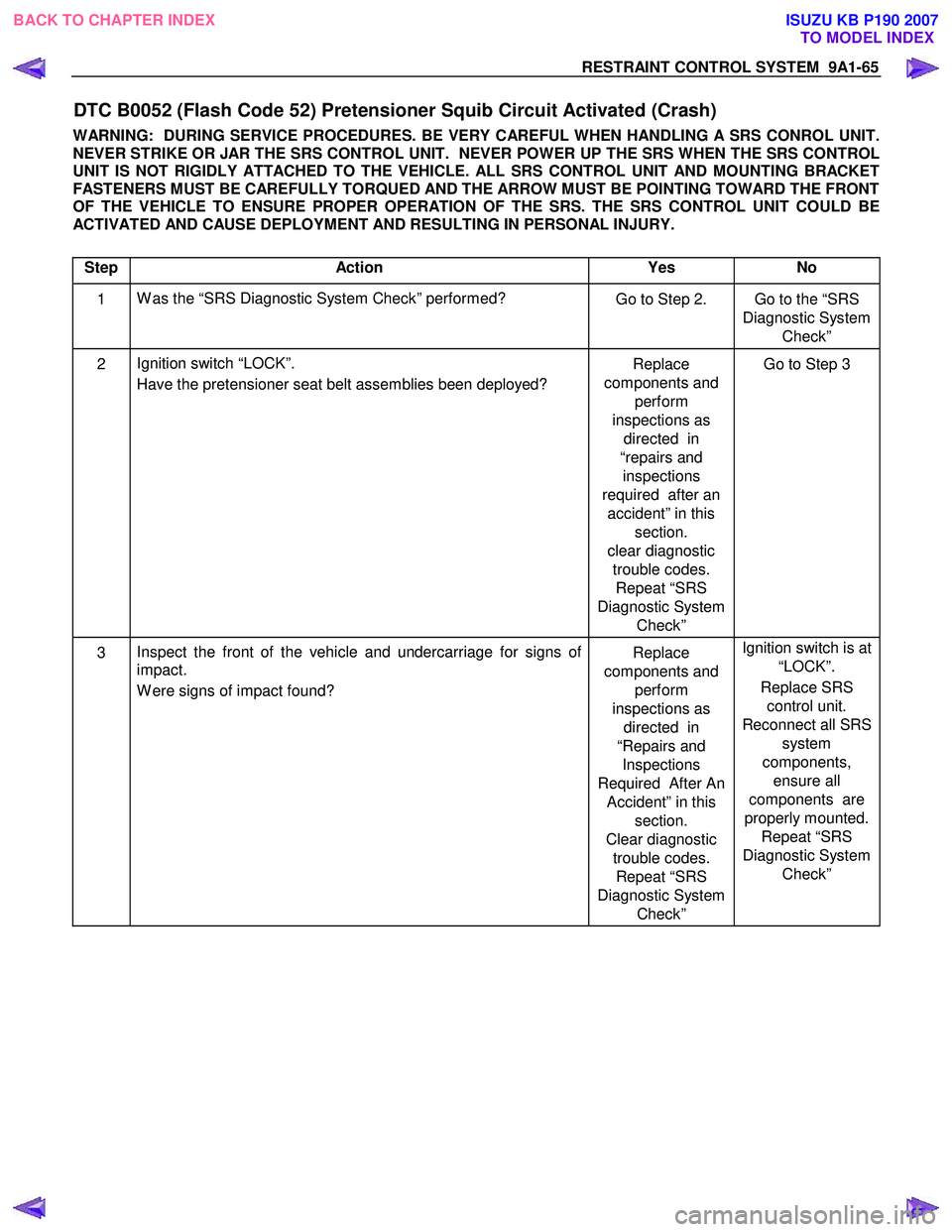
DTC B0052 (Flash Code 52) Pretensioner Squib Circuit Activated (Crash)
WARNING: DURING SERVICE PROCEDURES. BE VERY CAREFUL WHEN HANDLING A SRS CONROL UNIT.
NEVER STRIKE OR JAR THE SRS CONTROL UNIT. NEVER POWER UP THE SRS WHEN THE SRS CONTROL
UNIT IS NOT RIGIDLY ATTACHED TO THE VEHICLE. ALL SRS CONTROL UNIT AND MOUNTING BRACKET
FASTENERS MUST BE CAREFULLY TORQUED AND THE ARROW MUST BE POINTING TOWARD THE FRONT
OF THE VEHICLE TO ENSURE PROPER OPERATION OF THE SRS. THE SRS CONTROL UNIT COULD BE
ACTIVATED AND CAUSE DEPLOYMENT AND RESULTING IN PERSONAL INJURY.
Step Action Yes No
1 W as the “SRS Diagnostic System Check” performed?
Go to Step 2. Go to the “SRS
Diagnostic System Check”
2 Ignition switch “LOCK”.
Have the pretensioner seat belt assemblies been deployed? Replace
components and perform
inspections as directed in
“repairs and inspections
required after an accident” in this section.
clear diagnostic trouble codes. Repeat “SRS
Diagnostic System Check” Go to Step 3
3
Inspect the front of the vehicle and undercarriage for signs of
impact.
W ere signs of impact found? Replace
components and perform
inspections as directed in
“Repairs and Inspections
Required After An Accident” in this section.
Clear diagnostic trouble codes. Repeat “SRS
Diagnostic System Check” Ignition switch is at
“LOCK”.
Replace SRS control unit.
Reconnect all SRS system
components, ensure all
components are
properly mounted. Repeat “SRS
Diagnostic System Check”
BACK TO CHAPTER INDEX TO MODEL INDEX
ISUZU KB P190 2007
Page 5751 of 6020
RESTRAINT CONTROL SYSTEM 9A1-69
DTC Will Clear When
The malfunction is no longer occurring and the ignition
is turned to “LOCK”.
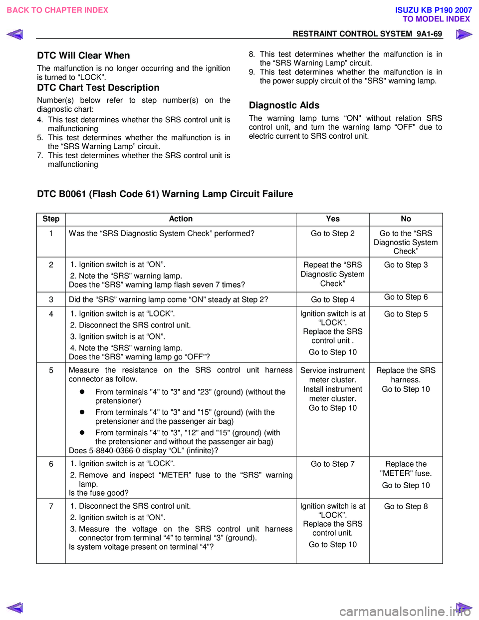
DTC Chart Test Description
Number(s) below refer to step number(s) on the
diagnostic chart:
4. This test determines whether the SRS control unit is malfunctioning
5. This test determines whether the malfunction is in the “SRS W arning Lamp” circuit.
7. This test determines whether the SRS control unit is malfunctioning
8. This test determines whether the malfunction is in
the “SRS W arning Lamp” circuit.
9. This test determines whether the malfunction is in the power supply circuit of the "SRS" warning lamp.
Diagnostic Aids
The warning lamp turns “ON" without relation SRS
control unit, and turn the warning lamp “OFF" due to
electric current to SRS control unit.
DTC B0061 (Flash Code 61) Warning Lamp Circuit Failure
Step Action Yes No
1 W as the “SRS Diagnostic System Check” performed? Go to Step 2 Go to the “SRS
Diagnostic System Check”
2
1. Ignition switch is at “ON”.
2. Note the “SRS” warning lamp.
Does the “SRS” warning lamp flash seven 7 times? Repeat the “SRS
Diagnostic System Check” Go to Step 3
3 Did the “SRS” warning lamp come “ON” steady at Step 2? Go to Step 4
Go to Step 6
4
1. Ignition switch is at “LOCK”.
2. Disconnect the SRS control unit.
3. Ignition switch is at “ON”.
4. Note the “SRS” warning lamp.
Does the “SRS” warning lamp go “OFF”? Ignition switch is at
“LOCK”.
Replace the SRS control unit .
Go to Step 10 Go to Step 5
5
Measure the resistance on the SRS control unit harness
connector as follow.
�z From terminals "4" to "3" and "23" (ground) (without the
pretensioner)
�z From terminals "4" to "3" and "15" (ground) (with the
pretensioner and the passenger air bag)
�z From terminals "4" to "3", "12" and "15" (ground) (with
the pretensioner and without the passenger air bag)
Does 5-8840-0366-0 display “OL” (infinite)? Service instrument
meter cluster.
Install instrument meter cluster.
Go to Step 10 Replace the SRS
harness.
Go to Step 10
6
1. Ignition switch is at “LOCK”.
2. Remove and inspect “METER” fuse to the “SRS” warning lamp.
Is the fuse good? Go to Step 7 Replace the
"METER" fuse.
Go to Step 10
7 1. Disconnect the SRS control unit.
2. Ignition switch is at “ON”.
3. Measure the voltage on the SRS control unit harness connector from terminal “4” to terminal “3” (ground).
Is system voltage present on terminal “4”? Ignition switch is at
“LOCK”.
Replace the SRS control unit.
Go to Step 10
Go to Step 8
BACK TO CHAPTER INDEX
TO MODEL INDEX
ISUZU KB P190 2007
Page 5752 of 6020

9A1-70 RESTRAINT CONTROL SYSTEM
Step Action Yes No
8 1. Ignition switch is at “LOCK”.
2. Measure the resistance from the instrument meter cluster harness connector "SRS" warning lamp circuit terminal to the
SRS control unit harness connector terminal “4”.
Is the resistance 5.0 ohms or less? Go to Step 9 Replace the SRS
harness.
Go to Step 10
9 1. Disconnect the instrument meter cluster harness connector.
2. Measure the resistance from the "METER" fuse to the instrument meter cluster harness connector "SRS" warning
lamp power supply circuit terminal.
Is the resistance 5.0 ohms or less? Service instrument
meter cluster.
Install instrument meter cluster.
Go to Step 10 Replace the "SRS"
warning lamp power supply
circuit harness.
Go to Step 10
10 1. Reconnect all components and ensure all components are
properly mounted.
2. Clear the diagnostic trouble codes.
Is this step finished? Go to the “SRS
Diagnostic System Check” ―
BACK TO CHAPTER INDEX
TO MODEL INDEX
ISUZU KB P190 2007
Page 5758 of 6020
9A1-76 RESTRAINT CONTROL SYSTEM
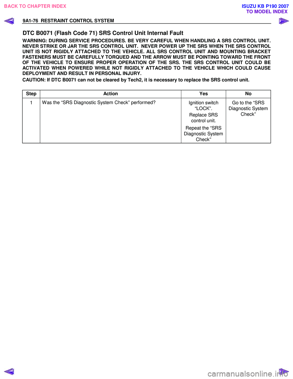
DTC B0071 (Flash Code 71) SRS Control Unit Internal Fault
WARNING: DURING SERVICE PROCEDURES. BE VERY CAREFUL WHEN HANDLING A SRS CONTROL UNIT.
NEVER STRIKE OR JAR THE SRS CONTROL UNIT. NEVER POWER UP THE SRS WHEN THE SRS CONTROL
UNIT IS NOT RIGIDLY ATTACHED TO THE VEHICLE. ALL SRS CONTROL UNIT AND MOUNTING BRACKET
FASTENERS MUST BE CAREFULLY TORQUED AND THE ARROW MUST BE POINTING TOWARD THE FRONT
OF THE VEHICLE TO ENSURE PROPER OPERATION OF THE SRS. THE SRS CONTROL UNIT COULD BE
ACTIVATED WHEN POWERED WHILE NOT RIGIDLY ATTACHED TO THE VEHICLE WHICH COULD CAUSE
DEPLOYMENT AND RESULT IN PERSONAL INJURY.
CAUTION: If DTC B0071 can not be cleared by Tech2, it is necessary to replace the SRS control unit.
Step Action Yes No
1 W as the “SRS Diagnostic System Check” performed?
Ignition switch
“LOCK”.
Replace SRS control unit.
Repeat the “SRS
Diagnostic System Check” Go to the “SRS
Diagnostic System Check”
BACK TO CHAPTER INDEX TO MODEL INDEXISUZU KB P190 2007
Page 5859 of 6020
11A-8 IMMOBILIZER CONTROL SYSTEM (4JK1/4JJ1/HFV6)
Diagnostic Information and Procedures
Diagnostic Starting Point - Immobilizer
Controls
Begin the system diagnosis with Diagnostic System
Check - Immobilizer Controls. The Diagnostic System
Check - Immobilizer Controls will provide the following
information:
• The identification of the control modules which command the system.
• The ability of the control modules to communicate through the serial data circuit.
• The identification of any stored diagnostic trouble codes (DTCs) and the their statuses.
The use of the Diagnostic System Check - Immobilizer
Controls will identify the correct procedure for
diagnosing the system and where the procedure is
located.
Diagnostic System Check - Immobilizer
Controls
Description
The Diagnostic System Check - Immobilizer Controls is
an organized approach to identifying a condition that is
created by a malfunction in the electronic immobilizer
control system. The Diagnostic System Check must be
the starting point for any immobilizer system concern.
The Diagnostic System Check directs the service
technician to the next logical step in order to diagnose
the concern. Understanding and correctly using the
diagnostic table reduces diagnostic time, and prevents
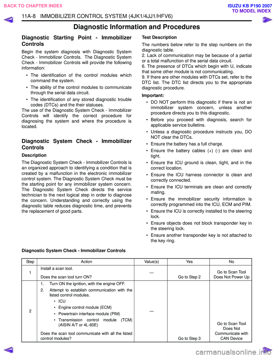
the replacement of good parts. Test Description
The numbers below refer to the step numbers on the
diagnostic table.
2. Lack of communication may be because of a partial
or a total malfunction of the serial data circuit.
6. The presence of DTCs which begin with U, indicate
that some other module is not communicating.
9. If there are other modules with DTCs set, refer to the
DTC list. The DTC list directs you to the appropriate
diagnostic procedure.
Important: • DO NOT perform this diagnostic if there is not an immobilizer system concern, unless another
procedure directs you to this diagnostic.
• Before you proceed with diagnosis, search for applicable service bulletins.
• Unless a diagnostic procedure instructs you, DO NOT clear the DTCs.
• Ensure the battery has a full charge.
• Ensure the battery cables (+) (-) are clean and tight.
• Ensure the ICU ground is clean, tight, and in the correct location.
• Ensure the ICU harness connector is clean and correctly connected.
• Ensure the ICU terminals are clean and correctly mating.
• Ensure the immobilizer security information is correctly programmed into the ICU, ECM and PIM.
• Ensure the ICU is correctly installed to the steering lock.
• Ensure objects does not block transponder key in the steering lock.
• Ensure another transponder key is not attached to the key ring.
Diagnostic System Check - Immobilizer Controls
Step Action Value(s)Yes No
1 Install a scan tool.
Does the scan tool turn ON? —
Go to Step 2 Go to Scan Tool
Does Not Power Up
2 1. Turn ON the ignition, with the engine OFF.
2. Attempt to establish communication with the listed control modules.
•ICU
• Engine control module (ECM)
• Powertrain interface module (PIM)
• Transmission control module (TCM) (AISIN A/T or 4L-60E)
Does the scan tool communicate with all the listed
control modules? —
Go to Step 3 Go to Scan Tool
Does Not
Communicate with CAN Device
BACK TO CHAPTER INDEX TO MODEL INDEX
ISUZU KB P190 2007