2007 ISUZU KB P190 service
[x] Cancel search: servicePage 4608 of 6020
7B1-2 MANUAL TRANSMISSION
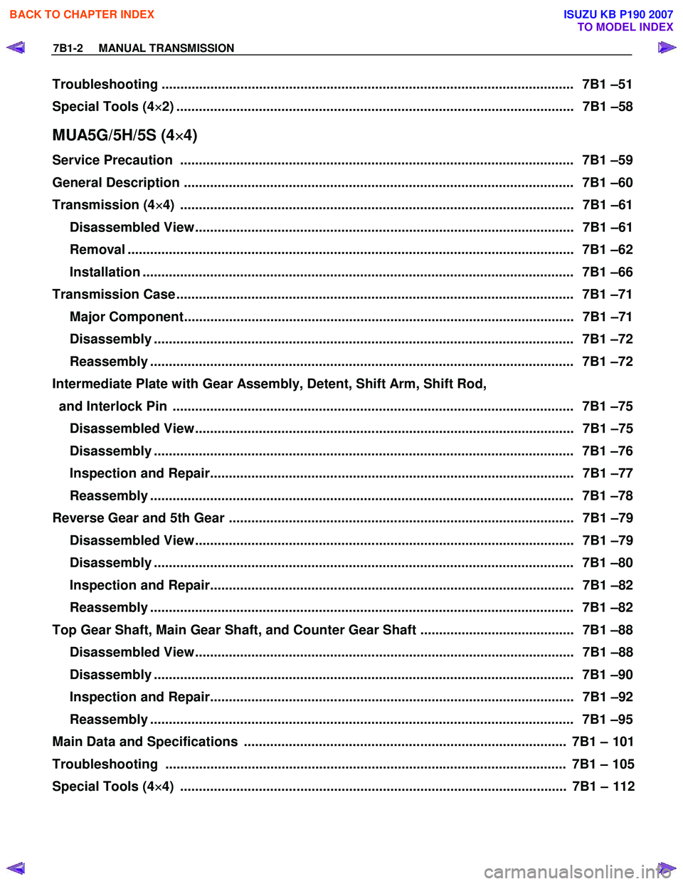
Troubleshooting .............................................................................................................. 7 B1 –51
Special Tools (4 ×
××
×
2) .......................................................................................................... 7B1 –58
MUA5G/5H/5S (4×
××
×
4)
Service Precaution ......................................................................................................... 7B 1 –59
General Description ........................................................................................................ 7B 1 –60
Transmission (4 ×
××
×
4) ......................................................................................................... 7B1 –61
Disassembled View..................................................................................................... 7B1 –61
Removal ....................................................................................................................... 7B1 –62
Installation ................................................................................................................... 7B1 –66
Transmission Case .......................................................................................................... 7B1 –71
Major Component........................................................................................................ 7B1 –71
Disassembly ................................................................................................................ 7B1 –72
Reassembly ................................................................................................................. 7B1 –72
Intermediate Plate with Gear Assembly, Detent, Shift Arm, Shift Rod,
and Interlock Pin ........................................................................................................... 7B1 –75
Disassembled View..................................................................................................... 7B1 –75
Disassembly ................................................................................................................ 7B1 –76
Inspection and Repair................................................................................................. 7B1 –77
Reassembly ................................................................................................................. 7B1 –78
Reverse Gear and 5th Gear ............................................................................................ 7B1 –79 Disassembled View..................................................................................................... 7B1 –79
Disassembly ................................................................................................................ 7B1 –80
Inspection and Repair................................................................................................. 7B1 –82
Reassembly ................................................................................................................. 7B1 –82
Top Gear Shaft, Main Gear Shaft, and Counter Gear Shaft ......................................... 7B1 –88 Disassembled View..................................................................................................... 7B1 –88
Disassembly ................................................................................................................ 7B1 –90
Inspection and Repair................................................................................................. 7B1 –92
Reassembly ................................................................................................................. 7B1 –95
Main Data and Specifications ...................................................................................... 7B1 – 101
Troubleshooting ........................................................................................................... 7B1 – 105
Special Tools (4 ×
××
×
4) ....................................................................................................... 7B1 – 112
BACK TO CHAPTER INDEX
TO MODEL INDEX
ISUZU KB P190 2007
Page 4609 of 6020
MANUAL TRANSMISSION 7B1-3
Service Precaution
WARNING: THIS VEHICLE HAS A SUPPLEMENTAL
RESTRAINT SYSTEM (SRS). REFER TO THE SRS
COMPONENT AND WIRING LOCATION VIEW IN
ORDER TO DETERMINE WHETHER YOU ARE
PERFORMING SERVICE ON OR NEAR THE SRS
COMPONENTS OR THE SRS WIRING. WHEN YOU
ARE PERFORMING SERVICE ON OR NEAR THE
SRS COMPONENTS OR THE SRS WIRING, REFER
TO THE SRS SERVICE INFORMATION. FAILURE TO
FOLLOW WARNINGS COULD RESULT IN POSSIBLE
AIR BAG DEPLOYMENT, PERSONAL INJURY, OR
OTHERWISE UNNECESSARY SRS SYSTEM
REPAIRS.
CAUTION: Always use the correct fastener in the
proper location. When you replace a fastener, use
ONLY the exact part number for that application.
ISUZU/GM will call out those fasteners that require a
replacement after removal. ISUZU/GM will also call
out the fasteners that require thread lockers o
r
thread sealant. UNLESS OTHERWISE SPECIFIED,
do not use supplemental coatings (paints, greases,
or other corrosion inhibitors) on threaded fasteners
or fastener joint interfaces. Generally, such coatings
adversely affect the fastener torque and the joint
clamping force, and may damage the fastener.
When you install fasteners, use the correct
tightening sequence and specifications. Following
these instructions can help you avoid damage to
parts and systems.
BACK TO CHAPTER INDEX
TO MODEL INDEX
ISUZU KB P190 2007
Page 4665 of 6020
MANUAL TRANSMISSION 7B1-59
Service Precaution
WARNING: THIS VEHICLE HAS A SUPPLE MENTAL
RESTRAINT SYSTEM (SRS). REFER TO THE SRS
COMPONENT AND WIRING LOCATION VIEW IN
ORDER TO DETERMINE WHETHER YOU ARE
PERFORMING SERVICE ON OR NEAR THE SRS
COMPONENTS OR THE SRS WIRING. WHEN YOU
ARE PERFORMING SERVICE ON OR NEAR THE
SRS COMPONENTS OR THE SRS WIRING, REFER
TO THE SRS SERVICE INFORMATION. FAILURE TO
FOLLOW WARNINGS COULD RESULT IN POSSIBLE
AIR BAG DEPLOYMENT, PERSONAL INJURY, OR
OTHERWISE UNNECESSARY SRS SYSTEM
REPAIRS.
CAUTION: Always use the correct fastener in the
proper location. When you replace a fastener, use
ONLY the exact part number for that application.
ISUZU/GM will call out those fasteners that require a
replacement after removal. ISUZU/GM will also call
out the fasteners that require thread lockers o
r
thread sealant. UNLESS OTHERWISE SPECIFIED,
do not use supplemental coatings (paints, greases,
or other corrosion inhibitors) on threaded fasteners
or fastener joint interfaces. Generally, such coatings
adversely affect the fastener torque and the joint
clamping force, and may damage the fastener.
When you install fasteners, use the correct
tightening sequence and specifications. Following
these instructions can help you avoid damage to
parts and systems.
BACK TO CHAPTER INDEX
TO MODEL INDEX
ISUZU KB P190 2007
Page 4779 of 6020
CLUTCH 7C-1
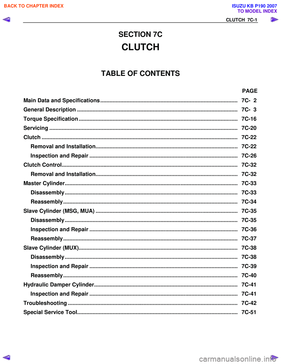
SECTION 7C
CLUTCH
TABLE OF CONTENTS
PAGE
Main Data and Specifications ......................................................................................... 7C- 2
General Description ........................................................................................................ 7C- 3
Torque Specification ....................................................................................................... 7C- 16
Servicing ...................................................................................................................... .... 7C-20
Clutch ......................................................................................................................... ...... 7C-22
Removal and Installation............................................................................................ 7C-22
Inspection and Repair ................................................................................................ 7C-26
Clutch Control................................................................................................................. . 7C-32
Removal and Installation............................................................................................ 7C-32
Master Cylinder................................................................................................................ 7C-33
Disassembly ................................................................................................................ 7C- 33
Reassembly ................................................................................................................. 7C- 34
Slave Cylinder (MSG, MUA) ............................................................................................ 7C-35 Disassembly ................................................................................................................ 7C- 35
Inspection and Repair ................................................................................................ 7C-36
Reassembly ................................................................................................................. 7C- 37
Slave Cylinder (MUX)....................................................................................................... 7C- 38
Disassembly ................................................................................................................ 7C- 38
Inspection and Repair ................................................................................................ 7C-39
Reassembly ................................................................................................................. 7C- 40
Hydraulic Damper Cylinder............................................................................................. 7C-41 Inspection and Repair ................................................................................................ 7C-41
Troubleshooting .............................................................................................................. 7 C-42
Special Service Tool........................................................................................................ 7C -51
BACK TO CHAPTER INDEX
TO MODEL INDEX
ISUZU KB P190 2007
Page 4793 of 6020
CLUTCH 7C-15
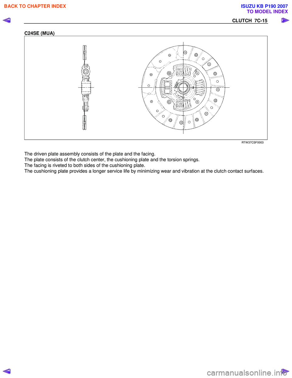
C24SE (MUA)
RTW 37CSF0003
The driven plate assembly consists of the plate and the facing.
The plate consists of the clutch center, the cushioning plate and the torsion springs.
The facing is riveted to both sides of the cushioning plate.
The cushioning plate provides a longer service life by minimizing wear and vibration at the clutch contact surfaces.
BACK TO CHAPTER INDEX
TO MODEL INDEX
ISUZU KB P190 2007
Page 4798 of 6020
7C-20 CLUTCH
SERVICING
Servicing refers to general maintenance procedures to be performed by qualified service personnel.
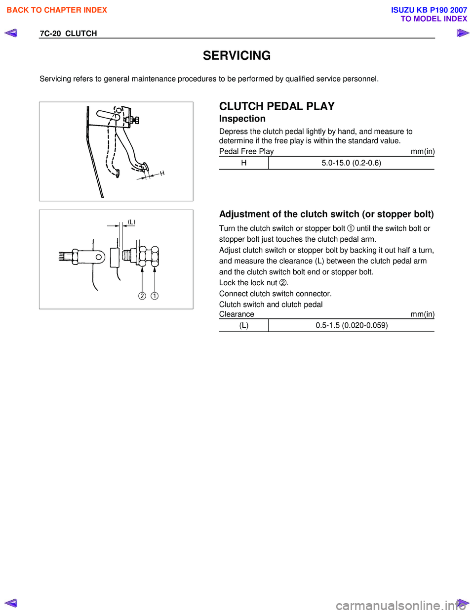
CLUTCH PEDAL PLAY
Inspection
Depress the clutch pedal lightly by hand, and measure to
determine if the free play is within the standard value.
Pedal Free Play mm(in)
H 5.0-15.0 (0.2-0.6)
Adjustment of the clutch switch (or stopper bolt)
Turn the clutch switch or stopper bolt 1 until the switch bolt
or
stopper bolt just touches the clutch pedal arm.
Adjust clutch switch or stopper bolt
by backing it out half a turn,
and measure the clearance (L) between the clutch pedal arm
and the clutch switch bolt end or stopper bolt.
Lock the lock nut
2.
Connect clutch switch connector.
Clutch switch and clutch pedal
Clearance mm(in)
(L) 0.5-1.5 (0.020-0.059)
BACK TO CHAPTER INDEX
TO MODEL INDEX
ISUZU KB P190 2007
Page 4829 of 6020
CLUTCH 7C-51
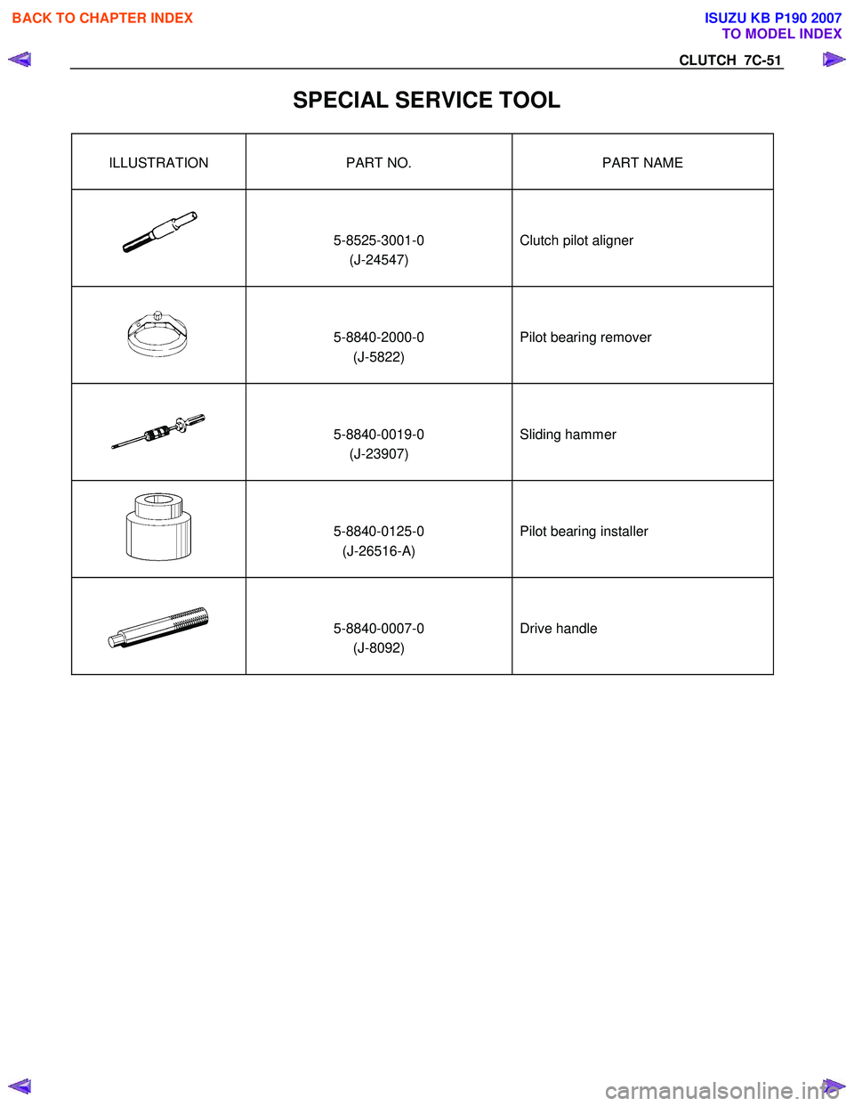
SPECIAL SERVICE TOOL
ILLUSTRATION PART NO. PART NAME
5-8525-3001-0 (J-24547)
Clutch pilot aligner
5-8840-2000-0 (J-5822)
Pilot bearing remover
5-8840-0019-0 (J-23907)
Sliding hammer
5-8840-0125-0 (J-26516-A)
Pilot bearing installer
5-8840-0007-0 (J-8092)
Drive handle
BACK TO CHAPTER INDEX
TO MODEL INDEX
ISUZU KB P190 2007
Page 4831 of 6020
TRANSFER CASE 7D-1
SECTION 7D
TRANSFER CASE
TABLE OF CONTENTS
PAGE
Service Precaution ......................................................................................................... 7D – 2
General Description ........................................................................................................ 7D – 3
On-Vehicle Service ......................................................................................................... 7D – 4
Transfer Case Oil Level ............................................................................................... 7D – 4
Transfer Case Oil Change ........................................................................................... 7D – 5
Transfer Case Front Oil Seal ...................................................................................... 7D – 6
Transfer Case Rear Oil Seal ........................................................................................ 7D – 9
Transfer Case Assembly ................................................................................................ 7D – 11
Transfer Case Assembly and Associated Parts ........................................................ 7D – 11
Removal ....................................................................................................................... . 7D – 12
Installation .................................................................................................................. .. 7D – 12
Transfer Control Unit ...................................................................................................... 7D – 16
Removal ....................................................................................................................... . 7D – 17
Installation .................................................................................................................. .. 7D – 17
Transfer Disassembly .................................................................................................... 7D – 18
Removal ....................................................................................................................... . 7D – 18
Inspection and Repair ................................................................................................. 7D – 27
Inspection and Repair (Transfer Case Assembly) .................................................... 7D – 27
Reassembly .................................................................................................................. 7 D – 31
Main Data and Specifications ........................................................................................ 7D – 41
Special Tools ................................................................................................................ 7D – 44
BACK TO CHAPTER INDEX
TO MODEL INDEX
ISUZU KB P190 2007