Page 1396 of 3061
DTC P0181 FTT SENSOR
EC-313
< SERVICE INFORMATION >
C
D
E
F
G
H
I
J
K
L
MA
EC
N
P O
NG >> Replace “fuel level sensor unit and fuel pump”.
6.CHECK INTERMITTENT INCIDENT
Refer to EC-138
.
>>INSPECTION END
Component InspectionINFOID:0000000003531805
FUEL TANK TEMPERATURE SENSOR
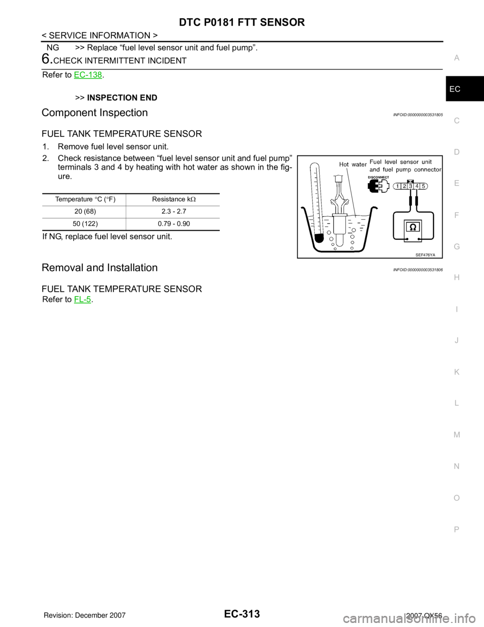
1. Remove fuel level sensor unit.
2. Check resistance between “fuel level sensor unit and fuel pump”
terminals 3 and 4 by heating with hot water as shown in the fig-
ure.
If NG, replace fuel level sensor unit.
Removal and InstallationINFOID:0000000003531806
FUEL TANK TEMPERATURE SENSOR
Refer to FL-5.
Temperature °C (°F) Resistance kΩ
20 (68) 2.3 - 2.7
50 (122) 0.79 - 0.90
SEF476YA
Page 1399 of 3061
EC-316
< SERVICE INFORMATION >
DTC P0182, P0183 FTT SENSOR
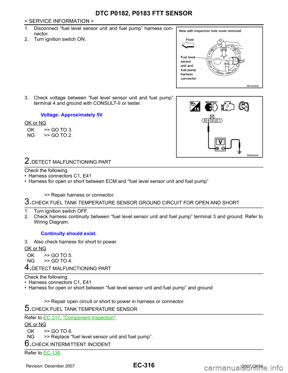
1. Disconnect “fuel level sensor unit and fuel pump” harness con-
nector.
2. Turn ignition switch ON.
3. Check voltage between “fuel level sensor unit and fuel pump”
terminal 4 and ground with CONSULT-II or tester.
OK or NG
OK >> GO TO 3.
NG >> GO TO 2.
2.DETECT MALFUNCTIONING PART
Check the following.
• Harness connectors C1, E41
• Harness for open or short between ECM and “fuel level sensor unit and fuel pump”
>> Repair harness or connector.
3.CHECK FUEL TANK TEMPERATURE SENSOR GROUND CIRCUIT FOR OPEN AND SHORT
1. Turn ignition switch OFF.
2. Check harness continuity between “fuel level sensor unit and fuel pump” terminal 3 and ground. Refer to
Wiring Diagram.
3. Also check harness for short to power.
OK or NG
OK >> GO TO 5.
NG >> GO TO 4.
4.DETECT MALFUNCTIONING PART
Check the following.
• Harness connectors C1, E41
• Harness for open or short between “fuel level sensor unit and fuel pump” and ground
>> Repair open circuit or short to power in harness or connector.
5.CHECK FUEL TANK TEMPERATURE SENSOR
Refer to EC-317, "
Component Inspection".
OK or NG
OK >> GO TO 6.
NG >> Replace “fuel level sensor unit and fuel pump”.
6.CHECK INTERMITTENT INCIDENT
Refer to EC-138
.
BBIA0583E
Voltage: Approximately 5V
PBIB0932E
Continuity should exist.
Page 1400 of 3061
DTC P0182, P0183 FTT SENSOR
EC-317
< SERVICE INFORMATION >
C
D
E
F
G
H
I
J
K
L
MA
EC
N
P O
>>INSPECTION END
Component InspectionINFOID:0000000003531812
FUEL TANK TEMPERATURE SENSOR
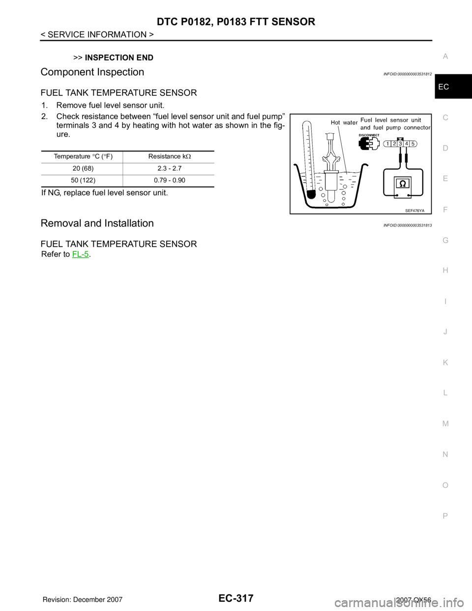
1. Remove fuel level sensor unit.
2. Check resistance between “fuel level sensor unit and fuel pump”
terminals 3 and 4 by heating with hot water as shown in the fig-
ure.
If NG, replace fuel level sensor unit.
Removal and InstallationINFOID:0000000003531813
FUEL TANK TEMPERATURE SENSOR
Refer to FL-5.
Temperature °C (°F) Resistance kΩ
20 (68) 2.3 - 2.7
50 (122) 0.79 - 0.90
SEF476YA
Page 1410 of 3061
DTC P0300 - P0308 MULTIPLE CYLINDER MISFIRE, NO. 1 - 8 CYLINDER MIS-
FIRE
EC-327
< SERVICE INFORMATION >
C
D
E
F
G
H
I
J
K
L
MA
EC
N
P O
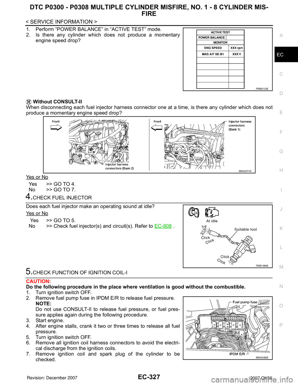
1. Perform “POWER BALANCE” in “ACTIVE TEST” mode.
2. Is there any cylinder which does not produce a momentary
engine speed drop?
Without CONSULT-II
When disconnecting each fuel injector harness connector one at a time, is there any cylinder which does not
produce a momentary engine speed drop?
Ye s o r N o
Yes >> GO TO 4.
No >> GO TO 7.
4.CHECK FUEL INJECTOR
Does each fuel injector make an operating sound at idle?
Ye s o r N o
Yes >> GO TO 5.
No >> Check fuel injector(s) and circuit(s). Refer to EC-608
.
5.CHECK FUNCTION OF IGNITION COIL-I
CAUTION:
Do the following procedure in the place where ventilation is good without the combustible.
1. Turn ignition switch OFF.
2. Remove fuel pump fuse in IPDM E/R to release fuel pressure.
NOTE:
Do not use CONSULT-II to release fuel pressure, or fuel pres-
sure applies again during the following procedure.
3. Start engine.
4. After engine stalls, crank it two or three times to release all fuel
pressure.
5. Turn ignition switch OFF.
6. Remove all ignition coil harness connectors to avoid the electri-
cal discharge from the ignition coils.
7. Remove ignition coil and spark plug of the cylinder to be
checked.
PBIB0133E
BBIA0374E
PBIB1986E
BBIA0380E
Page 1412 of 3061
DTC P0300 - P0308 MULTIPLE CYLINDER MISFIRE, NO. 1 - 8 CYLINDER MIS-
FIRE
EC-329
< SERVICE INFORMATION >
C
D
E
F
G
H
I
J
K
L
MA
EC
N
P O
Check compression pressure. Refer to EM-64, "On-Vehicle Service".
OK or NG
OK >> GO TO 10.
NG >> Check pistons, piston rings, valves, valve seats and cylinder head gaskets.
10.CHECK FUEL PRESSURE
1. Install all removed parts.
2. Release fuel pressure to zero. Refer to EC-80, "
Fuel Pressure Check" .
3. Install fuel pressure gauge and check fuel pressure. Refer to EC-80, "
Fuel Pressure Check" .
OK or NG
OK >> GO TO 12.
NG >> GO TO 11.
11 .DETECT MALFUNCTIONING PART
Check the following.
• Fuel pump and circuit (Refer to EC-613
.)
• Fuel pressure regulator (Refer to EC-80, "
Fuel Pressure Check" .)
• Fuel lines
• Fuel filter for clogging
>> Repair or replace.
12.CHECK IGNITION TIMING
Check the following items. Refer to EC-71, "
Basic Inspection" .
OK or NG
OK >> GO TO 13.
NG >> Follow the EC-71, "
Basic Inspection" .
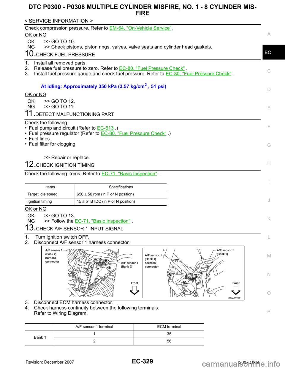
13.CHECK A/F SENSOR 1 INPUT SIGNAL
1. Turn ignition switch OFF.
2. Disconnect A/F sensor 1 harness connector.
3. Disconnect ECM harness connector.
4. Check harness continuity between the following terminals.
Refer to Wiring Diagram.At idling: Approximately 350 kPa (3.57 kg/cm
2 , 51 psi)
Items Specifications
Target idle speed 650 ± 50 rpm (in P or N position)
Ignition timing 15 ± 5° BTDC (in P or N position)
A/F sensor 1 terminal ECM terminal
Bank 1135
256
BBIA0376E
Page 1435 of 3061
EC-352
< SERVICE INFORMATION >
DTC P0420, P0430 THREE WAY CATALYST FUNCTION
CAUTION:
Do the following procedure in the place where ventilation is good without the combustible.
1. Turn ignition switch OFF.
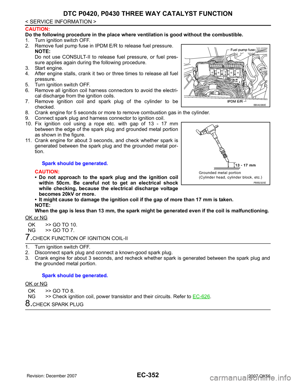
2. Remove fuel pump fuse in IPDM E/R to release fuel pressure.
NOTE:
Do not use CONSULT-II to release fuel pressure, or fuel pres-
sure applies again during the following procedure.
3. Start engine.
4. After engine stalls, crank it two or three times to release all fuel
pressure.
5. Turn ignition switch OFF.
6. Remove all ignition coil harness connectors to avoid the electri-
cal discharge from the ignition coils.
7. Remove ignition coil and spark plug of the cylinder to be
checked.
8. Crank engine for 5 seconds or more to remove combustion gas in the cylinder.
9. Connect spark plug and harness connector to ignition coil.
10. Fix ignition coil using a rope etc. with gap of 13 - 17 mm
between the edge of the spark plug and grounded metal portion
as shown in the figure.
11. Crank engine for about 3 seconds, and check whether spark is
generated between the spark plug and the grounded metal por-
tion.
CAUTION:
• Do not approach to the spark plug and the ignition coil
within 50cm. Be careful not to get an electrical shock
while checking, because the electrical discharge voltage
becomes 20kV or more.
• It might cause to damage the ignition coil if the gap of more than 17 mm is taken.
NOTE:
When the gap is less than 13 mm, the spark might be generated even if the coil is malfunctioning.
OK or NG
OK >> GO TO 10.
NG >> GO TO 7.
7.CHECK FUNCTION OF IGNITION COIL-II
1. Turn ignition switch OFF.
2. Disconnect spark plug and connect a known-good spark plug.
3. Crank engine for about 3 seconds, and recheck whether spark is generated between the spark plug and
the grounded metal portion.
OK or NG
OK >> GO TO 8.
NG >> Check ignition coil, power transistor and their circuits. Refer to EC-626
.
8.CHECK SPARK PLUGSpark should be generated.
BBIA0380E
PBIB2325E
Spark should be generated.
Page 1444 of 3061
DTC P0442 EVAP CONTROL SYSTEM
EC-361
< SERVICE INFORMATION >
C
D
E
F
G
H
I
J
K
L
MA
EC
N
P O
2. Check for genuine NISSAN fuel filler cap design.
OK or NG
OK >> GO TO 2.
NG >> Replace with genuine NISSAN fuel filler cap.
2.CHECK FUEL FILLER CAP INSTALLATION
Check that the cap is tightened properly by rotating the cap clockwise.
OK or NG
OK >> GO TO 3.
NG >> 1. Open fuel filler cap, then clean cap and fuel filler neck threads using air blower.
2. Retighten until ratcheting sound is heard.
3.CHECK FUEL FILLER CAP FUNCTION
Check for air releasing sound while opening the fuel filler cap.
OK or NG
OK >> GO TO 5.
NG >> GO TO 4.
4.CHECK FUEL TANK VACUUM RELIEF VALVE
Refer to EC-35, "
Component Inspection" .
OK or NG
OK >> GO TO 5.
NG >> Replace fuel filler cap with a genuine one.
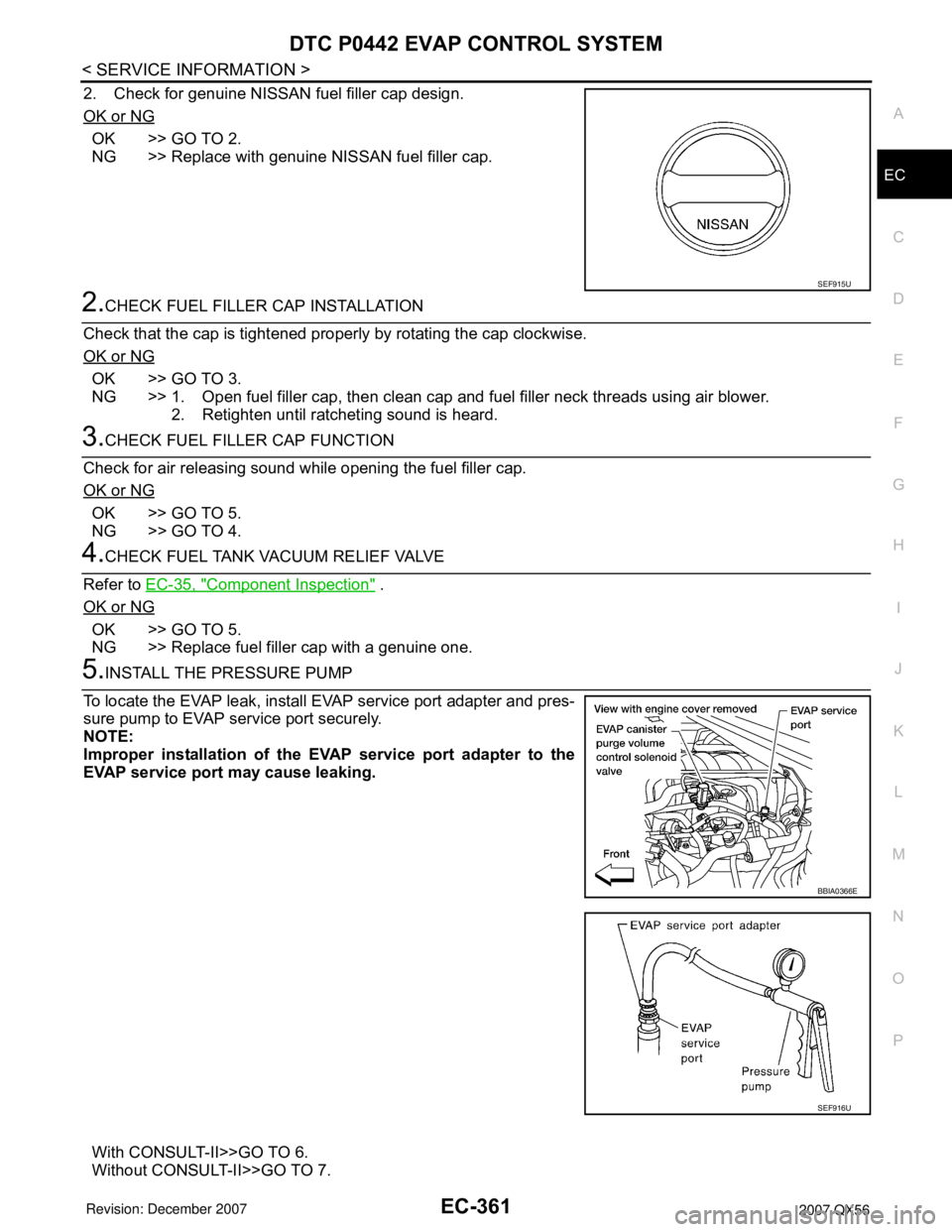
5.INSTALL THE PRESSURE PUMP
To locate the EVAP leak, install EVAP service port adapter and pres-
sure pump to EVAP service port securely.
NOTE:
Improper installation of the EVAP service port adapter to the
EVAP service port may cause leaking.
With CONSULT-II>>GO TO 6.
Without CONSULT-II>>GO TO 7.
SEF915U
BBIA0366E
SEF916U
Page 1500 of 3061
DTC P0456 EVAP CONTROL SYSTEM
EC-417
< SERVICE INFORMATION >
C
D
E
F
G
H
I
J
K
L
MA
EC
N
P O
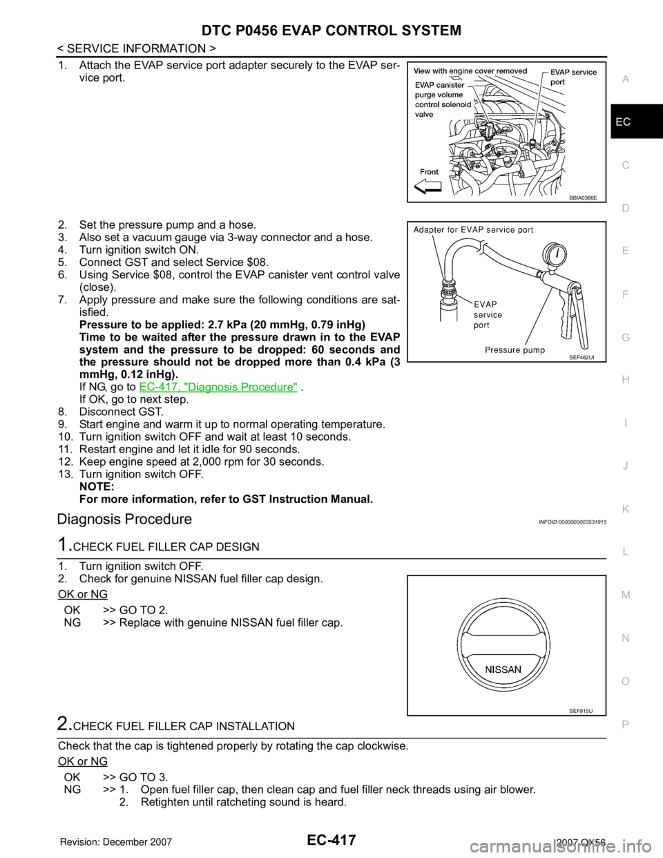
1. Attach the EVAP service port adapter securely to the EVAP ser-
vice port.
2. Set the pressure pump and a hose.
3. Also set a vacuum gauge via 3-way connector and a hose.
4. Turn ignition switch ON.
5. Connect GST and select Service $08.
6. Using Service $08, control the EVAP canister vent control valve
(close).
7. Apply pressure and make sure the following conditions are sat-
isfied.
Pressure to be applied: 2.7 kPa (20 mmHg, 0.79 inHg)
Time to be waited after the pressure drawn in to the EVAP
system and the pressure to be dropped: 60 seconds and
the pressure should not be dropped more than 0.4 kPa (3
mmHg, 0.12 inHg).
If NG, go to EC-417, "
Diagnosis Procedure" .
If OK, go to next step.
8. Disconnect GST.
9. Start engine and warm it up to normal operating temperature.
10. Turn ignition switch OFF and wait at least 10 seconds.
11. Restart engine and let it idle for 90 seconds.
12. Keep engine speed at 2,000 rpm for 30 seconds.
13. Turn ignition switch OFF.
NOTE:
For more information, refer to GST Instruction Manual.
Diagnosis ProcedureINFOID:0000000003531915
1.CHECK FUEL FILLER CAP DESIGN
1. Turn ignition switch OFF.
2. Check for genuine NISSAN fuel filler cap design.
OK or NG
OK >> GO TO 2.
NG >> Replace with genuine NISSAN fuel filler cap.
2.CHECK FUEL FILLER CAP INSTALLATION
Check that the cap is tightened properly by rotating the cap clockwise.
OK or NG
OK >> GO TO 3.
NG >> 1. Open fuel filler cap, then clean cap and fuel filler neck threads using air blower.
2. Retighten until ratcheting sound is heard.
BBIA0366E
SEF462UI
SEF915U