Page 2832 of 3061
TF-10
< SERVICE INFORMATION >
NOISE, VIBRATION AND HARSHNESS (NVH) TROUBLESHOOTING
NOISE, VIBRATION AND HARSHNESS (NVH) TROUBLESHOOTING
NVH Troubleshooting ChartINFOID:0000000003532512
Use the chart below to help you find the cause of the symptom. The numbers indicate the order of the inspec-
tion. If necessary, repair or replace these parts.
Reference page
TF-11TF-128TF-128TF-128TF-128
SUSPECTED PARTS
(Possible cause)
TRANSFER FLUID (Level low)
TRANSFER FLUID (Wrong)
TRANSFER FLUID (Level too high)
LIQUID GASKET (Damaged)
O-RING (Worn or damaged)
OIL SEAL (Worn or damaged)
SHIFT FORK (Worn or damaged)
GEAR (Worn or damaged)
BEARING (Worn or damaged)
SymptomNoise 1 2 3 3
Transfer fluid leakage 31222
Hard to shift or will not shift 1 1 2
Page 2833 of 3061

TRANSFER FLUID
TF-11
< SERVICE INFORMATION >
C
E
F
G
H
I
J
K
L
MA
B
TF
N
O
P
TRANSFER FLUID
ReplacementINFOID:0000000003532513
DRAINING
1. Stop the engine.
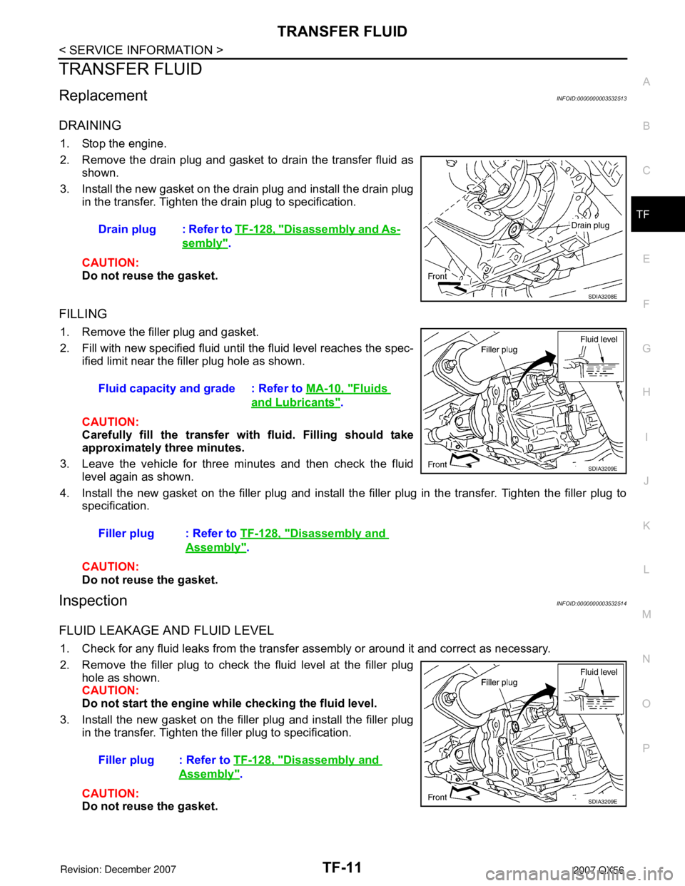
2. Remove the drain plug and gasket to drain the transfer fluid as
shown.
3. Install the new gasket on the drain plug and install the drain plug
in the transfer. Tighten the drain plug to specification.
CAUTION:
Do not reuse the gasket.
FILLING
1. Remove the filler plug and gasket.
2. Fill with new specified fluid until the fluid level reaches the spec-
ified limit near the filler plug hole as shown.
CAUTION:
Carefully fill the transfer with fluid. Filling should take
approximately three minutes.
3. Leave the vehicle for three minutes and then check the fluid
level again as shown.
4. Install the new gasket on the filler plug and install the filler plug in the transfer. Tighten the filler plug to
specification.
CAUTION:
Do not reuse the gasket.
InspectionINFOID:0000000003532514
FLUID LEAKAGE AND FLUID LEVEL
1. Check for any fluid leaks from the transfer assembly or around it and correct as necessary.
2. Remove the filler plug to check the fluid level at the filler plug
hole as shown.
CAUTION:
Do not start the engine while checking the fluid level.
3. Install the new gasket on the filler plug and install the filler plug
in the transfer. Tighten the filler plug to specification.
CAUTION:
Do not reuse the gasket.Drain plug : Refer to TF-128, "
Disassembly and As-
sembly".
SDIA3208E
Fluid capacity and grade : Refer to MA-10, "Fluids
and Lubricants".
Filler plug : Refer to TF-128, "
Disassembly and
Assembly".
SDIA3209E
Filler plug : Refer to TF-128, "Disassembly and
Assembly".
SDIA3209E
Page 2834 of 3061
TF-12
< SERVICE INFORMATION >
ALL-MODE 4WD SYSTEM
ALL-MODE 4WD SYSTEM
Cross-Sectional ViewINFOID:0000000003532515
Power TransferINFOID:0000000003532516
POWER TRANSFER DIAGRAM
1. Center case 2. Front case 3. Internal gear
4. Planetary carrier assembly 5. Sun gear assembly 6. Main shaft
7. L-H sleeve 8. L-H fork 9. Shift rod
10. 2-4 sleeve 11. 2-4 fork 12. Drive chain
13. Front drive shaft 14. Control valve assembly 15. Transfer motor
16. Rear case 17. Clutch piston 18. Press flange
19. Multiple disc clutch 20. Clutch hub assembly 21. Clutch drum assembly
WDIA0202E
Page 2835 of 3061
ALL-MODE 4WD SYSTEM
TF-13
< SERVICE INFORMATION >
C
E
F
G
H
I
J
K
L
MA
B
TF
N
O
P
POWER TRANSFER FLOW
1. Center case 2. Chain 3. Multiple disc clutch
4. Rear case 5. Mainshaft 6. Clutch hub assembly
7. Sub oil pump 8. Transfer motor 9. Control valve
10. Front drive shaft 11. Drain plug 12. 2-4 sleeve
13. Sun gear assembly 14. L-H sleeve 15. Planetary carrier assembly
16. Internal gear 17. Front case
LDIA0053E
Page 2836 of 3061
TF-14
< SERVICE INFORMATION >
ALL-MODE 4WD SYSTEM
System Description
INFOID:0000000003532517
CONTROL SYSTEM
SDIA3327E
Page 2837 of 3061
ALL-MODE 4WD SYSTEM
TF-15
< SERVICE INFORMATION >
C
E
F
G
H
I
J
K
L
MA
B
TF
N
O
P
ALL-MODE 4WD Transfer Basic Control
WDIA0162E
Page 2838 of 3061

TF-16
< SERVICE INFORMATION >
ALL-MODE 4WD SYSTEM
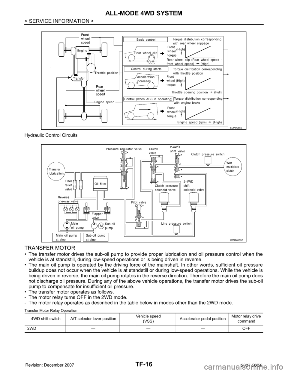
Hydraulic Control Circuits
TRANSFER MOTOR
• The transfer motor drives the sub-oil pump to provide proper lubrication and oil pressure control when the
vehicle is at standstill, during low-speed operations or is being driven in reverse.
• The main oil pump is operated by the driving force of the mainshaft. In other words, sufficient oil pressure
buildup does not occur when the vehicle is at standstill or during low-speed operations. While the vehicle is
being driven in reverse, the main oil pump rotates in the reverse direction. Therefore the main oil pump does
not discharge oil pressure. During any of the above vehicle operations, the transfer motor drives the sub-oil
pump to compensate for insufficient oil pressure.
• The transfer motor operates as follows.
- The motor relay turns OFF in the 2WD mode.
- The motor relay operates as described in the table below in modes other than the 2WD mode.
Transfer Motor Relay Operation
LDIA0055E
WDIA0163E
4WD shift switch A/T selector lever positionVehicle speed
(VSS)Accelerator pedal positionMotor relay drive
command
2WD — — — OFF
Page 2839 of 3061

ALL-MODE 4WD SYSTEM
TF-17
< SERVICE INFORMATION >
C
E
F
G
H
I
J
K
L
MA
B
TF
N
O
P
*: After 2.5 seconds have elapsed.
• 4WD shift switch, PNP switch, Neutral-4LO switch, vehicle speed sensor and throttle position sensor are
used in conjunction with the transfer motor.
WAIT DETECTION SWITCH
• The wait detection switch operates when there is “circulating” torque produced in the propeller shaft (L→H)
or when there is a phase difference between 2-4 sleeve and clutch drum (H→L). After the release of the “cir-
culating” torque, the wait detection switch helps provide the 4WD lock gear (clutch drum) shifts. A difference
may occur between the operation of the 4WD shift switch and actual drive mode. At this point, the wait
detection switch senses an actual drive mode.
• The wait detection switch operates as follows.
- 4WD lock gear (clutch drum) locked: ON
- 4WD lock gear (clutch drum) released: OFF
• The wait detection switch senses an actual drive mode and the 4WD shift indicator lamp indicates the vehi-
cle drive mode.
NEUTRAL-4LO SWITCH
The neutral-4LO switch detects that transfer gear is in neutral or 4LO (or shifting from neutral to 4LO) condi-
tion by L-H shift fork position.
AT P S W I T C H
ATP switch detects if transfer gear is in a neutral condition by L-H shift fork position.
NOTE:
Transfer gear may be in a neutral condition in 4H-4LO.
2-4WD SHIFT SOLENOID VALVE
The 2-4WD shift solenoid valve operates to apply oil pressure to the wet-multiplate clutch, depending on the
drive mode. The driving force is transmitted to the front wheels through the clutch so the vehicle is set in the
4WD mode. Setting the vehicle in the 2WD mode requires no pressure buildup. In other words, pressure force
applied to the wet-multiplate clutch becomes zero.
CLUTCH PRESSURE SOLENOID VALVE
The clutch pressure solenoid valve distributes torque (front and rear) in AUTO mode.
4H (LOCK) and 4LO“N” position 0 — ON
“P” position 00 - 0.07/8 OFF*
0.07/8 - 1/8 HOLD
1/8 - MAX ON
Other than “R” position0 < VSS ≤ 50 km/h (31 MPH)
— ON
50 km/h (31 MPH) < VSS < 55
km/h (34 MPH) HOLD
55 km/h (34 MPH) ≤ VSS OFF
“R” position — — ON
“R” position — — ON
AUTO“P” or “N” position00 - 0.07/8 OFF*
0.07/8 - 1/8 HOLD
1/8 - MAX ON
0 < VSS ≤ 50 km/h (31 MPH)
— ON
50 km/h (31 MPH) < VSS < 55
km/h (34 MPH) HOLD
55 km/h (34 MPH) ≤ VSS OFF
Other than “R”, "P" and "N"
position0 < VSS ≤ 50 km/h (31 MPH)
— ON
50 km/h (31 MPH) < VSS < 55
km/h (34 MPH) HOLD
55 km/h (34 MPH) ≤ VSS OFF 4WD shift switch A/T selector lever positionVehicle speed
(VSS)Accelerator pedal positionMotor relay drive
command