Page 3081 of 4647
FFD-26
FRONT FINAL DRIVE ASSEMBLY
Revision: 2007 April2007 M35/M45
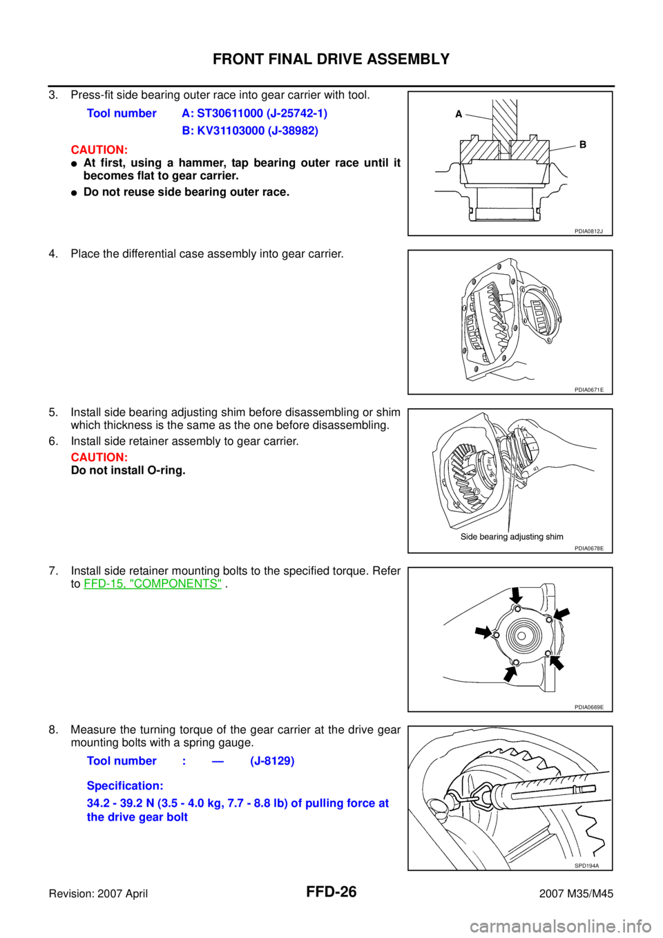
3. Press-fit side bearing outer race into gear carrier with tool.
CAUTION:
�At first, using a hammer, tap bearing outer race until it
becomes flat to gear carrier.
�Do not reuse side bearing outer race.
4. Place the differential case assembly into gear carrier.
5. Install side bearing adjusting shim before disassembling or shim
which thickness is the same as the one before disassembling.
6. Install side retainer assembly to gear carrier.
CAUTION:
Do not install O-ring.
7. Install side retainer mounting bolts to the specified torque. Refer
to FFD-15, "
COMPONENTS" .
8. Measure the turning torque of the gear carrier at the drive gear
mounting bolts with a spring gauge.Tool number A: ST30611000 (J-25742-1)
B: KV31103000 (J-38982)
PDIA0812J
PDIA0671E
PDIA0678E
PDIA0669E
Tool number : — (J-8129)
Specification:
34.2 - 39.2 N (3.5 - 4.0 kg, 7.7 - 8.8 lb) of pulling force at
the drive gear bolt
SPD194A
Page 3087 of 4647

FFD-32
FRONT FINAL DRIVE ASSEMBLY
Revision: 2007 April2007 M35/M45
9. Install drive gear on the mounting bolts, and then tighten to the
specified torque. Refer to FFD-15, "
COMPONENTS" .
CAUTION:
Tighten bolts in a crisscross fashion.
10. Press side bearing inner races to differential case, using the drift
and the base.
CAUTION:
Do not reuse side bearing inner race.
11. Press-fit side bearing outer race into side retainer with the drift
and the drift bar.
CAUTION:
�At first, using a hammer, tap bearing outer race until it
becomes flat to side retainer.
�Do not reuse side bearing outer race.
12. Press-fit side bearing outer race into gear carrier with the drift
and the drift bar.
CAUTION:
�At first, using a hammer, tap bearing outer race until it
becomes flat to gear carrier.
�Do not reuse side bearing outer race.
13. Place the differential case assembly into gear carrier.
14. Measure side bearing preload. If necessary, select the appropri-
ate side bearing adjusting shim. Refer to FFD-25, "
Side Bearing
Preload" .
SDIA0247J
Tool number A: ST33230000 (J-25805-01)
B: ST33061000 (J-8107-2)
PDIA0810J
Tool number A: ST30611000 (J-25742-1)
B: KV31103000 (J-38982)
PDIA0811J
Tool number A: ST30611000 (J-25742-1)
B: KV31103000 (J-38982)
PDIA0812J
PDIA0671E
Page 3088 of 4647
.
16. Apply multi-purpose grease to O-ring (2), and in")
FRONT FINAL DRIVE ASSEMBLY
FFD-33
C
E
F
G
H
I
J
K
L
MA
B
FFD
Revision: 2007 April2007 M35/M45
15. Install selected side bearing adjusting shim (1).
16. Apply multi-purpose grease to O-ring (2), and install it to side
retainer.
CAUTION:
Do not reuse O-ring.
17. Install side retainer assembly to gear carrier.
18. Install side retainer mounting bolts to the specified torque. Refer
to FFD-15, "
COMPONENTS" .
19. Using the drift, press-fit side oil seal so that its surface comes
face to face with the end surface of the side retainer.
CAUTION:
�Do not reuse oil seal.
�When installing, do not incline oil seal.
�Apply multi-purpose grease onto oil seal lips, and gear
oil onto the circumference of oil seal.
20. Using the drift, press-fit side oil seal so that its surface comes
face to face with the end surface of gear carrier.
CAUTION:
�Do not reuse oil seal.
�When installing, do not incline oil seal.
�Apply multi-purpose grease onto oil seal lips, and gear
oil onto the circumference of oil seal.
21. Apply multi-purpose grease to O-ring, and install it to gear car-
rier.
CAUTION:
Do not reuse O-ring.
22. Check and adjust drive gear runout, tooth contact, drive gear to drive pinion backlash, and total preload
torque. Refer to FFD-17, "
Drive Gear Runout" , FFD-17, "Tooth Contact" , FFD-19, "Backlash" , FFD-16,
"Total Preload Torque" .
Recheck above items. Readjust the above description, if necessary.
PDIA0813E
PDIA0669E
Tool number A: ST33400001 (J-26082)
PDIA0787J
Tool number A: KV38102100 (J-25803-01)
PDIA0788J
Page 3089 of 4647

FFD-34
FRONT FINAL DRIVE ASSEMBLY
Revision: 2007 April2007 M35/M45
23. Apply sealant to mating surface of carrier cover.
�Use Genuine Silicone RTV or equivalent. Refer to GI-47,
"Recommended Chemical Products and Sealants" .
CAUTION:
Remove old sealant adhering to mounting surfaces. Also
remove any moisture, oil, or foreign material adhering to
application and mounting surfaces.
24. Install carrier cover on gear carrier and tighten mounting bolts
with the specified torque. Refer to FFD-15, "
COMPONENTS" .
Side Shaft Assembly
1. Using the drift, install side shaft oil seal.
CAUTION:
�Do not reuse oil seal.
�When installing, do not incline oil seal.
�Apply multi-purpose grease onto oil seal lips, and gear
oil onto the circumference of oil seal.
2. Install dust sealed.
3. Support side shaft bearing with the drift, then press side shaft
(1) into the side shaft bearing using a press.
4. Apply multi-purpose grease to O-ring, and install it to extension
tube retainer.
CAUTION:
Do not reuse O-ring.
PDIA0742E
SDIA1648E
Tool number A: KV38100200 ( — )
PDIA0814J
Tool number A: ST30032000 (J-26010-01)
PDIA0815J
Page 3092 of 4647

FL-1
FUEL SYSTEM
B ENGINE
CONTENTS
C
D
E
F
G
H
I
J
K
L
M
SECTION FL
A
FL
Revision: 2007 April2007 M35/M45
FUEL SYSTEM
PREPARATION ........................................................... 2
Commercial Service Tools ........................................ 2
FUEL SYSTEM ........................................................... 3
Checking Fuel Lines ................................................. 3
General Precautions ................................................ 3
FUEL LEVEL SENSOR UNIT, FUEL FILTER AND
FUEL PUMP ASSEMBLY ........................................... 4
Components ............................................................. 4
Removal and Installation .......................................... 4
REMOVAL ............................................................. 4
INSTALLATION ..................................................... 6
INSPECTION AFTER INSTALLATION ................. 7Components ............................................................. 8
Disassembly and Assembly ...................................... 8
DISASSEMBLY ..................................................... 8
ASSEMBLY ........................................................... 9
FUEL TANK .............................................................. 10
Components ........................................................... 10
Removal and Installation ........................................ 10
REMOVAL ........................................................... 10
INSTALLATION ................................................... 11
INSPECTION AFTER INSTALLATION ................ 11
SERVICE DATA AND SPECIFICATIONS (SDS) ...... 13
Standard and Limit .................................................. 13
FUEL TANK ......................................................... 13
Page 3095 of 4647

FL-4
FUEL LEVEL SENSOR UNIT, FUEL FILTER AND FUEL PUMP ASSEMBLY
Revision: 2007 April2007 M35/M45
FUEL LEVEL SENSOR UNIT, FUEL FILTER AND FUEL PUMP ASSEMBLYPFP:17042
ComponentsNBS005RA
Removal and InstallationNBS005RB
REMOVAL
WARNING:
Read “General Precautions” when working on the fuel system. Refer to FL-3, "
General Precautions" .
1. Check fuel level on fuel gauge. If fuel gauge indicates more than
the level as shown in the figure (full or almost full), drain fuel
from fuel tank until fuel gauge indicates level as shown in the fig-
ure or below.
NOTE:
Because fuel will be spilled when removing main and sub fuel
level sensor units for the top of the fuel is above the main and
sub fuel level sensor units installation surface.
�As a guide, fuel level becomes the position as shown in the
figure or below when approximately 20 (5-1/4 US gal, 4-3/8
Imp gal) of fuel are drained from fuel tank.
�In a case that fuel pump does not operate, perform the follow-
ing procedure.
a. Insert hose of less than 25 mm (0.98 in) in diameter into fuel filler tube through fuel filler opening to draw
fuel from fuel filler tube.
b. Disconnect fuel filler hose from fuel filler tube. Refer to FL-10, "
FUEL TANK" .
c. Insert fuel tube into fuel tank through fuel filler hose to draw fuel from fuel tank.
2. Release the fuel pressure from the fuel lines. Refer to EC-88, "
FUEL PRESSURE RELEASE" (VQ35DE)
or EC-790, "
FUEL PRESSURE RELEASE" (VK45DE).
1. Retainer 2.Main fuel level sensor unit, fuel filter
and fuel pump assembly3. O-ring
4. Sub fuel level sensor unit
PBIC1585E
PBIC4760E
Page 3097 of 4647

FL-6
FUEL LEVEL SENSOR UNIT, FUEL FILTER AND FUEL PUMP ASSEMBLY
Revision: 2007 April2007 M35/M45
CAUTION:
�Quick connector can be disconnected when the tabs
are completely depressed. Do not twist it more than
necessary.
�Do not use any tools to disconnected quick connector.
�Keep resin tube away from heat. Be especially careful
when welding near the resin tube.
�Prevent acid liquid such as battery electrolyte, etc.
from getting on resin tube.
�Do not bend or twist resin tube during installation and
disconnection.
�Do not remove the remaining retainer on hard tube (or
the equivalent) except when resin tube or retainer is
replaced.
�When resin tube or hard tube (or the equivalent) is
replaced, also replace retainer with new one.
�To keep the connecting portion clean and to avoid
damage and foreign materials, cover them completely
with plastic bags or something similar.
8. Remove main fuel level sensor unit, fuel filter and fuel pump assembly, and sub fuel level sensor unit as
follows:
CAUTION:
�Do not bend float arm during removal.
�Avoid impacts such as falling when handling components.
a. Removal of main fuel level sensor unit, fuel filter and fuel pump assembly:
i. Remove retainer.
ii. Raise main fuel level sensor unit, fuel filter and fuel pump
assembly, and using snap ring pliers, remove fuel hose connec-
tor.
CAUTION:
Be careful not to damage fuel hose connector by expanding
them excessively.
b. Removal of sub fuel level sensor unit:
i. Remove retainer.
ii. Raise and release sub fuel level sensor unit to remove.
INSTALLATION
Note to the following, and install in the reverse order of removal.Retainer color: Green
SBIA0504E
PBIC0163E
PBIC1578E
Page 3099 of 4647
, then check connections for leaks by applying fu")
FL-8
FUEL LEVEL SENSOR UNIT, FUEL FILTER AND FUEL PUMP ASSEMBLY
Revision: 2007 April2007 M35/M45
1. Turn ignition switch “ON” (with engine stopped), then check connections for leaks by applying fuel pres-
sure to fuel piping.
2. Start engine and let it idle and make sure there are no fuel leaks at the fuel system connections.
ComponentsNBS005RC
Disassembly and AssemblyNBS005RD
CAUTION:
Sub fuel level sensor unit cannot be disassembled and should be replaced as a unit.
DISASSEMBLY
Remove fuel level sensor unit as follows.
1. Disconnect harness connector.
�Hold connector by fingers and pull it out, because there is no
stopper release tab.
2. Using suitable tool, pull up tabs points as shown in the figure
(two points) to release the lock.
CAUTION:
Be careful not to damage it.
3. After fixing tabs are disengaged, slide fuel level sensor unit out
in direction shown by the arrow.
CAUTION:
Do not disassemble fuel filter and fuel pump assembly.
1. Fuel level sensor unit 2. Fuel filter and fuel pump assembly
PBIC1081E
PBIC1078E
PBIC1654E
PBIC1080E