Page 1634 of 4647
TROUBLE DIAGNOSIS
EC-105
[VQ35DE]
C
D
E
F
G
H
I
J
K
L
MA
EC
Revision: 2007 April2007 M35/M45
: Vehicle front
1. Knock sensor 2. Fuel damper 3. Camshaft position sensor (PHASE)
(Bank 1)
4. Fuel injector harness connector 5. Condenser 6. Fuel damper
7. Camshaft position sensor (PHASE)
(Bank 2)8. Fuel pump fuse 9. IPDM E/R
PBIB2788E
Page 1635 of 4647
EC-106
[VQ35DE]
TROUBLE DIAGNOSIS
Revision: 2007 April2007 M35/M45
: Vehicle front
1. Power steering pressure sensor 2. Intake valve timing control solenoid
valve3. Ignition coil harness connector
(Bank 1)
4. Ignition coil harness connector
(Bank 2)5. Intake valve timing control solenoid
valve6. EVAP service port
7. EVAP canister purge volume con-
trol solenoid valve
PBIB2789E
Page 1636 of 4647
TROUBLE DIAGNOSIS
EC-107
[VQ35DE]
C
D
E
F
G
H
I
J
K
L
MA
EC
Revision: 2007 April2007 M35/M45
: Vehicle front
1. Crankshaft position sensor (POS) 2. ICC brake hold relay
(ICC models only)3. EVAP canister vent control valve
4. EVAP control system pressure sen-
sor5. EVAP canister 6. Cooling fan relay
7. Battery current sensor
PBIB2790E
Page 1638 of 4647
TROUBLE DIAGNOSIS
EC-109
[VQ35DE]
C
D
E
F
G
H
I
J
K
L
MA
EC
Revision: 2007 April2007 M35/M45
1. ECM 2. Data link connector 3. Accelerator pedal position sensor
4. Stop lamp switch 5. ICC brake switch
(models with ICC)
ASCD brake switch
(models with ASCD)6. ICC steering switch
(models with ICC)
ASCD steering switch
(models with ASCD)
7. RESUME/ACCELERATE switch 8. SET/COAST switch 9. CANCEL switch
10. DISTANCE switch
(ICC models only)11. MAIN switch
PBIB2680E
Page 1639 of 4647
EC-110
[VQ35DE]
TROUBLE DIAGNOSIS
Revision: 2007 April2007 M35/M45
: Vehicle front
1. Fuel level sensor unit and fuel pump
harness connector2. Fuel level sensor unit and fuel pump 3. Fuel pressure regulator
4. Fuel tank temperature sensor 5. FPCM 6. Dropping resistor
PBIB2681E
Page 1643 of 4647
![INFINITI M35 2007 Factory Service Manual EC-114
[VQ35DE]
TROUBLE DIAGNOSIS
Revision: 2007 April2007 M35/M45
ECM Harness Connector Terminal LayoutNBS004T5
ECM Terminals and Reference ValueNBS004T6
PREPARATION
1. ECM (1) is located behind the](/manual-img/42/57024/w960_57024-1642.png "INFINITI M35 2007 Factory Service Manual EC-114
[VQ35DE]
TROUBLE DIAGNOSIS
Revision: 2007 April2007 M35/M45
ECM Harness Connector Terminal LayoutNBS004T5
ECM Terminals and Reference ValueNBS004T6
PREPARATION
1. ECM (1) is located behind the")
EC-114
[VQ35DE]
TROUBLE DIAGNOSIS
Revision: 2007 April2007 M35/M45
ECM Harness Connector Terminal LayoutNBS004T5
ECM Terminals and Reference ValueNBS004T6
PREPARATION
1. ECM (1) is located behind the passenger side instrument lower
panel. For this inspection, remove passenger side instrument
lower panel.
2. Remove ECM harness connector.
3. When disconnecting ECM harness connector, loosen (A) it with
levers (2) as far as they will go as shown in the figure.
�ECM (1)
�Fasten (B)
4. Connect a break-out box (SST) and Y-cable adapter (SST)
between the ECM and ECM harness connector.
�Use extreme care not to touch 2 pins at one time.
�Data is for comparison and may not be exact.
ECM INSPECTION TABLE
Specification data are reference values and are measured between each terminal and ground.
Pulse signal is measured by CONSULT-II.
CAUTION:
Do not use ECM ground terminals when measuring input/output voltage. Doing so may result in dam-
age to the ECMs transistor. Use a ground other than ECM terminals, such as the ground.
MBIB0045E
PBIB2703E
PBIB2714E
TER-
MINAL
NO.WIRE
COLORITEM CONDITION DATA (DC Voltage)
1 B ECM ground[Engine is running]
�Idle speedBody ground
2SBA/F sensor 1 heater
(bank 1)[Engine is running]
�Warm-up condition
�Idle speedApproximately 5V
PBIB1584E
Page 1644 of 4647
![INFINITI M35 2007 Factory Service Manual TROUBLE DIAGNOSIS
EC-115
[VQ35DE]
C
D
E
F
G
H
I
J
K
L
MA
EC
Revision: 2007 April2007 M35/M453RThrottle control motor relay
power supply[Ignition switch: ON]BATTERY VOLTAGE
(11 - 14V)
4WThrottle contr](/manual-img/42/57024/w960_57024-1643.png "INFINITI M35 2007 Factory Service Manual TROUBLE DIAGNOSIS
EC-115
[VQ35DE]
C
D
E
F
G
H
I
J
K
L
MA
EC
Revision: 2007 April2007 M35/M453RThrottle control motor relay
power supply[Ignition switch: ON]BATTERY VOLTAGE
(11 - 14V)
4WThrottle contr")
TROUBLE DIAGNOSIS
EC-115
[VQ35DE]
C
D
E
F
G
H
I
J
K
L
MA
EC
Revision: 2007 April2007 M35/M453RThrottle control motor relay
power supply[Ignition switch: ON]BATTERY VOLTAGE
(11 - 14V)
4WThrottle control motor
(Close)[Ignition switch: ON]
�Engine stopped
�Selector lever: D
�Accelerator pedal: Fully released0 - 14V
5BThrottle control motor
(Open)[Ignition switch: ON]
�Engine stopped
�Selector lever: D
�Accelerator pedal: Fully depressed0 - 14V
6R/LHeated oxygen sensor 2
heater (bank 2)[Engine is running]
�Engine speed: Below 3,600 rpm after the
following conditions are met
–Engine: After warming up
–Keeping the engine speed between 3,500
and 4,000 rpm for 1 minute and at idle for 1
minute under no load0 - 1.0V
[Ignition switch: ON]
�Engine stopped
[Engine is running]
�Engine speed: Above 3,600 rpmBATTERY VOLTAGE
(11 - 14V)
10 W/GIntake valve timing control
solenoid valve (bank 2)[Engine is running]
�Warm-up condition
�Idle speedBATTERY VOLTAGE
(11 - 14V)
[Engine is running]
�Warm-up condition
�When revving engine up to 2,000rpm
quickly7 - 12V
11 W / RIntake valve timing control
solenoid valve (bank 1)[Engine is running]
�Warm-up condition
�Idle speedBATTERY VOLTAGE
(11 - 14V)
[Engine is running]
�Warm-up condition
�When revving engine up to 2,000rpm
quickly7 - 12V TER-
MINAL
NO.WIRE
COLORITEM CONDITION DATA (DC Voltage)
PBIB1104E
PBIB1105E
PBIB1790E
PBIB1790E
Page 1645 of 4647
EC-116
[VQ35DE]
TROUBLE DIAGNOSIS
Revision: 2007 April2007 M35/M45
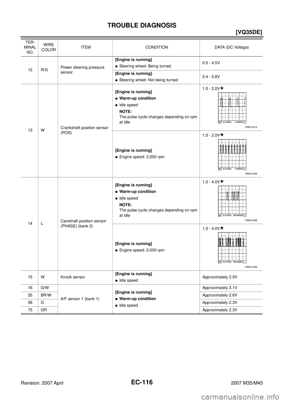
12 R/GPower steering pressure
sensor[Engine is running]�Steering wheel: Being turned0.5 - 4.5V
[Engine is running]
�Steering wheel: Not being turned0.4 - 0.8V
13 WCrankshaft position sensor
(POS)[Engine is running]
�Warm-up condition
�Idle speed
NOTE:
The pulse cycle changes depending on rpm
at idle1.0 - 2.0V
[Engine is running]
�Engine speed: 2,000 rpm1.0 - 2.0V
14 LCamshaft position sensor
(PHASE) (bank 2)[Engine is running]
�Warm-up condition
�Idle speed
NOTE:
The pulse cycle changes depending on rpm
at idle1.0 - 4.0V
[Engine is running]
�Engine speed: 2,000 rpm1.0 - 4.0V
15 W Knock sensor[Engine is running]
�Idle speedApproximately 2.5V
16 G/W
A/F sensor 1 (bank 1)[Engine is running]
�Warm-up condition
�Idle speedApproximately 3.1V
35 BR/WApproximately 2.6V
56 GApproximately 2.3V
75 GRApproximately 2.3V TER-
MINAL
NO.WIRE
COLORITEM CONDITION DATA (DC Voltage)
PBIB1041E
PBIB1042E
PBIB1039E
PBIB1040E
![INFINITI M35 2007 Factory Service Manual TROUBLE DIAGNOSIS
EC-105
[VQ35DE]
C
D
E
F
G
H
I
J
K
L
MA
EC
Revision: 2007 April2007 M35/M45
: Vehicle front
1. Knock sensor 2. Fuel damper 3. Camshaft position sensor (PHASE)
(Bank 1)
4. Fuel inject](/manual-img/42/57024/w960_57024-1633.png "INFINITI M35 2007 Factory Service Manual TROUBLE DIAGNOSIS
EC-105
[VQ35DE]
C
D
E
F
G
H
I
J
K
L
MA
EC
Revision: 2007 April2007 M35/M45
: Vehicle front
1. Knock sensor 2. Fuel damper 3. Camshaft position sensor (PHASE)
(Bank 1)
4. Fuel inject")
![INFINITI M35 2007 Factory Service Manual EC-106
[VQ35DE]
TROUBLE DIAGNOSIS
Revision: 2007 April2007 M35/M45
: Vehicle front
1. Power steering pressure sensor 2. Intake valve timing control solenoid
valve3. Ignition coil harness connector
(](/manual-img/42/57024/w960_57024-1634.png "INFINITI M35 2007 Factory Service Manual EC-106
[VQ35DE]
TROUBLE DIAGNOSIS
Revision: 2007 April2007 M35/M45
: Vehicle front
1. Power steering pressure sensor 2. Intake valve timing control solenoid
valve3. Ignition coil harness connector
(")
![INFINITI M35 2007 Factory Service Manual TROUBLE DIAGNOSIS
EC-107
[VQ35DE]
C
D
E
F
G
H
I
J
K
L
MA
EC
Revision: 2007 April2007 M35/M45
: Vehicle front
1. Crankshaft position sensor (POS) 2. ICC brake hold relay
(ICC models only)3. EVAP canist](/manual-img/42/57024/w960_57024-1635.png "INFINITI M35 2007 Factory Service Manual TROUBLE DIAGNOSIS
EC-107
[VQ35DE]
C
D
E
F
G
H
I
J
K
L
MA
EC
Revision: 2007 April2007 M35/M45
: Vehicle front
1. Crankshaft position sensor (POS) 2. ICC brake hold relay
(ICC models only)3. EVAP canist")
![INFINITI M35 2007 Factory Service Manual TROUBLE DIAGNOSIS
EC-109
[VQ35DE]
C
D
E
F
G
H
I
J
K
L
MA
EC
Revision: 2007 April2007 M35/M45
1. ECM 2. Data link connector 3. Accelerator pedal position sensor
4. Stop lamp switch 5. ICC brake switch](/manual-img/42/57024/w960_57024-1637.png "INFINITI M35 2007 Factory Service Manual TROUBLE DIAGNOSIS
EC-109
[VQ35DE]
C
D
E
F
G
H
I
J
K
L
MA
EC
Revision: 2007 April2007 M35/M45
1. ECM 2. Data link connector 3. Accelerator pedal position sensor
4. Stop lamp switch 5. ICC brake switch")
![INFINITI M35 2007 Factory Service Manual EC-110
[VQ35DE]
TROUBLE DIAGNOSIS
Revision: 2007 April2007 M35/M45
: Vehicle front
1. Fuel level sensor unit and fuel pump
harness connector2. Fuel level sensor unit and fuel pump 3. Fuel pressure re](/manual-img/42/57024/w960_57024-1638.png "INFINITI M35 2007 Factory Service Manual EC-110
[VQ35DE]
TROUBLE DIAGNOSIS
Revision: 2007 April2007 M35/M45
: Vehicle front
1. Fuel level sensor unit and fuel pump
harness connector2. Fuel level sensor unit and fuel pump 3. Fuel pressure re")