Page 3822 of 4647

ENGINE MAINTENANCE (VK45DE ENGINE)
MA-23
C
D
E
F
G
H
I
J
K
MA
B
MA
Revision: 2007 April2007 M35/M45
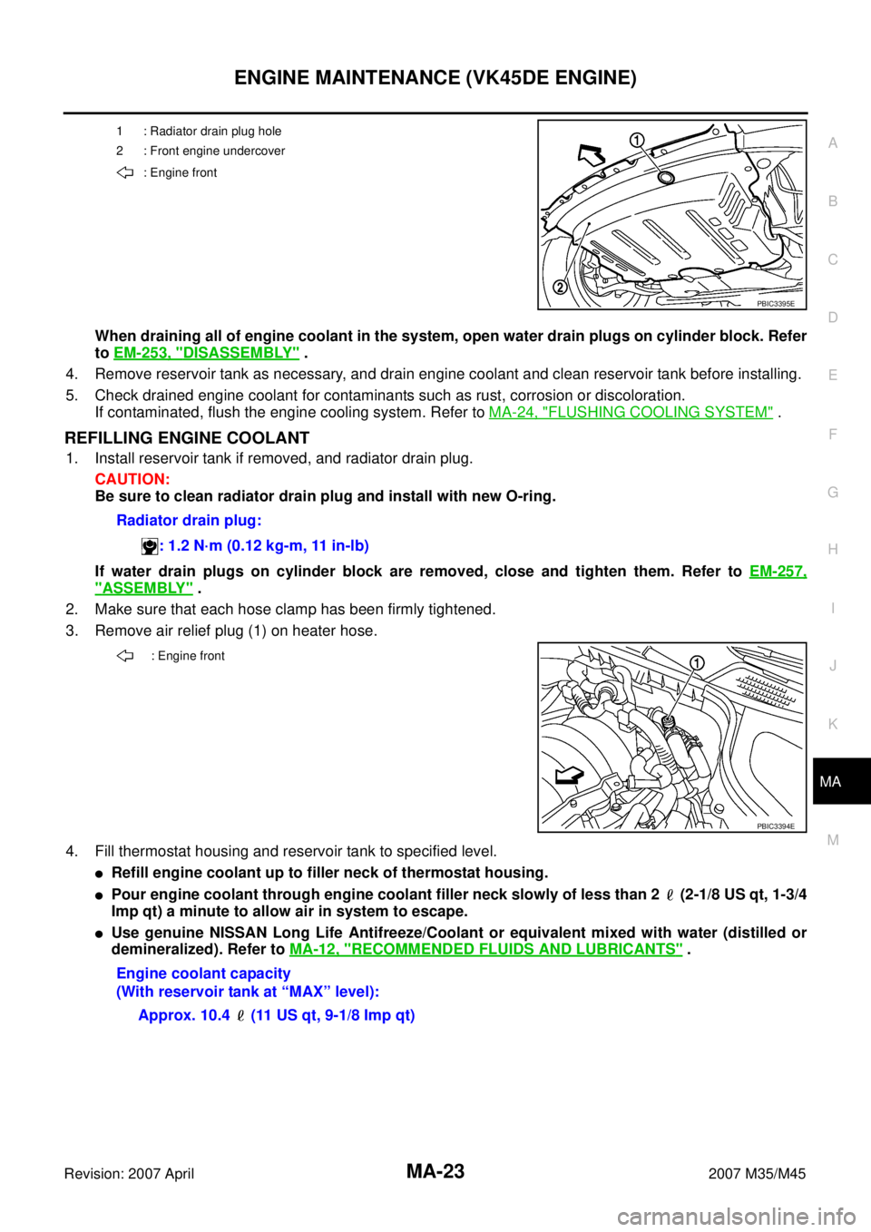
When draining all of engine coolant in the system, open water drain plugs on cylinder block. Refer
to EM-253, "
DISASSEMBLY" .
4. Remove reservoir tank as necessary, and drain engine coolant and clean reservoir tank before installing.
5. Check drained engine coolant for contaminants such as rust, corrosion or discoloration.
If contaminated, flush the engine cooling system. Refer to MA-24, "
FLUSHING COOLING SYSTEM" .
REFILLING ENGINE COOLANT
1. Install reservoir tank if removed, and radiator drain plug.
CAUTION:
Be sure to clean radiator drain plug and install with new O-ring.
If water drain plugs on cylinder block are removed, close and tighten them. Refer to EM-257,
"ASSEMBLY" .
2. Make sure that each hose clamp has been firmly tightened.
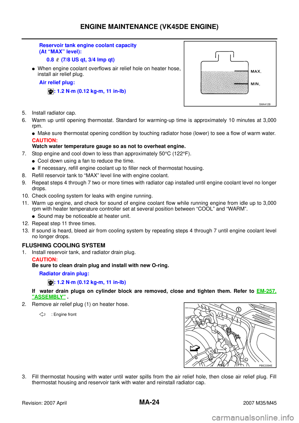
3. Remove air relief plug (1) on heater hose.
4. Fill thermostat housing and reservoir tank to specified level.
�Refill engine coolant up to filler neck of thermostat housing.
�Pour engine coolant through engine coolant filler neck slowly of less than 2 (2-1/8 US qt, 1-3/4
Imp qt) a minute to allow air in system to escape.
�Use genuine NISSAN Long Life Antifreeze/Coolant or equivalent mixed with water (distilled or
demineralized). Refer to MA-12, "
RECOMMENDED FLUIDS AND LUBRICANTS" .
1 : Radiator drain plug hole
2 : Front engine undercover
: Engine front
PBIC3395E
Radiator drain plug:
: 1.2 N·m (0.12 kg-m, 11 in-lb)
: Engine front
PBIC3394E
Engine coolant capacity
(With reservoir tank at “MAX” level):
Approx. 10.4 (11 US qt, 9-1/8 Imp qt)
Page 3823 of 4647

MA-24
ENGINE MAINTENANCE (VK45DE ENGINE)
Revision: 2007 April2007 M35/M45
�When engine coolant overflows air relief hole on heater hose,
install air relief plug.
5. Install radiator cap.
6. Warm up until opening thermostat. Standard for warming-up time is approximately 10 minutes at 3,000
rpm.
�Make sure thermostat opening condition by touching radiator hose (lower) to see a flow of warm water.
CAUTION:
Watch water temperature gauge so as not to overheat engine.
7. Stop engine and cool down to less than approximately 50°C (122°F).
�Cool down using a fan to reduce the time.
�If necessary, refill engine coolant up to filler neck of thermostat housing.
8. Refill reservoir tank to “MAX” level line with engine coolant.
9. Repeat steps 4 through 7 two or more times with radiator cap installed until engine coolant level no longer
drops.
10. Check cooling system for leaks with engine running.
11. Warm up engine, and check for sound of engine coolant flow while running engine from idle up to 3,000
rpm with heater temperature controller set at several position between “COOL” and “WARM”.
�Sound may be noticeable at heater unit.
12. Repeat step 11 three times.
13. If sound is heard, bleed air from cooling system by repeating steps 4 through 7 until engine coolant level
no longer drops.
FLUSHING COOLING SYSTEM
1. Install reservoir tank, and radiator drain plug.
CAUTION:
Be sure to clean drain plug and install with new O-ring.
If water drain plugs on cylinder block are removed, close and tighten them. Refer to EM-257,
"ASSEMBLY" .
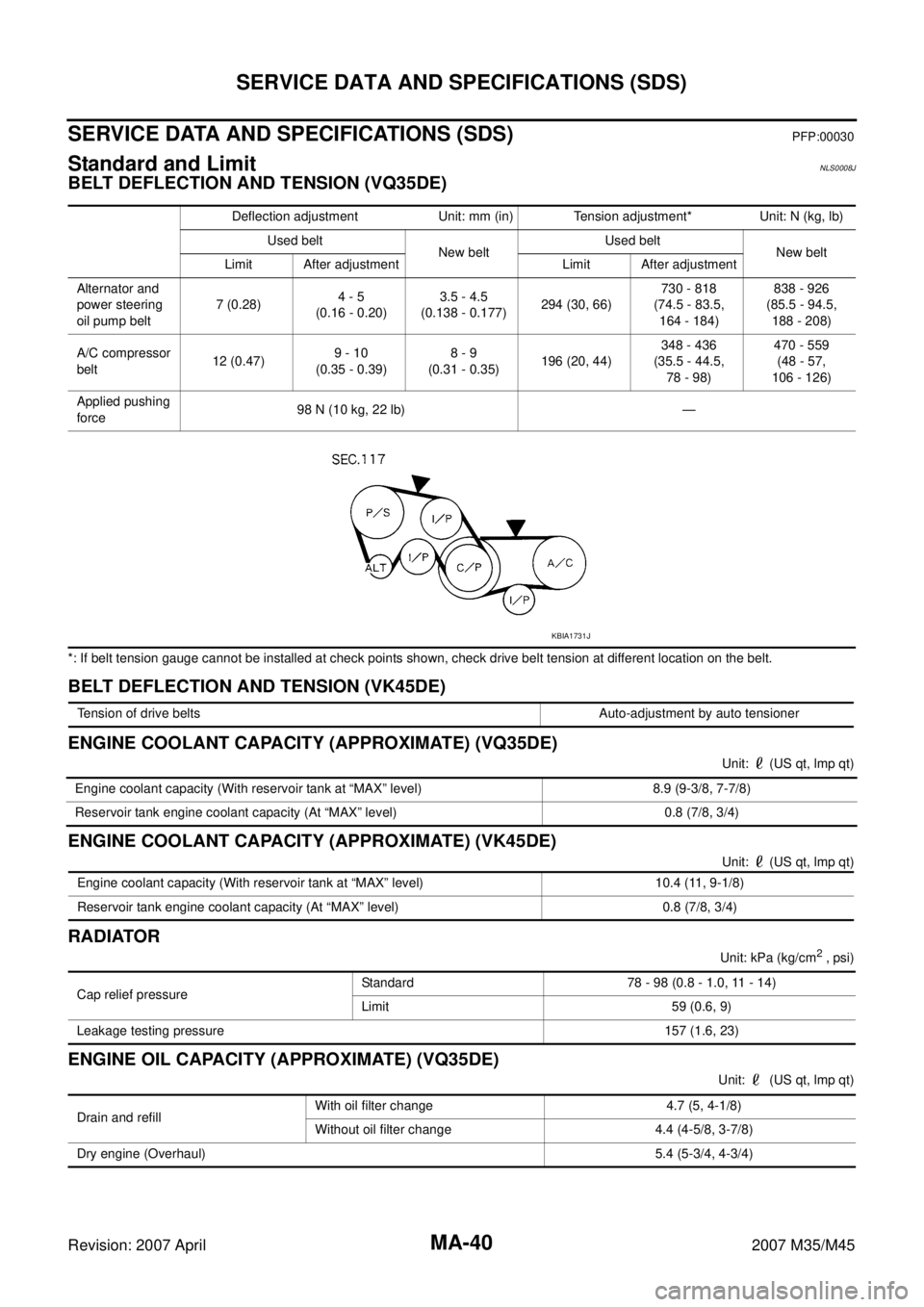
2. Remove air relief plug (1) on heater hose.
3. Fill thermostat housing with water until water spills from the air relief hole, then close air relief plug. Fill
thermostat housing and reservoir tank with water and reinstall radiator cap. Reservoir tank engine coolant capacity
(At “MAX” level):
0.8 (7/8 US qt, 3/4 lmp qt)
Air relief plug:
: 1.2 N·m (0.12 kg-m, 11 in-lb)
SMA412B
Radiator drain plug:
: 1.2 N·m (0.12 kg-m, 11 in-lb)
: Engine front
PBIC3394E
Page 3839 of 4647

MA-40
SERVICE DATA AND SPECIFICATIONS (SDS)
Revision: 2007 April2007 M35/M45
SERVICE DATA AND SPECIFICATIONS (SDS)PFP:00030
Standard and LimitNLS0008J
BELT DEFLECTION AND TENSION (VQ35DE)
*: If belt tension gauge cannot be installed at check points shown, check drive belt tension at different location on the belt.
BELT DEFLECTION AND TENSION (VK45DE)
ENGINE COOLANT CAPACITY (APPROXIMATE) (VQ35DE)
Unit: (US qt, lmp qt)
ENGINE COOLANT CAPACITY (APPROXIMATE) (VK45DE)
Unit: (US qt, lmp qt)
RADIATOR
Unit: kPa (kg/cm2 , psi)
ENGINE OIL CAPACITY (APPROXIMATE) (VQ35DE)
Unit: (US qt, lmp qt) Deflection adjustment Unit: mm (in) Tension adjustment* Unit: N (kg, lb)
Used belt
New beltUsed belt
New belt
Limit After adjustment Limit After adjustment
Alternator and
power steering
oil pump belt7 (0.28)4 - 5
(0.16 - 0.20)3.5 - 4.5
(0.138 - 0.177)294 (30, 66)730 - 818
(74.5 - 83.5,
164 - 184)838 - 926
(85.5 - 94.5,
188 - 208)
A/C compressor
belt12 (0.47)9 - 10
(0.35 - 0.39)8 - 9
(0.31 - 0.35)196 (20, 44)348 - 436
(35.5 - 44.5,
78 - 98)470 - 559
(48 - 57,
106 - 126)
Applied pushing
force98 N (10 kg, 22 lb) —
KBIA1731J
Tension of drive belts Auto-adjustment by auto tensioner
Engine coolant capacity (With reservoir tank at “MAX” level) 8.9 (9-3/8, 7-7/8)
Reservoir tank engine coolant capacity (At “MAX” level) 0.8 (7/8, 3/4)
Engine coolant capacity (With reservoir tank at “MAX” level) 10.4 (11, 9-1/8)
Reservoir tank engine coolant capacity (At “MAX” level) 0.8 (7/8, 3/4)
Cap relief pressureStandard 78 - 98 (0.8 - 1.0, 11 - 14)
Limit 59 (0.6, 9)
Leakage testing pressure157 (1.6, 23)
Drain and refill With oil filter change 4.7 (5, 4-1/8)
Without oil filter change 4.4 (4-5/8, 3-7/8)
Dry engine (Overhaul) 5.4 (5-3/4, 4-3/4)
Page 4194 of 4647

CHARGING SYSTEM
SC-33
C
D
E
F
G
H
I
J
L
MA
B
SC
Revision: 2007 April2007 M35/M45
VK45DE ENGINE MODELS
Removal
1. Disconnect the battery cable from the negative terminal.
2. Remove engine front undercover, using power tools.
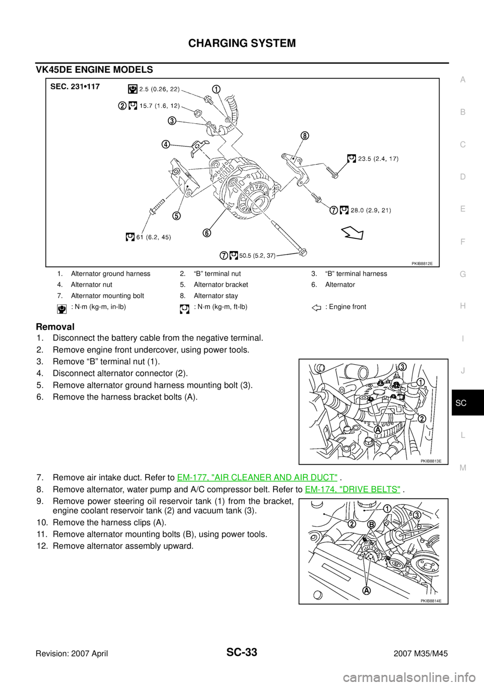
3. Remove “B” terminal nut (1).
4. Disconnect alternator connector (2).
5. Remove alternator ground harness mounting bolt (3).
6. Remove the harness bracket bolts (A).
7. Remove air intake duct. Refer to EM-177, "
AIR CLEANER AND AIR DUCT" .
8. Remove alternator, water pump and A/C compressor belt. Refer to EM-174, "
DRIVE BELTS" .
9. Remove power steering oil reservoir tank (1) from the bracket,
engine coolant reservoir tank (2) and vacuum tank (3).
10. Remove the harness clips (A).
11. Remove alternator mounting bolts (B), using power tools.
12. Remove alternator assembly upward.
1. Alternator ground harness 2. “B” terminal nut 3. “B” terminal harness
4. Alternator nut 5. Alternator bracket 6. Alternator
7. Alternator mounting bolt 8. Alternator stay
: N·m (kg-m, in-lb) : N·m (kg-m, ft-lb) : Engine front
PKIB8812E
PKIB8813E
PKIB8814E