STEERING COLUMN
PS-13
C
D
E
F
H
I
J
K
L
MA
B
PS
Revision: 2007 April2007 M35/M45
STEERING COLUMNPFP:48810
Removal and InstallationNGS000DA
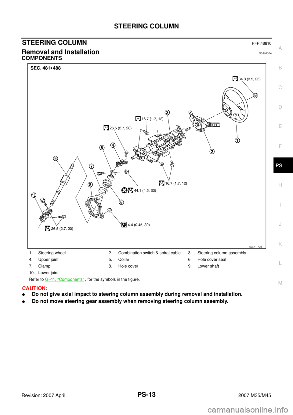
COMPONENTS
CAUTION:
�Do not give axial impact to steering column assembly during removal and installation.
�Do not move steering gear assembly when removing steering column assembly.
1. Steering wheel 2. Combination switch & spiral cable 3. Steering column assembly
4. Upper joint 5. Collar 6. Hole cover seal
7. Clamp 8. Hole cover 9. Lower shaft
10. Lower joint
Refer to GI-11, "
Components" , for the symbols in the figure.
SGIA1172E
PS-14
STEERING COLUMN
Revision: 2007 April2007 M35/M45
REMOVAL OF UPPER JOINT, COLLAR, HOLE COVER SEAL, HOLE COVER, LOWER SHAFT
AND LOWER JOINT
1. Set vehicle to the straight ahead-position.
2. Remove fixing bolts and nut of upper joint (1), then remove
upper joint (1), collar (2) from lower shaft and steering column
assembly.
3. Raise vehicle.
4. Remove lower side fixing bolt of lower joint.
5. Remove upper side fixing bolt of lower joint, then remove lower
joint from lower shaft and steering gear assembly.
6. Remove lower shaft from vehicle.
7. Lowering vehicle.
8. Loosen clamp, and then remove hole cover seal from hole
cover.
9. Remove mounting nuts of hole cover, and then remove clamp
and hole cover from dash panel.
INSPECTION AFTER REMOVAL
Check each part of upper joint, collar, hole cover seal, hole cover, lower shaft and lower joint for damage or
other malfunctions. Replace if there are.
INSTALLATION OF UPPER JOINT, COLLAR, HOLE COVER SEAL, HOLE COVER, LOWER
SHAFT AND LOWER JOINT
�Installation is the reverse order of removal. For tightening torque, refer to PS-13, "COMPONENTS" .
�When installing upper joint, the angle which upper joint yoke (1)
forms with shaft center groove (A) should be at 90°.
�When installing lower joint to steering gear assembly, follow the
procedure listed below.
–Set rack of steering gear in the neutral position.
NOTE:
To get the neutral position of rack, turn gear-sub assembly and
measure the distance of inner socket, and then measure the
intermediate position of the distance.
SGIA1181E
SGIA0844E
SGIA0845E
SGIA1290E
PS-16
STEERING COLUMN
Revision: 2007 April2007 M35/M45
INSPECTION AFTER REMOVAL
�Check each part of steering column assembly for damage or other malfunctions. Replace if there are.
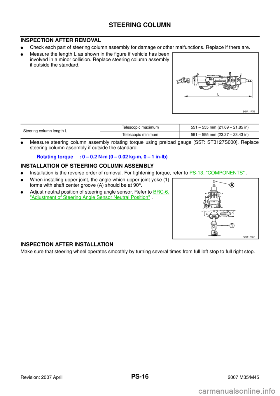
�Measure the length L as shown in the figure if vehicle has been
involved in a minor collision. Replace steering column assembly
if outside the standard.
�Measure steering column assembly rotating torque using preload gauge [SST: ST3127S000]. Replace
steering column assembly if outside the standard.
INSTALLATION OF STEERING COLUMN ASSEMBLY
�Installation is the reverse order of removal. For tightening torque, refer to PS-13, "COMPONENTS" .
�When installing upper joint, the angle which upper joint yoke (1)
forms with shaft center groove (A) should be at 90°.
�Adjust neutral position of steering angle sensor. Refer to BRC-6,
"Adjustment of Steering Angle Sensor Neutral Position" .
INSPECTION AFTER INSTALLATION
Make sure that steering wheel operates smoothly by turning several times from full left stop to full right stop.
SGIA1177E
Steering column length LTelescopic maximum 551 – 555 mm (21.69 – 21.85 in)
Telescopic minimum 591 – 595 mm (23.27 – 23.43 in)
Rotating torque : 0 – 0.2 N·m (0 – 0.02 kg-m, 0 – 1 in-lb)
SGIA1290E