2007 INFINITI M35 oil pressure
[x] Cancel search: oil pressurePage 3325 of 4647

IDX-6
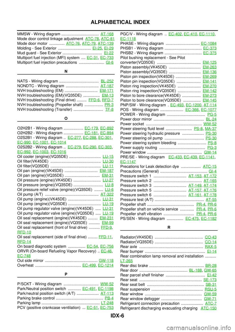
ALPHABETICAL INDEX
MMSW - Wiring diagram .................................. AT-168
Mode door control linkage adjustment ATC-78, ATC-81
Mode door motor .............. ATC-76, ATC-79, ATC-139
Molding - See Exterior .............................. EI-25, EI-29
Mud guard - See Exterior .................................... EI-22
Multiport fuel injection (MFI) system .... EC-31, EC-733
Multiport fuel injection precautions ....................... GI-6
N
NATS - Wiring diagram .................................... BL-252
NONDTC - Wiring diagram .............................. AT-187
NVH troubleshooting (EM) .............................. EM-171
NVH troubleshooting (EM)(VQ35DE) ............... EM-13
NVH troubleshooting (Final drive) ......... FFD-6, RFD-7
NVH troubleshooting (Propeller shaft) ................. PR-3
NVH troubleshooting (Transfer) ........................... TF-8
O
O2H2B1 - Wiring diagram .................. EC-179
, EC-892
O2H2B2 - Wiring diagram .................. EC-181, EC-894
O2S2B1 - Wiring diagram .. EC-277, EC-288, EC-301,
EC-990
, EC-1001, EC-1014
O2S2B2 - Wiring diagram .. EC-279, EC-290, EC-303,
EC-992
, EC-1003, EC-1016
Oil cooler (engine)(VQ35DE) ............................. LU-15
Oil filter(VK45DE) .............................................. LU-30
Oil filter(VQ35DE) .............................................. LU-11
Oil pan (engine)(VK45DE) .............................. EM-187
Oil pan (engine)(VQ35DE) ................................ EM-31
Oil pressure (engine)(VK45DE) ......................... LU-27
Oil pressure (engine)(VQ35DE) ........................... LU-8
Oil pressure relief valve (engine)(VQ35DE) ........ LU-6
Oil pump (A/T) ................................................. AT-322
Oil pump (engine)(VK45DE) .............................. LU-31
Oil pump (engine)(VQ35DE) .............................. LU-19
Oil pump regulator valve (engine)(VK45DE) ..... LU-31
Oil pump regulator valve (engine)(VQ35DE) ..... LU-19
Oil seal replacement (engine)(VK45DE) ......... EM-231
Oil seal replacement (engine)(VQ35DE) .......... EM-99
Oil seal replacement (front of final drive) .......... FFD-9,
RFD-10
Oil seal replacement (side of final drive) ......... FFD-11,
RFD-14
On board diagnostic system ................ EC-54, EC-756
ORVR (On-board Refueling Vapor Recovery) .. EC-46,
EC-748
Out side mirror ................................................ GW-118
Overheat .......................................... EC-499, EC-1214
P
P/SCKT - Wiring diagram ................................ WW-52
Park/Neutral position switch ............ EC-491, EC-1198
Park/neutral position switch (A/T) .................... AT-113
Parking brake control ........................................... PB-4
Parking lamp ..................................................... LT-248
PCV (positive crankcase ventilation) ... EC-51, EC-753
PGC/V - Wiring diagram .. EC-402, EC-410, EC-1110,
EC-1118
PHASE - Wiring diagram ............................... EC-1084
PHSB1 - Wiring diagram .................................. EC-373
PHSB2 - Wiring diagram .................................. EC-375
Pilot bushing replacement - See Pilot
converter(VQ35DE) ........................................ EM-125
Piston assembly(VK45DE) ............................. EM-263
Piston assembly(VQ35DE) ............................. EM-136
Piston pin inspection(VK45DE) ....................... EM-269
Piston pin inspection(VQ35DE) ...................... EM-141
Piston ring inspection(VK45DE) ..................... EM-270
Piston ring inspection(VQ35DE) ..................... EM-142
Piston to bore clearance(VK45DE) ................. EM-273
Piston to bore clearance(VQ35DE) ................ EM-145
PNP/SW - Wiring diagram . EC-493, EC-1200, AT-114
POS - Wiring diagram ..................... EC-366, EC-1077
POWER - Wiring diagram ................................... PG-5
Power door mirror .............................................. BL-24
Power socket ................................................... WW-52
Power steering fluid level ........................ PS-8, MA-37
Power steering hydraulic pressure .................... PS-30
Power steering oil pump .................................... PS-30
Power steering system bleeding .......................... PS-8
Power supply routing .......................................... PG-3
Power window .................................................. GW-14
PRE/SE - Wiring diagram EC-433, EC-439, EC-1141,
EC-1147
Precations for Leak detection dye .................. ATC-15
Precautions (General) ........................................... GI-4
Pressure switch 1 .............................. AT-153, AT-172
Pressure switch 2 ............................................ AT-165
Pressure switch 3 .............................. AT-149, AT-174
Pressure switch 5 .............................. AT-157, AT-176
Pressure switch 6 .............................. AT-161, AT-178
Pressure test (A/T) ............................................. AT-55
Propeller shaft ........................................... PR-4, PR-6
Propeller shaft on vehicle service ............. PR-4, PR-6
Propeller shaft vibration ............................ PR-4, PR-6
PS/SEN - Wiring diagram ............... EC-475, EC-1182
R
Radiator(VK45DE) ............................................ CO-43
Radiator(VQ35DE) ............................................ CO-14
Rear axle .......................................................... RAX-5
Rear bumper ....................................................... EI-14
Rear combination lamp removal and installation ..........
LT-265
Rear disc brake .................................................. BR-28
Rear door ............................................ BL-188, GW-65
Rear parcel shelf finisher .................................... EI-42
Rear seat ......................................................... SE-173
Rear seat belt .................................................... SB-31
Rear suspension ............................................... RSU-5
Rear window .................................................... GW-59
Rear window defogger ..................................... GW-71
Refrigerant connection precaution .................... ATC-7
Refrigerant discharging evacuating charging ATC-150
Page 3400 of 4647
![INFINITI M35 2007 Factory Service Manual TROUBLE DIAGNOSIS
LAN-53
[CAN]
C
D
E
F
G
H
I
J
L
MA
B
LAN
Revision: 2007 April2007 M35/M45
Ignition switch ON signal T R R
Ignition switch signal T R R
Key ID signal T R
Key switch signal T R
Low beam INFINITI M35 2007 Factory Service Manual TROUBLE DIAGNOSIS
LAN-53
[CAN]
C
D
E
F
G
H
I
J
L
MA
B
LAN
Revision: 2007 April2007 M35/M45
Ignition switch ON signal T R R
Ignition switch signal T R R
Key ID signal T R
Key switch signal T R
Low beam](/manual-img/42/57024/w960_57024-3399.png)
TROUBLE DIAGNOSIS
LAN-53
[CAN]
C
D
E
F
G
H
I
J
L
MA
B
LAN
Revision: 2007 April2007 M35/M45
Ignition switch ON signal T R R
Ignition switch signal T R R
Key ID signal T R
Key switch signal T R
Low beam request signal T R
Oil pressure switch signalTR
RT
Position light request signal T R R
Rear window defogger switch signal T R
Sleep wake up signal T R R R R
Theft warning horn request signal T R
Trunk switch signal T R R
Turn indicator signal T R R
A/T CHECK indicator lamp signal T R
A/T position indicator signal R T R R R
A/T self-diagnosis signal R T
Current gear position signal T R R
Manual mode indicator signal T R R
N range signal T R R
Output shaft revolution signal R R T R
P range signal T R R R R
R range signal T R R R
Turbine revolution signal R T R
A/C switch/indicator signalTR
RT
System setting signalTR R
RT T
Door lock/unlock trunk open request signal R T
Hazard and horn request signal R T
Key warning signal T R
Meter display signalTR
RT
Panic alarm request signal R T
Power window open request signal R T
A/C evaporator temperature signal R T
Distance to empty signal R T
Fuel level low warning signal R T
Fuel level sensor signal R T
Manual mode shift down signal R T
Manual mode shift up signal R T
Manual mode signal R T
Not manual mode signal R T
Parking brake switch signal R TSignals
ECM
AFS
*1
BCM
LANE
*2
TCM
AV
I-KEY
M&A
STRG
TPMS
RAS
*3
PSB
ADP
ABS
ICC
*4
IPDM-E
Page 3403 of 4647
![INFINITI M35 2007 Factory Service Manual LAN-56
[CAN]
TROUBLE DIAGNOSIS
Revision: 2007 April2007 M35/M45
Ignition switch ON signal T R R
Ignition switch signal T R R
Key ID signal T R
Key switch signal T R
Low beam request signal T R
Oil pre INFINITI M35 2007 Factory Service Manual LAN-56
[CAN]
TROUBLE DIAGNOSIS
Revision: 2007 April2007 M35/M45
Ignition switch ON signal T R R
Ignition switch signal T R R
Key ID signal T R
Key switch signal T R
Low beam request signal T R
Oil pre](/manual-img/42/57024/w960_57024-3402.png)
LAN-56
[CAN]
TROUBLE DIAGNOSIS
Revision: 2007 April2007 M35/M45
Ignition switch ON signal T R R
Ignition switch signal T R R
Key ID signal T R
Key switch signal T R
Low beam request signal T R
Oil pressure switch signalTR
RT
Position light request signal T R R
Rear window defogger switch signal T R
Sleep wake up signal T R R R R
Theft warning horn request signal T R
Trunk switch signal T R R
Turn indicator signal T R R
A/T CHECK indicator lamp signal T R
A/T position indicator signal R T R R R
A/T self-diagnosis signal R T
Current gear position signal T R R
Manual mode indicator signal T R R
N range signal T R R
Output shaft revolution signal R R T R
P range signal T R R R R
R range signal T R R R
Turbine revolution signal R T R
A/C switch/indicator signalTR
RT
System setting signalTR R
RT T
Door lock/unlock trunk open request signal R T
Hazard and horn request signal R T
Key warning signalTR
Meter display signalTR
RT
Panic alarm request signal R T
Power window open request signal R T
A/C evaporator temperature signal R T
Distance to empty signal R T
Fuel level low warning signal R T
Fuel level sensor signal R T
Manual mode shift down signal R T
Manual mode shift up signal R T
Manual mode signal R T
Not manual mode signal R T
Parking brake switch signal R R TSignals
ECM
4WD
AFS
*1
BCM
LANE
*2
TCM
AV
I-KEY
M&A
STRG
TPMS
PSB
ADP
ABS
ICC
*3
IPDM-E
Page 3488 of 4647

HEADLAMP (FOR USA) - CONVENTIONAL TYPE -
LT-37
C
D
E
F
G
H
I
J
L
MA
B
LT
Revision: 2007 April2007 M35/M45
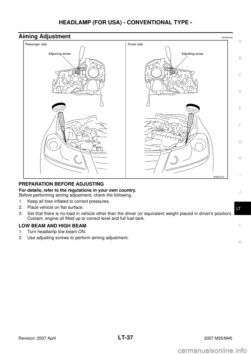
Aiming AdjustmentNKS003OG
PREPARATION BEFORE ADJUSTING
For details, refer to the regulations in your own country.
Before performing aiming adjustment, check the following.
1. Keep all tires inflated to correct pressures.
2. Place vehicle on flat surface.
3. Set that there is no-load in vehicle other than the driver (or equivalent weight placed in driver's position).
Coolant, engine oil filled up to correct level and full fuel tank.
LOW BEAM AND HIGH BEAM
1. Turn headlamp low beam ON.
2. Use adjusting screws to perform aiming adjustment.
SKIB4157E
Page 3523 of 4647

LT-72
HEADLAMP (FOR USA) - XENON TYPE -
Revision: 2007 April2007 M35/M45
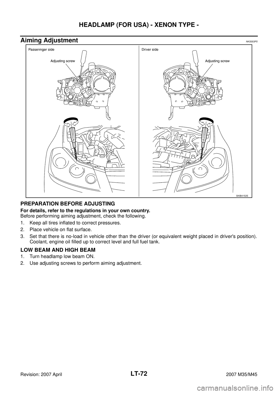
Aiming AdjustmentNKS003P5
PREPARATION BEFORE ADJUSTING
For details, refer to the regulations in your own country.
Before performing aiming adjustment, check the following.
1. Keep all tires inflated to correct pressures.
2. Place vehicle on flat surface.
3. Set that there is no-load in vehicle other than the driver (or equivalent weight placed in driver's position).
Coolant, engine oil filled up to correct level and full fuel tank.
LOW BEAM AND HIGH BEAM
1. Turn headlamp low beam ON.
2. Use adjusting screws to perform aiming adjustment.
SKIB4152E
Page 3766 of 4647

LU-1
ENGINE LUBRICATION SYSTEM
B ENGINE
CONTENTS
C
D
E
F
G
H
I
J
K
L
M
SECTION LU
A
LU
Revision: 2007 April2007 M35/M45
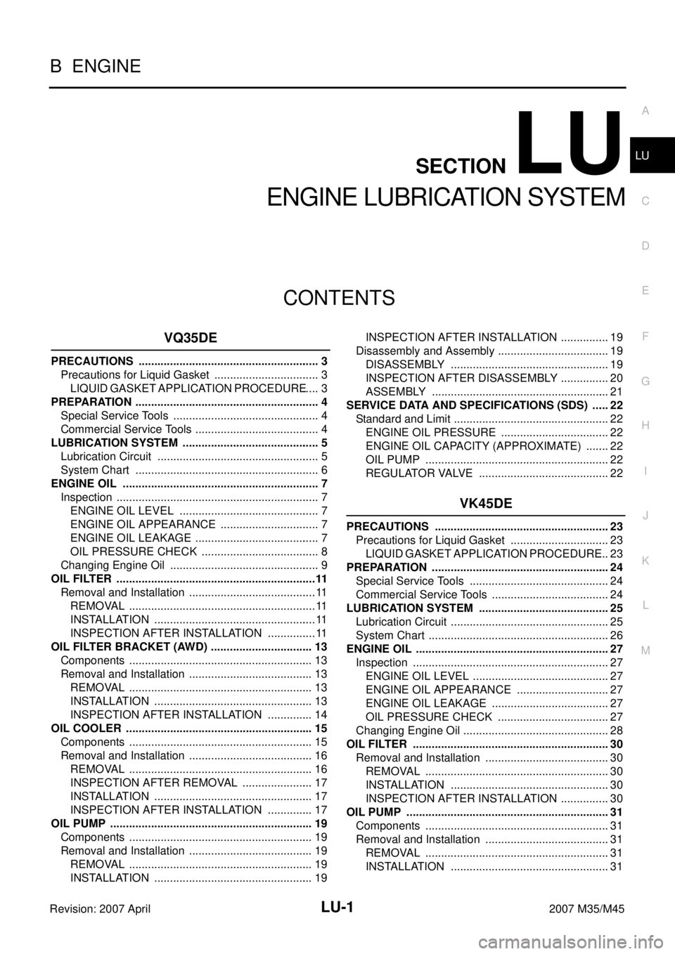
ENGINE LUBRICATION SYSTEM
VQ35DE
PRECAUTIONS .......................................................... 3
Precautions for Liquid Gasket .................................. 3
LIQUID GASKET APPLICATION PROCEDURE ..... 3
PREPARATION ........................................................... 4
Special Service Tools ............................................... 4
Commercial Service Tools ........................................ 4
LUBRICATION SYSTEM ............................................ 5
Lubrication Circuit .................................................... 5
System Chart ........................................................... 6
ENGINE OIL ............................................................... 7
Inspection ................................................................. 7
ENGINE OIL LEVEL ............................................. 7
ENGINE OIL APPEARANCE ................................ 7
ENGINE OIL LEAKAGE ........................................ 7
OIL PRESSURE CHECK ...................................... 8
Changing Engine Oil ................................................ 9
OIL FILTER ................................................................11
Removal and Installation ......................................... 11
REMOVAL ............................................................ 11
INSTALLATION .................................................... 11
INSPECTION AFTER INSTALLATION ................ 11
OIL FILTER BRACKET (AWD) ................................. 13
Components ........................................................... 13
Removal and Installation ........................................ 13
REMOVAL ........................................................... 13
INSTALLATION ................................................... 13
INSPECTION AFTER INSTALLATION ............... 14
OIL COOLER ............................................................ 15
Components ........................................................... 15
Removal and Installation ........................................ 16
REMOVAL ........................................................... 16
INSPECTION AFTER REMOVAL ....................... 17
INSTALLATION ................................................... 17
INSPECTION AFTER INSTALLATION ............... 17
OIL PUMP ................................................................. 19
Components ........................................................... 19
Removal and Installation ........................................ 19
REMOVAL ........................................................... 19
INSTALLATION ................................................... 19INSPECTION AFTER INSTALLATION ................ 19
Disassembly and Assembly .................................... 19
DISASSEMBLY ................................................... 19
INSPECTION AFTER DISASSEMBLY ................ 20
ASSEMBLY ......................................................... 21
SERVICE DATA AND SPECIFICATIONS (SDS) ...... 22
Standard and Limit .................................................. 22
ENGINE OIL PRESSURE ................................... 22
ENGINE OIL CAPACITY (APPROXIMATE) ........ 22
OIL PUMP ........................................................... 22
REGULATOR VALVE .......................................... 22
VK45DE
PRECAUTIONS ........................................................ 23
Precautions for Liquid Gasket ................................ 23
LIQUID GASKET APPLICATION PROCEDURE ... 23
PREPARATION ......................................................... 24
Special Service Tools ............................................. 24
Commercial Service Tools ...................................... 24
LUBRICATION SYSTEM .......................................... 25
Lubrication Circuit ................................................... 25
System Chart .......................................................... 26
ENGINE OIL .............................................................. 27
Inspection ............................................................... 27
ENGINE OIL LEVEL ............................................ 27
ENGINE OIL APPEARANCE .............................. 27
ENGINE OIL LEAKAGE ...................................... 27
OIL PRESSURE CHECK .................................... 27
Changing Engine Oil ............................................... 28
OIL FILTER ............................................................... 30
Removal and Installation ........................................ 30
REMOVAL ........................................................... 30
INSTALLATION ................................................... 30
INSPECTION AFTER INSTALLATION ................ 30
OIL PUMP ................................................................. 31
Components ........................................................... 31
Removal and Installation ........................................ 31
REMOVAL ........................................................... 31
INSTALLATION ................................................... 31
Page 3767 of 4647

LU-2Revision: 2007 April2007 M35/M45 INSPECTION AFTER INSTALLATION ................ 32
Disassembly and Assembly .................................... 32
DISASSEMBLY ................................................... 32
INSPECTION AFTER DISASSEMBLY ................ 32
ASSEMBLY ......................................................... 33SERVICE DATA AND SPECIFICATIONS (SDS) ...... 34
Standard and Limit .................................................. 34
ENGINE OIL PRESSURE .................................... 34
ENGINE OIL CAPACITY (APPROXIMATE) ........ 34
OIL PUMP ............................................................ 34
REGULATOR VALVE ........................................... 34
Page 3769 of 4647
![INFINITI M35 2007 Factory Service Manual LU-4
[VQ35DE]
PREPARATION
Revision: 2007 April2007 M35/M45
PREPARATIONPFP:00002
Special Service ToolsNBS004PS
The actual shapes of Kent-Moore tools may differ from those of special service tools illus INFINITI M35 2007 Factory Service Manual LU-4
[VQ35DE]
PREPARATION
Revision: 2007 April2007 M35/M45
PREPARATIONPFP:00002
Special Service ToolsNBS004PS
The actual shapes of Kent-Moore tools may differ from those of special service tools illus](/manual-img/42/57024/w960_57024-3768.png)
LU-4
[VQ35DE]
PREPARATION
Revision: 2007 April2007 M35/M45
PREPARATIONPFP:00002
Special Service ToolsNBS004PS
The actual shapes of Kent-Moore tools may differ from those of special service tools illustrated here.
Commercial Service ToolsNBS004PT
Tool number
(Kent-Moore No.)
Tool nameDescription
ST25051001
(J25695-1)
Oil pressure gaugeMeasuring oil pressure
Maximum measuring range: 2,452 kPa (25
kg-cm
2 , 356 psi)
ST25052000
(J25695-2)
HoseAdapting oil pressure gauge to oil pan (upper)
KV10115801
(J38956)
Oil filter wrenchRemoving and installing oil filter
a: 64.3 mm (2.531 in)
NT050
S-NT559
S-NT375
Tool nameDescription
Power toolsLoosening nuts and bolts
Deep socketRemoving and installing oil pressure switch
a: 26 mm (1.02 in)
PBIC0190E
PBIC2072E