Page 3831 of 4366

FRONT PROPELLER SHAFT PR-5
C E F
G H
I
J
K L
M A
B
PR
Revision: 2006 July 2007 FX35/FX45
Removal and InstallationNDS000AV
REMOVAL
1. Remove the front and rear engine undercover with a power tool.
2. Remove the front cross bar with a power tool. Refer to FSU-6, "
FRONT SUSPENSION ASSEMBLY" .
3. Remove the exhaust front tube bracket with a power tool. Refer to EX-3, "
EXHAUST SYSTEM" .
4. Disconnect the heated oxygen sensor harness connector.
5. Remove the exhaust front tube mounting nuts with a power tool. Refer to EX-3, "
EXHAUST SYSTEM" .
6. Remove the right bank three way catalyst with a power tool. Refer to EM-26, "
Removal and Installation"
(VQ35DE), EM-183, "Removal and Installation" (VK45DE).
7. Remove the power steering piping mounting bolts. Refer to PS-
41, "HYDRAULIC LINE" .
8. Remove the power steering gear box fixing bolts to secure work- ing area for removal of propeller shaft. Refer to PS-18, "
POWER
STEERING GEAR AND LINKAGE" .
CAUTION:
Be careful not to damage the steering gear box piping dur-
ing removal.
9. Put matching marks onto propeller shaft flange yoke and final drive companion flange.
CAUTION:
For matching mark, use paint. Do not damage propeller
shaft flange and companion flange.
10. Remove the propeller shaft fixing bolts.
11. Set the transmission jack at the transfer, remove rear engine mounting bolts, and then lower transmission jack about 40 - 50
mm (0.16 - 0.21 in).
12. Remove propeller shaft from the front final drive and transfer.
INSPECTION
�Inspect propeller shaft runout at measuring point. If runout
exceeds specifications, replace propeller shaft assembly. For
measuring point, refer to PR-4, "
Propeller Shaft Runout Measur-
ing Point" .
SDIA1516E
SDIA1517E
SDIA1518E
Propeller shaft runout limit : 0.8 mm (0.031 in)
SPD106
Page 3832 of 4366
PR-6
FRONT PROPELLER SHAFT
Revision: 2006 July 2007 FX35/FX45
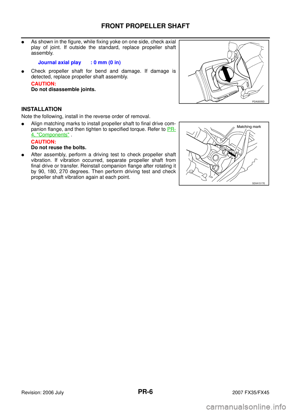
�As shown in the figure, while fixing yoke on one side, check axial
play of joint. If outside the standard, replace propeller shaft
assembly.
�Check propeller shaft for bend and damage. If damage is
detected, replace propeller shaft assembly.
CAUTION:
Do not disassemble joints.
INSTALLATION
Note the following, install in the reverse order of removal.
�Align matching marks to install propeller shaft to final drive com-
panion flange, and then tighten to specified torque. Refer to PR-
4, "Components" .
CAUTION:
Do not reuse the bolts.
�After assembly, perform a driving test to check propeller shaft
vibration. If vibration occurred, separate propeller shaft from
final drive or transfer. Reinstall companion flange after rotating it
by 90, 180, 270 degrees. Then perform driving test and check
propeller shaft vibration again at each point. Journal axial play : 0 mm (0 in)
PDA0005D
SDIA1517E
Page 3833 of 4366

REAR PROPELLER SHAFT PR-7
C E F
G H
I
J
K L
M A
B
PR
Revision: 2006 July 2007 FX35/FX45
REAR PROPELLER SHAFTPFP:37000
On-Vehicle InspectionNDS000AW
APPEARANCE AND NOISE INSPECTION
�Check the propeller shaft tube surface for dents or cracks. If damaged, replace propeller shaft assembly.
�If center bearing is noisy or damaged, replace center bearing.
PROPELLER SHAFT VIBRATION
If vibration is present at high speed, inspect propeller shaft runout first.
1. Measure propeller shaft runout at runout measuring points by rotating final drive companion flange with hands. For measuring
point, refer to PR-4, "
Propeller Shaft Runout Measuring Point" .
2. If runout still exceeds specifications, separate propeller shaft at final drive companion flange; then rotate companion flange 60,
120, 180, 240, 300 degrees and install propeller shaft.
3. Check runout again. If runout still exceeds specifications, replace propeller shaft assembly.
4. Check the vibration by driving vehicle.
Propeller Shaft Runout Measuring Point
� 2WD models (3S80A-1VL107 type)
� AWD models (3F80A-1VL107 type) Propeller shaft runout limit : 0.8 mm (0.031 in)
SDIA1781E
Dimension A: 192 mm (7.56 in)
B: 190 mm (7.48 in)
C: 185 mm (7.28 in)
SDIA1581E
Dimension A: 162 mm (6.38 in) B: 245 mm (9.65 in)
C: 185 mm (7.28 in)
SDIA1779E
Page 3835 of 4366

REAR PROPELLER SHAFT PR-9
C E F
G H
I
J
K L
M A
B
PR
Revision: 2006 July 2007 FX35/FX45
Removal and InstallationNDS000AY
REMOVAL
1. Move the A/T select lever to N position and release the parking brake.
2. Remove the tunnel stay with power tool. Refer to RSU-5, "
REAR
SUSPENSION ASSEMBLY" .
3. Remove the center muffler with power tool. Refer to EX-3,
"EXHAUST SYSTEM" .
4. Loosen mounting nuts of center bearing mounting brackets with power tool.
CAUTION:
Tighten mounting nuts temporarily.
5. For 2WD models
�Put matching marks on propeller shaft rebro joint with final
drive companion flange.
CAUTION:
For matching mark, use paint. Do not damage propeller
shaft and companion flange.
For AWD models
�Put matching marks on propeller shaft flange yoke with trans-
fer companion flange and on rebro joint with final drive com-
panion flange.
CAUTION:
For matching mark, use paint. Do not damage propeller shaft flange yoke, rebro joint and com-
panion flanges.
6. Remove propeller shaft fixing bolts and nuts.
7. Remove center bearing mounting bracket fixing nuts.
8. Remove propeller shaft.
CAUTION:
If constant velocity joint was bent during propeller shaft assembly removal, installation, or trans-
portation, its boot may be damaged. Wrap boot interference area to metal part with shop cloth or
rubber to protect boot from breakage.
PDIA0744E
PDIA0402E
PDIA0470E
Page 3837 of 4366

REAR PROPELLER SHAFT PR-11
C E F
G H
I
J
K L
M A
B
PR
Revision: 2006 July 2007 FX35/FX45
INSTALLATION
Note the following, and install in the reverse order of removal.
CAUTION:
Avoid damaging the rebro joint boot, protect it with a shop towel or equivalent.
�Align matching marks to install propeller shaft to final drive and transfer (AWD models only) companion
flanges, and then tighten to specified torque. Refer to PR-8, "
Components" .
�Install center bearing mounting bracket (Upper) with its arrow
mark facing forward.
�Adjust position of mounting bracket sliding back and forth to pre-
vent play in thrust direction of center bearing insulator. Install
bracket to vehicle.
�After assembly, perform a driving test to check propeller shaft
vibration. If vibration occurred, separate propeller shaft from
final drive. Reinstall companion flange after rotating it by 60,
120, 180, 240, 300 degrees. Then perform driving test and
check propeller shaft vibration again at each point.
�If propeller shaft or final drive has been replaced, connect them
as follows:
1. Install the propeller shaft while aligning its matching mark A with the matching mark B on the joint as close as possible.
2. Tighten the joint bolts to the specified torque. Refer to PR-8,
"Components" .
CAUTION:
Do not reuse the bolts, nuts and washers.
PDIA0017E
SDIA2049E
Page 3840 of 4366

Revision: 2006 July 2007 FX35/FX45
SERVICE DATA AND SPECIFICATIONS (SDS)PFP:00030
General SpecificationsNDS000B0
2WD MODELS
AW D M OD E LS
Journal Axal Pl")
PR-14
SERVICE DATA AND SPECIFICATIONS (SDS)
Revision: 2006 July 2007 FX35/FX45
SERVICE DATA AND SPECIFICATIONS (SDS)PFP:00030
General SpecificationsNDS000B0
2WD MODELS
AW D M OD E LS
Journal Axal PlayNDS000B1
Propeller Shaft RunoutNDS000B2
Applied model VQ35DE
Propeller shaft model 3S80A-1VL107
Number of joints 3
Coupling method with transmission Sleeve type
Coupling method with rear final drive Rebro joint type
Shaft length 1st (Spider to spider) 795 mm (31.30 in)
2nd (Spider to rebro joint center) 681 mm (35.51 in)
Shaft outer diameter 1st 82.6 mm (3.25 in)
2nd 82.6 mm (3.25 in)
Applied model VQ35DE VK45DE
Front Propeller shaft model 2S56A Number of joints 2
Coupling method with transfer Sleeve type
Coupling method with front final drive Flange type
Shaft length (Spider to spider) 763 mm (30.04 in)
Shaft outer diameter 42.7 mm (1.68 in)
Rear Propeller shaft model 3F80A-1VL107 Number of joints 3
Coupling method with transfer Flange type
Coupling method with rear final drive Rebro joint type
Shaft length 1st (Spider to spider) 399 mm (15.71 in)
2nd (Spider to rebro joint center) 753 mm (29.65 in)
Shaft outer
diameter 1st 82.6 mm (3.25 in)
2nd 82.6 mm (3.25 in)
Model Front propeller shaft Rear propeller shaft
2S56A 3S80A-1VL107 3F80A-1VL107
Journal axial play 0 mm (0 in)
Model Front propeller shaft Rear propeller shaft
2S56A 3S80A-1VL107 3F80A-1VL107
Propeller shaft runout limit 0.8 mm (0.031 in)
Page 3896 of 4366
RAX-10
REAR DRIVE SHAFT
Revision: 2006 July 2007 FX35/FX45
Disassembly and AssemblyNDS000CL
COMPONENTS
DISASSEMBLY
Final Drive Side
1. Press shaft in a vice.
CAUTION:
When retaining drive shaft in a vise, always use copper or aluminum plates between vise and
shaft.
2. Remove boot bands.
3. If plug needs to be removed, move boot to wheel side, and drive it out with a plastic hammer.
4. Remove stopper ring with a flat-bladed screwdriver, and pull out housing.
1. Plug 2. Housing 3. Snap ring
4. Ball cage/Steel ball/Inner race assembly 5. Stopper ring 6. Boot band
7. Boot 8. Shaft 9. Circular clip
10. Joint sub-assembly
Refer to GI-11, "
Components" , for the symbols in the figure.
: Apply Nissan genuine grease or equivalent.
PDIA1229E
SRA249A
Page 3898 of 4366

RAX-12
REAR DRIVE SHAFT
Revision: 2006 July 2007 FX35/FX45
CAUTION:
If there are any irregular conditions in the component, replace with a new set of housing, ball
cage, steel ball and inner race.
ASSEMBLY
Final Drive Side
1. If plug has been removed, use a drift (SST) to press in a new one.
NOTE:
Discard old plug; replace with new one.
2. Wind serrated part of shaft with tape. Install boot band and boot to shaft. Be careful not to damage boot.
NOTE:
Discard old boot band and boot; replace with each new one.
3. Remove protective tape wound around serrated part of shaft.
4. Install ball cage/steel ball/inner race assembly to shaft, and secure them tightly with a snap ring.
NOTE:
Discard old snap ring; replace with new one.
5. Insert the amount of grease (NISSAN genuine grease or equiva- lent) onto housing (* point) to the quantity mentioned below, and
install it to shaft.
6. Install stopper ring to housing.
7. After installed, pull shaft to check engagement between joint sub-assembly and stopper ring.
SDIA1153E
SFA800
SDIA1125E
Grease amount
VK45DE : 175 − 195 g (6.17 − 6.88 oz)
VQ35DE : 124 − 134 g (4.37 − 4.73 oz)
RAC0678D