Page 3879 of 4366

POWER STEERING OIL PUMP PS-39
C
D E
F
H I
J
K L
M A
B
PS
Revision: 2006 July 2007 FX35/FX45
ASSEMBLY
NOTE:
Fix oil pump in vise as vise occasion demands.
CAUTION:
When retaining drive shaft assembly in a vise, always use copper or aluminum plates between vise
and shaft.
1. Apply recommended grease to oil seal lips (1). Apply recom- mended fluid to around oil seal, and then install oil seal to body
assembly.
2. Apply recommended fluid to drive shaft assembly and press drive shaft assembly into body assembly with suitable tool, then
install snap ring.
3. Apply recommended fluid to O-ring and Install O-ring into body assembly.
4. Install side plate to body assembly.
5. Install lock pin into lock pin hole, and install cam-ring as shown in the figure.
�When installing cam-ring, turn carved face with a letter (E) of
it to rear cover.
CAUTION:
Do not confuse the assembling direction of cam ring. If
cam ring is installed facing the incorrect direction, it may
cause pump operation malfunction.
6. Install rotor to body assembly.
SGIA1150E
SGIA0422E
SGIA0591E
Page 3880 of 4366
PS-40
POWER STEERING OIL PUMP
Revision: 2006 July 2007 FX35/FX45
�When installing rotor, turn punch mark face on rotor to body
assembly.
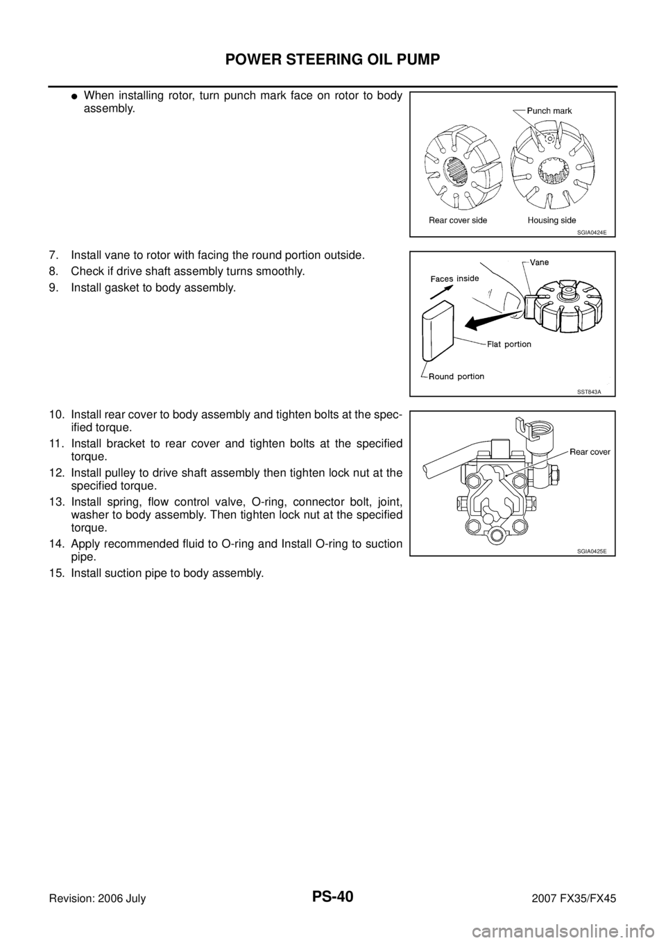
7. Install vane to rotor with facing the round portion outside.
8. Check if drive shaft assembly turns smoothly.
9. Install gasket to body assembly.
10. Install rear cover to body assembly and tighten bolts at the spec- ified torque.
11. Install bracket to rear cover and tighten bolts at the specified torque.
12. Install pulley to drive shaft assembly then tighten lock nut at the specified torque.
13. Install spring, flow control valve, O-ring, connector bolt, joint, washer to body assembly. Then tighten lock nut at the specified
torque.
14. Apply recommended fluid to O-ring and Install O-ring to suction pipe.
15. Install suction pipe to body assembly.
SGIA0424E
SST843A
SGIA0425E
Page 3881 of 4366
HYDRAULIC LINE PS-41
C
D E
F
H I
J
K L
M A
B
PS
Revision: 2006 July 2007 FX35/FX45
HYDRAULIC LINEPFP:49721
ComponentsNGS000CA
VQ35DE 2WD MODEL
SGIA1681E
1. Reservoir tank 2. Reservoir tank bracket 3. Suction hose
4. High pressure hose 5. Power steering oil pump 6. Steering gear assembly
7. Oil cooler 8. Low pressure piping 9. High pressure piping
10. O-ring 11. Copper washer 12. Eye-bolt
13. Eye-joint (assembled to high pres- sure side hose) 14. Pressure sensor
Refer to GI-11, "
Components" and the followings for the symbols in the figure.
: Apply power steering fluid.
Page 3882 of 4366
PS-42
HYDRAULIC LINE
Revision: 2006 July 2007 FX35/FX45
VQ35DE AWD MODEL
SGIA1682E
1. Reservoir tank 2. Reservoir tank bracket 3. Suction hose
4. High pressure hose 5. Power steering oil pump 6. Steering gear assembly
7. Oil cooler 8. Low pressure piping 9. High pressure piping
10. O-ring 11. Copper washer 12. Eye-bolt
13. Eye-joint (assembled to high pres- sure side hose) 14. Pressure sensor
Refer to GI-11, "
Components" and the followings for the symbols in the figure.
: Apply power steering fluid.
Page 3883 of 4366
HYDRAULIC LINE PS-43
C
D E
F
H I
J
K L
M A
B
PS
Revision: 2006 July 2007 FX35/FX45
VK45DE AWD MODEL
SGIA1683E
1. Reservoir tank 2. Suction hose 3. High pressure hose
4. Oil cooler 5. Pressure sensor 6. Steering gear assembly
7. Low pressure piping 8. High pressure piping 9. O-ring
10. Reservoir tack bracket 11. Eye-joint (assembled to high pres- sure side hose) 12. Eye-bolt
Refer to GI-11, "
Components" and the followings for the symbols in the figure.
: Apply power steering fluid.
Page 3886 of 4366
PS-46
SERVICE DATA AND SPECIFICATIONS (SDS)
Revision: 2006 July 2007 FX35/FX45
Steering GearNGS000CI
Oil PumpNGS000CJ
Steering FluidNGS000CK
Tie-rod length “L” 135.2 mm (5.32 in)
SGIA0167E
Steering gear model PR26AM
Rack neutral position, dimension “L” (rack stroke) 67.0 mm (2.64 in)
Rack sliding force At the neutral point:
Range within ± 11.5 mm
( ± 0.453 in) from the neutral
position
(in power ON) Area average value 147
− 211 N (15 − 21.5 kg, 33 − 47 lb)
Allowable variation 98 N (10 kg, 22 lb) or less
Whole area (in power OFF) Peak value 294 N (30 kg, 66 lb) or less
Allowable variation 147 N (15 kg, 33 lb) or less
SGIA0629J
Oil pump relief hydraulic pressure 9,900 − 10,700 kPa (101 − 109.1 kg/cm2 , 1436 − 1552 psi)
Fluid capacity
Approx. 1.0 (1-1/8 US qt, 7/8 Imp qt)
Page 4205 of 4366

TF-1
TRANSFER
D DRIVELINE/AXLE
CONTENTS
C E F
G H
I
J
K L
M
SECTION
A
B
TF
Revision: 2006 July 2007 FX35/FX45
TRANSFER
PRECAUTIONS .......................................................... 3
Precautions for Supplemental Restraint System
(SRS) “AIR BAG” and “SEAT BELT PRE-TEN-
SIONER” ............................................................. ..... 3
Precautions ......................................................... ..... 3
Service Notice or Precautions ............................. ..... 4
PREPARATION ...................................................... ..... 5
Special Service Tools .......................................... ..... 5
Commercial Service Tools ................................... ..... 7
NOISE, VIBRATION AND HARSHNESS (NVH)
TROUBLESHOOTING ........................................... ..... 8
NVH Troubleshooting Chart ................................ ..... 8
TRANSFER FLUID ................................................ ..... 9
Replacement ....................................................... ..... 9
DRAINING ........................................................ ..... 9
FILLING ............................................................ ..... 9
Inspection ............................................................ ..... 9
FLUID LEAKAGE AND FLUID LEVEL ............. ..... 9
AWD SYSTEM ....................................................... ... 10
Power Transfer Diagram ..................................... ... 10
System Description ............................................. ... 10
DESCRIPTION ................................................. ... 10
ELECTRIC CONTROLLED COUPLING .......... .... 11
AWD CONTROL UNIT ..................................... .... 11
AWD WARNING LAMP .................................... ... 12
System Diagram .................................................. ... 12
COMPONENTS FUNCTION DESCRIPTION .. ... 13
CAN Communication ........................................... ... 13
SYSTEM DESCRIPTION ................................. ... 13
TROUBLE DIAGNOSIS ......................................... ... 14
Fail-Safe Function ............................................... ... 14
How to Perform Trouble Diagnosis ..................... ... 14
BASIC CONCEPT ............................................ ... 14
Location of Electrical Parts .................................. ... 15
Circuit Diagram ................................................... ... 16
Wiring Diagram — AWD — ................................. ... 17
Trouble Diagnosis Chart for Symptoms .............. ... 20
AWD Control Unit Input/Output Signal Reference
Values ................................................................. ... 21 AWD CONTROL UNIT INSPECTION TABLE ..
... 21
CONSULT-II Function (ALL MODE AWD/4WD) .. ... 22
FUNCTION ....................................................... ... 22
CONSULT-II SETTING PROCEDURE ............. ... 22
SELF-DIAG RESULT MODE ............................ ... 22
DATA MONITOR MODE ................................... ... 24
ACTIVE TEST MODE ...................................... ... 25
AWD CONTROL UNIT PART NUMBER .......... ... 25
TROUBLE DIAGNOSIS FOR SYSTEM ................. ... 26
Power Supply Circuit for AWD Control Unit ......... ... 26
CONSULT-II REFERENCE VALUE IN DATA
MONITOR MODE ............................................. ... 26
DIAGNOSTIC PROCEDURE ........................... ... 26
AWD Control Unit ................................................ ... 27
DIAGNOSTIC PROCEDURE ........................... ... 27
ABS System ........................................................ ... 27
DIAGNOSTIC PROCEDURE ........................... ... 27
AWD Solenoid ..................................................... ... 28
CONSULT-II REFERENCE VALUE IN DATA
MONITOR MODE ............................................. ... 28
DIAGNOSTIC PROCEDURE ........................... ... 28
COMPONENT INSPECTION ........................... ... 30
AWD Actuator Relay ............................................ ... 31
CONSULT-II REFERENCE VALUE IN DATA
MONITOR MODE ............................................. ... 31
DIAGNOSTIC PROCEDURE ........................... ... 31
Engine Control Signal .......................................... ... 32
DIAGNOSTIC PROCEDURE ........................... ... 32
CAN Communication Line ................................... ... 32
DIAGNOSTIC PROCEDURE ........................... ... 32
TROUBLE DIAGNOSIS FOR SYMPTOMS ........... ... 33
AWD Warning Lamp Does Not Turn ON When The
Ignition Switch Is Turned to ON ........................... ... 33
DIAGNOSTIC PROCEDURE ........................... ... 33
AWD Warning Lamp Does Not Turn OFF Several
Seconds after Engine Started .............................. ... 33
DIAGNOSTIC PROCEDURE ........................... ... 33
Heavy Tight-Corner Braking Symptom Occurs
When The Vehicle Is Driven and The Steering Wheel
Is Turned Fully to Either Side after The Engine Is


Revision: 2006 July 2007 FX35/FX45
Steering GearNGS000CI
Oil PumpNGS000CJ
Steering FluidNGS000CK
Tie-rod length “L” 135.2 mm (5.32 in)
SGIA0167E
Steeri")