Page 3985 of 4366

REAR SUSPENSION MEMBER RSU-17
C
D
F
G H
I
J
K L
M A
B
RSU
Revision: 2006 July 2007 FX35/FX45
REAR SUSPENSION MEMBERPFP:55501
Removal and InstallationNES000GF
REMOVAL
1. Remove tires from vehicle with power tool.
2. Remove brake caliper with power tool. Hang it in a place where it will not interfere with work. Refer to BR-
25, "REAR DISC BRAKE" .
NOTE:
Avoid depressing brake pedal while brake caliper is removed.
3. Remove wheel sensor from rear final drive, then remove wheel sensor harness from rear suspension member. Refer to BRC-57, "
WHEEL SENSORS" .
4. Remove height sensor harness from rear suspension member (if equipped).
5. Remove center muffler and main muffler. Refer to EX-3, "
EXHAUST SYSTEM" .
6. Remove stabilizer bar. Refer to RSU-16, "
Removal and Installation" .
7. Remove rear drive shaft. Refer to RAX-9, "
REAR DRIVE SHAFT" .
8. Remove propeller shaft. Refer to PR-7, "
REAR PROPELLER SHAFT" .
9. Remove rear final drive. Refer to RFD-16, "
Removal and Installation" .
10. Separate attachments between parking brake cable and vehicle and rear suspension member. Refer to PB-4, "
PARKING BRAKE CONTROL" .
11. Remove rear lower link and coil spring. Refer to RSU-14, "
Removal and Installation" .
12. Remove fixing bolt in lower side of shock absorber with power tool.
13. Set jack under rear suspension member.
14. Remove fixing bolts and nuts of tunnel stay and member stay with power tool, then remove those parts from vehicle and rear suspension member.
15. Remove fixing bolts and nuts of rear pin stay with power tool and then remove rear pin stay from vehicle and rear suspension member.
16. Slowly lowering jack, then remove rear suspension member, suspension arm, radius rod, front lower link and axle from vehicle as a unit.
17. Remove fixing bolts and nuts with power tool, then remove suspension arm, front lower link, and radius rod from rear suspension member.
INSPECTION AFTER REMOVAL
Check rear suspension member for deformation, cracks, and other damage and replace if necessary.
INSTALLATION
�Refer to RSU-7, "Removal and installation" , for tightening torque. Install in the reverse order of removal.
NOTE:
Refer to component parts location and do not reuse non-reusable parts.
�Perform final tightening of installation position of links (rubber bushing) under unladen conditions with tires
on level ground. Check wheel alignment. Refer to RSU-5, "
Wheel Alignment Inspection" .
�After adjusting wheel alignment, adjust neutral position of steering angle sensor. Refer to BRC-6, "Adjust-
ment of Steering Angle Sensor Neutral Position" .
Page 4188 of 4366
SRS-42
DRIVER AIR BAG MODULE
Revision: 2006 July 2007 FX35/FX45
DRIVER AIR BAG MODULEPFP:K8510
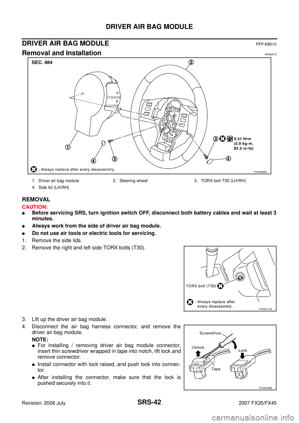
Removal and InstallationNHS0007L
REMOVAL
CAUTION:
�Before servicing SRS, turn ignition switch OFF, disconnect both battery cables and wait at least 3
minutes.
�Always work from the side of driver air bag module.
�Do not use air tools or electric tools for servicing.
1. Remove the side lids.
2. Remove the right and left side TORX bolts (T30).
3. Lift up the driver air bag module.
4. Disconnect the air bag harness connector, and remove the driver air bag module.
NOTE:
�For installing / removing driver air bag module connector,
insert thin screwdriver wrapped in tape into notch, lift lock and
remove connector.
�Install connector with lock raised, and push lock into connec-
tor.
�After installing the connector, make sure that the lock is
pushed securely into it.
PHIA0685E
1. Driver air bag module 2. Steering wheel 3. TORX bolt T30 (LH/RH)
4. Side lid (LH/RH)
PHIA0714E
PHIA0308E
Page 4189 of 4366

DRIVER AIR BAG MODULE SRS-43
C
D E
F
G
I
J
K L
M A
B
SRS
Revision: 2006 July 2007 FX35/FX45
CAUTION:
�Always place driver air bag module with pad side facing
upward.
�Do not insert any foreign objects (screwdriver, etc.) into
driver air bag module.
�Do not disassemble driver air bag module.
�Do not use old bolts after removal; replace with new bolts.
�Do not expose the driver air bag module to temperatures
exceeding 90 °C (194 °F).
�Replace driver air bag module if it has been dropped or sus-
tained an impact.
�Do not allow oil, grease or water to come in contact with the
driver air bag module.
INSTALLATION
Install in the reverse order of removal.
CAUTION:
�Fix the air bag module harness (shown as A in the figure) to
the harness fixing hook (shown as B in the figure).
�Be careful not to damage the harness while installing.
�Tighten the special bolts after exactly adjusting the centers of fixing holes on the air bag module
side and the steering wheel side. If the holes are misaligned, the bolt threads are damaged and the
module is not installed securely.
�After the work is completed, make sure no system malfunction is detected by air bag warning
lamp.
�In case that malfunction is detected by the air bag warning lamp, reset by the self-diagnosis func-
tion and delete the memory by CONSOULT–II.
�In case that malunction is still detected after the above operation, peform self-diagnosis to repair
malfunctions. Refer to Refer to SRS-20, "
SRS Operation Check" .
PHIA0320E
SBF814E
PHIA0885J
Page 4202 of 4366
SRS-56
COLLISION DIAGNOSIS
Revision: 2006 July 2007 FX35/FX45
Steering wheel [same text as in current manual]
Spiral cable If the Driver airbag has deployed: REPLACE the spiral cable. If the Driver airbag has not deployed:
[same text as in current manual]
Harness and con-
nectors 1. Check connectors for poor connection, damage, and terminals for deformities.
2. Check harness for binding, chafing, cuts, or deformities.
3. If no damage is found, reinstall the harness and connectors.
4. If damaged—REPLACE damaged section of harness. Do not repair, splice or modify any SRS harness.
Instrument panel 1. Visually check instrument panel for damage. 2. If no damage is found, reinstall the instrument panel.
3. If damaged—REPLACE the instrument panel with bolts.
Part SRS is activated SRS is NOT activated
![INFINITI FX35 2007 Service Manual SRS-56
COLLISION DIAGNOSIS
Revision: 2006 July 2007 FX35/FX45
Steering wheel [same text as in current manual]
Spiral cable If the Driver airbag ha](/manual-img/42/57018/w960_57018-4201.png "INFINITI FX35 2007 Service Manual SRS-56
COLLISION DIAGNOSIS
Revision: 2006 July 2007 FX35/FX45
Steering wheel [same text as in current manual]
Spiral cable If the Driver airbag ha")