Page 3087 of 4366

FAX-1
FRONT AXLE
D DRIVELINE/AXLE
CONTENTS
C E F
G H
I
J
K L
M
SECTION
A
B
FA X
Revision: 2006 July 2007 FX35/FX45
FRONT AXLE
2WD
PREPARATION ........................................................... 2
Special Service Tools .......................................... ..... 2
Commercial Service Tools ................................... ..... 2
NOISE, VIBRATION AND HARSHNESS (NVH)
TROUBLESHOOTING ........................................... ..... 3
NVH Troubleshooting Chart ................................ ..... 3
FRONT WHEEL HUB AND KNUCKLE ................. ..... 4
On-Vehicle Inspection ......................................... ..... 4
WHEEL BEARING INSPECTION .................... ..... 4
Removal and Installation ..................................... ..... 4
COMPONENTS ............................................... ..... 4
REMOVAL ........................................................ ..... 4
INSPECTION AFTER REMOVAL .................... ..... 5
INSTALLATION ................................................ ..... 5
SERVICE DATA AND SPECIFICATIONS (SDS) ... ..... 6
Wheel Bearing ..................................................... ..... 6
AWD
PRECAUTIONS ..................................................... ..... 7
Caution ................................................................ ..... 7
PREPARATION ...................................................... ..... 8
Special Service Tools .......................................... ..... 8
Commercial Service Tools ................................... ..... 8
NOISE, VIBRATION AND HARSHNESS (NVH)
TROUBLESHOOTING ........................................... ..... 9
NVH Troubleshooting Chart ................................ ..... 9
FRONT WHEEL HUB AND KNUCKLE ................. ... 10
On-Vehicle Inspection ......................................... ... 10 WHEEL BEARING INSPECTION ....................
... 10
Removal and Installation ..................................... ... 10
COMPONENTS ................................................ ... 10
REMOVAL ........................................................ ... 10
INSPECTION AFTER REMOVAL .................... ... 11
INSTALLATION ................................................ ... 11
FRONT DRIVE SHAFT .......................................... ... 12
On-Vehicle Inspection .......................................... ... 12
DRIVE SHAFT BOOT REPLACEMENT ........... ... 12
Removal and Installation (Left Side) .................... ... 15
COMPONENTS ................................................ ... 15
REMOVAL ........................................................ ... 15
INSPECTION AFTER REMOVAL .................... ... 15
INSTALLATION ................................................ ... 15
Removal and Installation (Right Side) ................. ... 16
COMPONENTS ................................................ ... 16
REMOVAL ........................................................ ... 16
INSPECTION AFTER REMOVAL .................... ... 16
INSTALLATION ................................................ ... 17
Disassembly and Assembly (Left Side) ............... ... 18
COMPONENTS ................................................ ... 18
DISASSEMBLY ................................................ ... 18
INSPECTION AFTER DISASSEMBLY ............. ... 19
ASSEMBLY ...................................................... ... 20
Disassembly and Assembly (Right Side) ............. ... 22
COMPONENTS ................................................ ... 22
DISASSEMBLY ................................................ ... 22
INSPECTION AFTER DISASSEMBLY ............. ... 23
ASSEMBLY ...................................................... ... 24
SERVICE DATA AND SPECIFICATIONS (SDS) ... ... 26
Wheel Bearing ..................................................... ... 26
Drive Shaft ........................................................... ... 26
Page 3088 of 4366
FAX-2
[2WD]
PREPARATION
Revision: 2006 July 2007 FX35/FX45
[2WD]PREPARATIONPFP:00002
Special Service Tools NDS000BU
The actual shapes of Kent-Moore tools may differ from those of special service tools illustrated here.
Commercial Service ToolsNDS000BV
Tool number
(Kent-Moore No.)
Tool name Description
HT72520000
(J −25730-A)
Ball joint remover
a: 33 mm (1.30 in)
b: 50 mm (1.97 in)
r: 11.5 mm (0.453 in)
�Removing steering outer socket
�Removing transverse link
NT546
Tool name Description
Power tool Loosening bolts and nuts
PBIC0190E
Page 3091 of 4366
![INFINITI FX35 2007 Service Manual FRONT WHEEL HUB AND KNUCKLE FAX-5
[2WD]
C E F
G H
I
J
K L
M A
B
FA X
Revision: 2006 July 2007 FX35/FX45
6. Use a ball joint remover (SST) to remove steering outer socket
from steering knu](/manual-img/42/57018/w960_57018-3090.png "INFINITI FX35 2007 Service Manual FRONT WHEEL HUB AND KNUCKLE FAX-5
[2WD]
C E F
G H
I
J
K L
M A
B
FA X
Revision: 2006 July 2007 FX35/FX45
6. Use a ball joint remover (SST) to remove steering outer socket
from steering knu")
FRONT WHEEL HUB AND KNUCKLE FAX-5
[2WD]
C E F
G H
I
J
K L
M A
B
FA X
Revision: 2006 July 2007 FX35/FX45
6. Use a ball joint remover (SST) to remove steering outer socket
from steering knuckle. Be careful not to damage ball joint boot.
CAUTION:
Tighten temporarily mounting nut to prevent damage to
threads and to prevent ball joint remover (SST) from com-
ing off.
7. Remove cotter pin at transverse link, then loosen mounting nut.
8. Use a ball joint remover (SST) to remove transverse link from steering knuckle. Be careful not to damage ball joint boot.
CAUTION:
Tighten temporarily mounting nut to prevent damage to
threads and to prevent ball joint remover (SST) from com-
ing off.
9. Remove fixing bolts and nuts between strut assembly and steer- ing knuckle with power tool.
10. Remove steering knuckle from vehicle.
11. Remove fixing bolts between steering knuckle and wheel hub and bearing assembly with power tool.
12. Remove splash guard and wheel hub and bearing assembly from steering knuckle.
INSPECTION AFTER REMOVAL
Check for deformity, cracks and damage on each parts, replace if necessary.
Ball Joint Inspection
�Check for boot breakage, axial looseness, and torque of transverse link and steering outer socket ball
joint. Refer to FSU-14, "
TRANSVERSE LINK" , PS-18, "POWER STEERING GEAR AND LINKAGE" .
INSTALLATION
�Refer to FAX-4, "Removal and Installation" for tightening torque. Install in the reverse order of removal.
NOTE:
Refer to component parts location and do not reuse non-reusable parts.
�After removing/installing or replacing axle components, check wheel alignment. Refer to FSU-6, "Wheel
Alignment Inspection" .
�After adjusting wheel alignment, adjust neutral position of steering angle sensor. Refer to BRC-6, "Adjust-
ment of Steering Angle Sensor Neutral Position" .
�Check the following item after service
–Installation condition of wheel sensor harness
SDIA1434E
SDIA1435E
Page 3092 of 4366
FAX-6
[2WD]
SERVICE DATA AND SPECIFICATIONS (SDS)
Revision: 2006 July 2007 FX35/FX45
SERVICE DATA AND SPECIFICATIONS (SDS)PFP:00030
Wheel BearingNDS000BZ
Axial end play0.05 mm (0.002 in) or less
Page 3093 of 4366
PRECAUTIONS FAX-7
[AWD]
C E F
G H
I
J
K L
M A
B
FA X
Revision: 2006 July 2007 FX35/FX45
[AWD]PRECAUTIONSPFP:00001
CautionNDS000C0
Observe the following precautions when disassembling and servicing drive shaft.
�Joint sub-assembly does not disassemble because it is non-overhaul parts.
�Perform work in a location which is as dust-free as possible.
�Before disassembling and servicing, clean the outside of parts.
�Prevention of the entry of foreign objects must be taken into account during disassembly of the service
location.
�Disassembled parts must be carefully reassembled in the correct order. If work is interrupted, a clean
cover must be placed over parts.
�Paper shop cloths must be used. Fabric shop cloths must not be used because of the danger of lint adher-
ing to parts.
�Disassembled parts (except for rubber parts) should be cleaned with kerosene which shall be removed by
blowing with air or wiping with paper shop cloths.
Page 3094 of 4366
FAX-8
[AWD]
PREPARATION
Revision: 2006 July 2007 FX35/FX45
PREPARATIONPFP:00002
Special Service Tools NDS000C1
The actual shapes of Kent-Moore tools may differ from those of special service tools illustrated here.
Commercial Service ToolsNDS000C2
Tool number
(Kent-Moore No.)
Tool name Description
HT72520000
(J −25730-A)
Ball joint remover
a: 33 mm (1.30 in)
b: 50 mm (1.97 in)
r: 11.5 mm (0.453 in)
�Removing steering outer socket
�Removing transverse link
KV40107300
(–)
Boot band crimping tool Installing boot band
KV38107900
(–)
Protector
a: 32 mm (1.26 in) dia. Installing drive shaft
KV38100500
(–)
Drift
a: 80 mm (3.15 in) dia.
b: 60 mm (2.36 in) dia. Installing drive shaft plug
KV38102200
(–)
Drift
a: 90 mm (3.54 in) dia.
b: 31 mm (1.22 in) dia. Installing drive shaft plug
NT546
ZZA1229D
ZZA0835D
ZZA0701D
ZZA0920D
Tool name
Description
Power tool Loosening bolt and nuts
PBIC0190E
Page 3102 of 4366
![INFINITI FX35 2007 Service Manual FAX-16
[AWD]
FRONT DRIVE SHAFT
Revision: 2006 July 2007 FX35/FX45
NOTE:
Refer to component parts location and do not reuse non-reusable parts.
�Check the following item after service.
–Installation](/manual-img/42/57018/w960_57018-3101.png "INFINITI FX35 2007 Service Manual FAX-16
[AWD]
FRONT DRIVE SHAFT
Revision: 2006 July 2007 FX35/FX45
NOTE:
Refer to component parts location and do not reuse non-reusable parts.
�Check the following item after service.
–Installation")
FAX-16
[AWD]
FRONT DRIVE SHAFT
Revision: 2006 July 2007 FX35/FX45
NOTE:
Refer to component parts location and do not reuse non-reusable parts.
�Check the following item after service.
–Installation condition of wheel sensor harness
Removal and Installation (Right Side)NDS000C7
COMPONENTS
REMOVAL
1. Remove tires from vehicle with power tool.
2. Remove undercover with power tool.
3. Remove cotter pin. Then remove lock nut from drive shaft with power tool.
4. Remove wheel sensor harness from strut assembly. Refer to BRC-57, "
WHEEL SENSORS" .
CAUTION:
Do not pull on wheel sensor harness.
5. Remove brake hose lock prate. Then remove brake hose from strut assembly. Refer to BR-11, "
BRAKE
TUBE AND HOSE" .
6. Remove fixing bolts and nuts between strut assembly and steering knuckle with power tool.
7. Using a puller (suitable tool), remove drive shaft from steering knuckle.
CAUTION:
When removing drive shaft, do not apply an excessive
angle to drive shaft joint. Also be careful not to excessively
extend slide joint.
8. Pry off drive shaft from front final drive assembly side as shown in the figure.
INSPECTION AFTER REMOVAL
�Move joint up/down, left/right, and in the axial direction. Check for any rough movement or significant
looseness.
1. Cotter pin 2. Washer 3. Drive shaft
Refer to GI-11, "
Components" , for the symbols in the figure.
PDIA1219E
SDIA0972J
SDIA1489E
Page 3103 of 4366
FRONT DRIVE SHAFT FAX-17
[AWD]
C E F
G H
I
J
K L
M A
B
FA X
Revision: 2006 July 2007 FX35/FX45
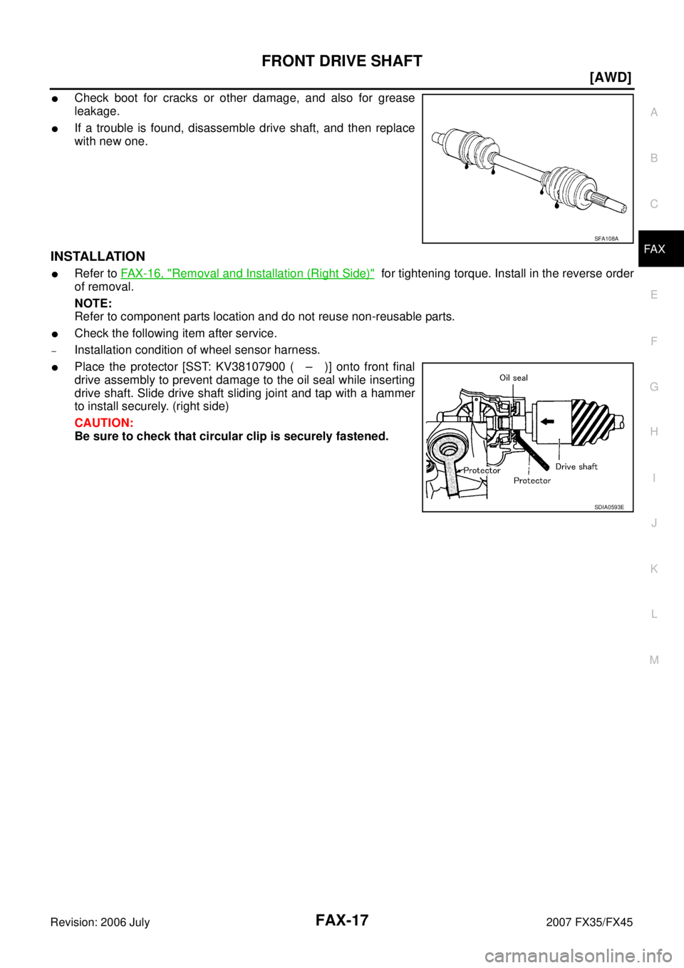
�Check boot for cracks or other damage, and also for grease
leakage.
�If a trouble is found, disassemble drive shaft, and then replace
with new one.
INSTALLATION
�Refer to FAX-16, "Removal and Installation (Right Side)" for tightening torque. Install in the reverse order
of removal.
NOTE:
Refer to component parts location and do not reuse non-reusable parts.
�Check the following item after service.
–Installation condition of wheel sensor harness.
�Place the protector [SST: KV38107900 ( – )] onto front final
drive assembly to prevent damage to the oil seal while inserting
drive shaft. Slide drive shaft sliding joint and tap with a hammer
to install securely. (right side)
CAUTION:
Be sure to check that circular clip is securely fastened.
SFA108A
SDIA0593E
![INFINITI FX35 2007 Service Manual FAX-2
[2WD]
PREPARATION
Revision: 2006 July 2007 FX35/FX45
[2WD]PREPARATIONPFP:00002
Special Service Tools NDS000BU
The actual shapes of Kent-Moore tools may differ from those of special service tools](/manual-img/42/57018/w960_57018-3087.png "INFINITI FX35 2007 Service Manual FAX-2
[2WD]
PREPARATION
Revision: 2006 July 2007 FX35/FX45
[2WD]PREPARATIONPFP:00002
Special Service Tools NDS000BU
The actual shapes of Kent-Moore tools may differ from those of special service tools")
![INFINITI FX35 2007 Service Manual FAX-6
[2WD]
SERVICE DATA AND SPECIFICATIONS (SDS)
Revision: 2006 July 2007 FX35/FX45
SERVICE DATA AND SPECIFICATIONS (SDS)PFP:00030
Wheel BearingNDS000BZ
Axial end play0.05 mm (0.002 in) or less](/manual-img/42/57018/w960_57018-3091.png "INFINITI FX35 2007 Service Manual FAX-6
[2WD]
SERVICE DATA AND SPECIFICATIONS (SDS)
Revision: 2006 July 2007 FX35/FX45
SERVICE DATA AND SPECIFICATIONS (SDS)PFP:00030
Wheel BearingNDS000BZ
Axial end play0.05 mm (0.002 in) or less")
![INFINITI FX35 2007 Service Manual PRECAUTIONS FAX-7
[AWD]
C E F
G H
I
J
K L
M A
B
FA X
Revision: 2006 July 2007 FX35/FX45
[AWD]PRECAUTIONSPFP:00001
CautionNDS000C0
Observe the following precautions when disassembling and s](/manual-img/42/57018/w960_57018-3092.png "INFINITI FX35 2007 Service Manual PRECAUTIONS FAX-7
[AWD]
C E F
G H
I
J
K L
M A
B
FA X
Revision: 2006 July 2007 FX35/FX45
[AWD]PRECAUTIONSPFP:00001
CautionNDS000C0
Observe the following precautions when disassembling and s")
![INFINITI FX35 2007 Service Manual FAX-8
[AWD]
PREPARATION
Revision: 2006 July 2007 FX35/FX45
PREPARATIONPFP:00002
Special Service Tools NDS000C1
The actual shapes of Kent-Moore tools may differ from those of special service tools illu](/manual-img/42/57018/w960_57018-3093.png "INFINITI FX35 2007 Service Manual FAX-8
[AWD]
PREPARATION
Revision: 2006 July 2007 FX35/FX45
PREPARATIONPFP:00002
Special Service Tools NDS000C1
The actual shapes of Kent-Moore tools may differ from those of special service tools illu")