DTC P0444, P0445 EVAP CANISTER PURGE VOLUME CONTROL SOLENOID VALVE
EC-1073
[VK45DE]
C
D E
F
G H
I
J
K L
M A
EC
Revision: 2006 July 2007 FX35/FX45
DTC P0444, P0445 EVAP CANISTER PURGE VOLUME CONTROL SOLENOID
VA LV E
PFP:14920
DescriptionNBS0047Y
SYSTEM DESCRIPTION
*1: ECM determines the start signal status by the signals of engine speed and battery voltage.
*2: This signal is sent to the ECM through CAN communication line.
This system controls flow rate of fuel vapor from the EVAP canister. The opening of the vapor by-pass pas-
sage in the EVAP canister purge volume control solenoid valve changes to control the flow rate. The EVAP
canister purge volume control solenoid valve repeats ON/OFF operation according to the signal sent from the
ECM. The opening of the valve varies for optimum engine control. The optimum value stored in the ECM is
determined by considering various engine conditions. When the engine is operating, the flow rate of fuel vapor
from the EVAP canister is regulated as the air flow changes.
COMPONENT DESCRIPTION
The EVAP canister purge volume control solenoid valve uses a ON/
OFF duty to control the flow rate of fuel vapor from the EVAP canis-
ter. The EVAP canister purge volume control solenoid valve is
moved by ON/OFF pulses from the ECM. The longer the ON pulse,
the greater the amount of fuel vapor that will flow through the valve.
CONSULT-II Reference Value in Data Monitor ModeNBS0047Z
Specification data are reference values.
Sensor Input signal to ECM ECM function Actuator
Crankshaft position sensor (POS)
Camshaft position sensor (PHASE) Engine speed*
1
EVAP canister
purge flow control EVAP canister purge vol-
ume control solenoid valve
Mass air flow sensor Amount of intake air
Engine coolant temperature sensor Engine coolant temperature
Battery Battery voltage*
1
Throttle position sensor Throttle position
Accelerator pedal position sensor Accelerator pedal position
A/F sensor 1 Density of oxygen in exhaust gas
(Mixture ratio feedback signal)
Fuel tank temperature sensor Fuel temperature in fuel tank
Wheel sensor Vehicle speed*
2
SEF337U
MONITOR ITEM CONDITION SPECIFICATION
PURG VOL C/V
�Engine: After warming up
�Selector lever: P or N
�Air conditioner switch: OFF
�No load Idle 0%
2,000 rpm —
VARIABLE INDUCTION AIR CONTROL SYSTEM (VIAS) EC-1355
[VK45DE]
C
D E
F
G H
I
J
K L
M A
EC
Revision: 2006 July 2007 FX35/FX45
VARIABLE INDUCTION AIR CONTROL SYSTEM (VIAS)PFP:14956
DescriptionNBS004GN
SYSTEM DESCRIPTION
*: The ECM determines the start signal status by the signals of engine speed and battery voltage.
When the engine is running at low or medium speed, the power valve is fully closed. Under this condition, the
effective suction port length is equivalent to the total length of the intake manifold collector's suction port
including the intake valve. This long suction port provides increased air intake which results in improved suc-
tion efficiency and higher torque generation.
The surge tank and one-way valve are provided. When engine is running at high speed, the ECM sends the
signal to the VIAS control solenoid valve. This signal introduces the intake manifold vacuum into the power
valve actuator and therefore opens the power valve to two suction passages together in the collector.
Under this condition, the effective port length is equivalent to the length of the suction port provided indepen-
dently for each cylinder. This shortened port length results in enhanced engine output with reduced suction
resistance under high speeds.
The power valve is always open regardless of the engine speed when gear position is in N or P.
Sensor Input signal to ECM ECM function Actuator
Crankshaft position sensor (POS)
Camshaft position sensor (PHASE) Engine speed*
VIAS control VIAS control solenoid valve
Mass air flow sensor Amount of intake air
Throttle position sensor Throttle position
Accelerator pedal position sensor Accelerator pedal position
Battery Battery voltage*
Engine coolant temperature sensor Engine coolant temperature
PBIB1876E
CYLINDER HEAD EM-233
[VK45DE]
C
D E
F
G H
I
J
K L
M A
EM
Revision: 2006 July 2007 FX35/FX45
�If the engine speed is out of specified range, check battery liquid for proper gravity. Check engine
speed again with normal battery gravity.
�If compression pressure is below minimum value, check valve clearances and parts associated with
combustion chamber (valve, valve seat, piston, piston ring, cylinder bore, cylinder head, cylinder head
gasket). After the checking, measure compression pressure again.
�If some cylinders have low compression pressure, pour small amount of engine oil into the spark plug
hole of the cylinder to re-check it for compression.
–If the added engine oil improves the compression, piston rings may be worn out or damaged. Check the
piston rings and replace if necessary.
–If the compression pressure remains at low level despite the addition of engine oil, valves may be mal-
functioning. Check valves for damage. Replace valve or valve seat accordingly.
�If two adjacent cylinders have respectively low compression pressure and their compression remains
low even after the addition of engine oil, cylinder head gaskets are leaking. In such a case, replace cyl-
inder head gaskets.
8. After inspection is completed, install removed parts in the reverse order of removal.
9. Start engine, and make sure that engine runs smoothly.
10. Perform trouble diagnosis. If DTC appears, erase it. Refer to EC-749, "
TROUBLE DIAGNOSIS" .
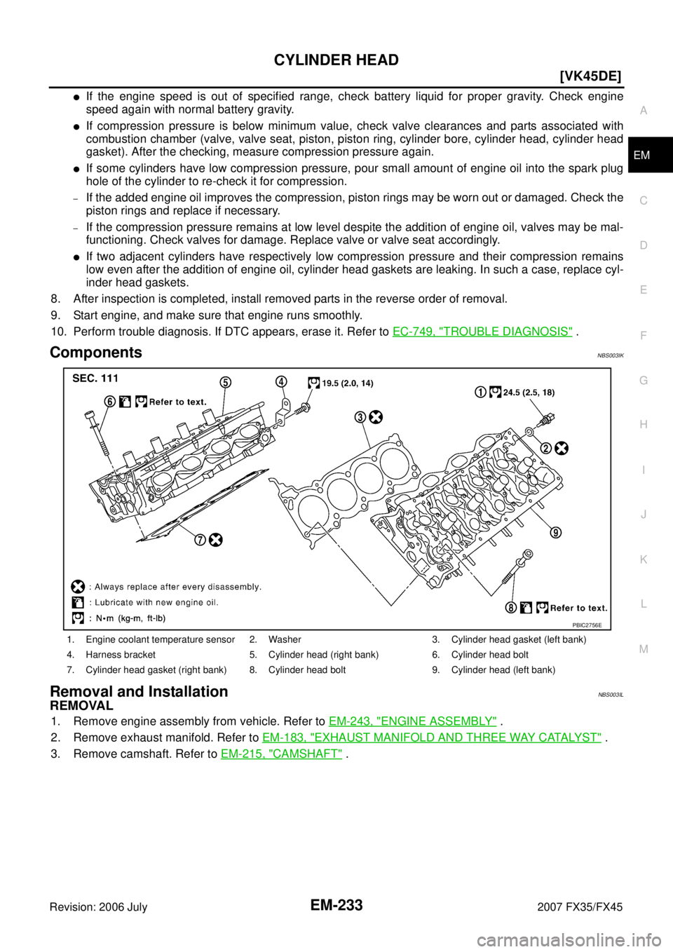
ComponentsNBS003IK
Removal and InstallationNBS003IL
REMOVAL
1. Remove engine assembly from vehicle. Refer to EM-243, "ENGINE ASSEMBLY" .
2. Remove exhaust manifold. Refer to EM-183, "
EXHAUST MANIFOLD AND THREE WAY CATALYST" .
3. Remove camshaft. Refer to EM-215, "
CAMSHAFT" .
1. Engine coolant temperature sensor 2. Washer 3. Cylinder head gasket (left bank)
4. Harness bracket 5. Cylinder head (right bank) 6. Cylinder head bolt
7. Cylinder head gasket (right bank) 8. Cylinder head bolt 9. Cylinder head (left bank)
PBIC2756E
![INFINITI FX35 2007 Service Manual DTC P0444, P0445 EVAP CANISTER PURGE VOLUME CONTROL SOLENOID VALVE
EC-1073
[VK45DE]
C
D E
F
G H
I
J
K L
M A
EC
Revision: 2006 July 2007 FX35/FX45
DTC P0444, P0445 EVAP CANISTER PURGE VO](/manual-img/42/57018/w960_57018-2448.png "INFINITI FX35 2007 Service Manual DTC P0444, P0445 EVAP CANISTER PURGE VOLUME CONTROL SOLENOID VALVE
EC-1073
[VK45DE]
C
D E
F
G H
I
J
K L
M A
EC
Revision: 2006 July 2007 FX35/FX45
DTC P0444, P0445 EVAP CANISTER PURGE VO")
![INFINITI FX35 2007 Service Manual VARIABLE INDUCTION AIR CONTROL SYSTEM (VIAS) EC-1355
[VK45DE]
C
D E
F
G H
I
J
K L
M A
EC
Revision: 2006 July 2007 FX35/FX45
VARIABLE INDUCTION AIR CONTROL SYSTEM (VIAS)PFP:14956
Descripti](/manual-img/42/57018/w960_57018-2730.png "INFINITI FX35 2007 Service Manual VARIABLE INDUCTION AIR CONTROL SYSTEM (VIAS) EC-1355
[VK45DE]
C
D E
F
G H
I
J
K L
M A
EC
Revision: 2006 July 2007 FX35/FX45
VARIABLE INDUCTION AIR CONTROL SYSTEM (VIAS)PFP:14956
Descripti")