Page 4325 of 4366

FRONT WIPER AND WASHER SYSTEM WW-19
C
D E
F
G H
I
J
L
M A
B
WW
Revision: 2006 July 2007 FX35/FX45
How to Proceed With Trouble DiagnosisNKS0032E
1. Confirm the symptoms and customer complaint.
2. Understand operation description and function description. Refer to WW-4, "
System Description" .
3. Perform the Preliminary Check. Refer to WW-19, "
Preliminary Check" .
4. Check symptom and repair or replace the cause of malfunction.
5. Does the front wiper and washer operate normally? If YES, GO TO 6. If NO, GO TO 4.
6. INSPECTION END
Preliminary CheckNKS0032F
CHECK POWER SUPPLY AND GROUND CIRCUIT
1. CHECK FUSE
Check for blown fuses.
Refer to WW-12, "
Wiring Diagram — WIPER —" .
OK or NG
OK >> GO TO 2
NG >> If fuse is blown, be sure to eliminate cause of malfunction before installing new fuse, Refer to PG-
3, "POWER SUPPLY ROUTING CIRCUIT" .
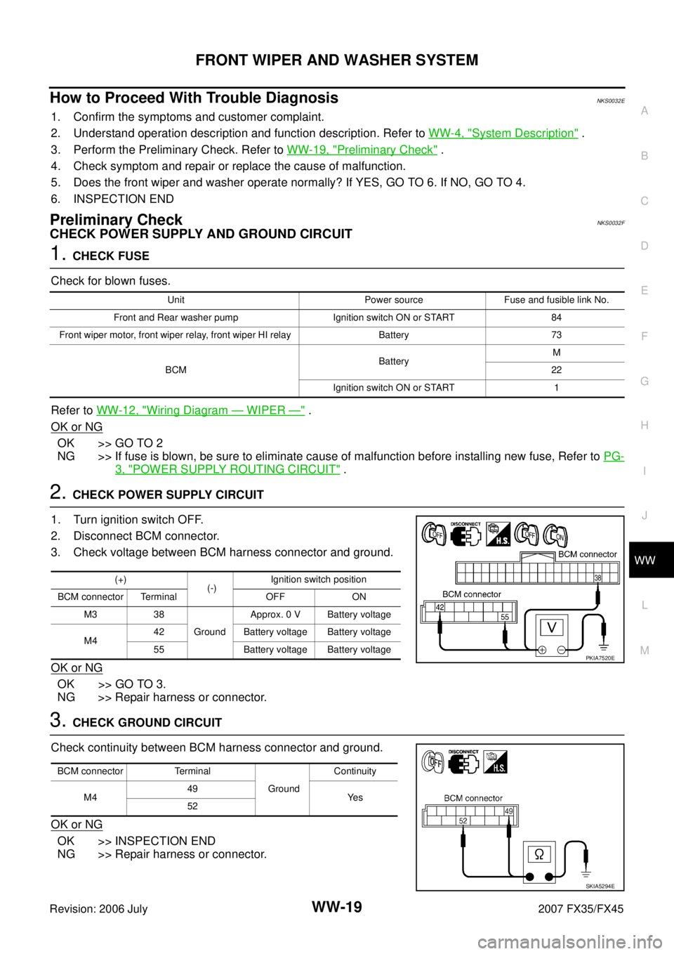
2. CHECK POWER SUPPLY CIRCUIT
1. Turn ignition switch OFF.
2. Disconnect BCM connector.
3. Check voltage between BCM harness connector and ground.
OK or NG
OK >> GO TO 3.
NG >> Repair harness or connector.
3. CHECK GROUND CIRCUIT
Check continuity between BCM harness connector and ground.
OK or NG
OK >> INSPECTION END
NG >> Repair harness or connector.
Unit Power source Fuse and fusible link No.
Front and Rear washer pump Ignition switch ON or START 84
Front wiper motor, front wiper relay, front wiper HI relay Battery 73
BCM Battery
M
22
Ignition switch ON or START 1
(+) (-) Ignition switch position
BCM connector Terminal OFF ON M3 38 Ground Approx. 0 V Battery voltage
M4 42 Battery voltage Battery voltage
55 Battery voltage Battery voltage
PKIA7520E
BCM connector Terminal Ground Continuity
M4 49
Ye s
52
SKIA5294E
Page 4345 of 4366

REAR WIPER AND WASHER SYSTEM WW-39
C
D E
F
G H
I
J
L
M A
B
WW
Revision: 2006 July 2007 FX35/FX45
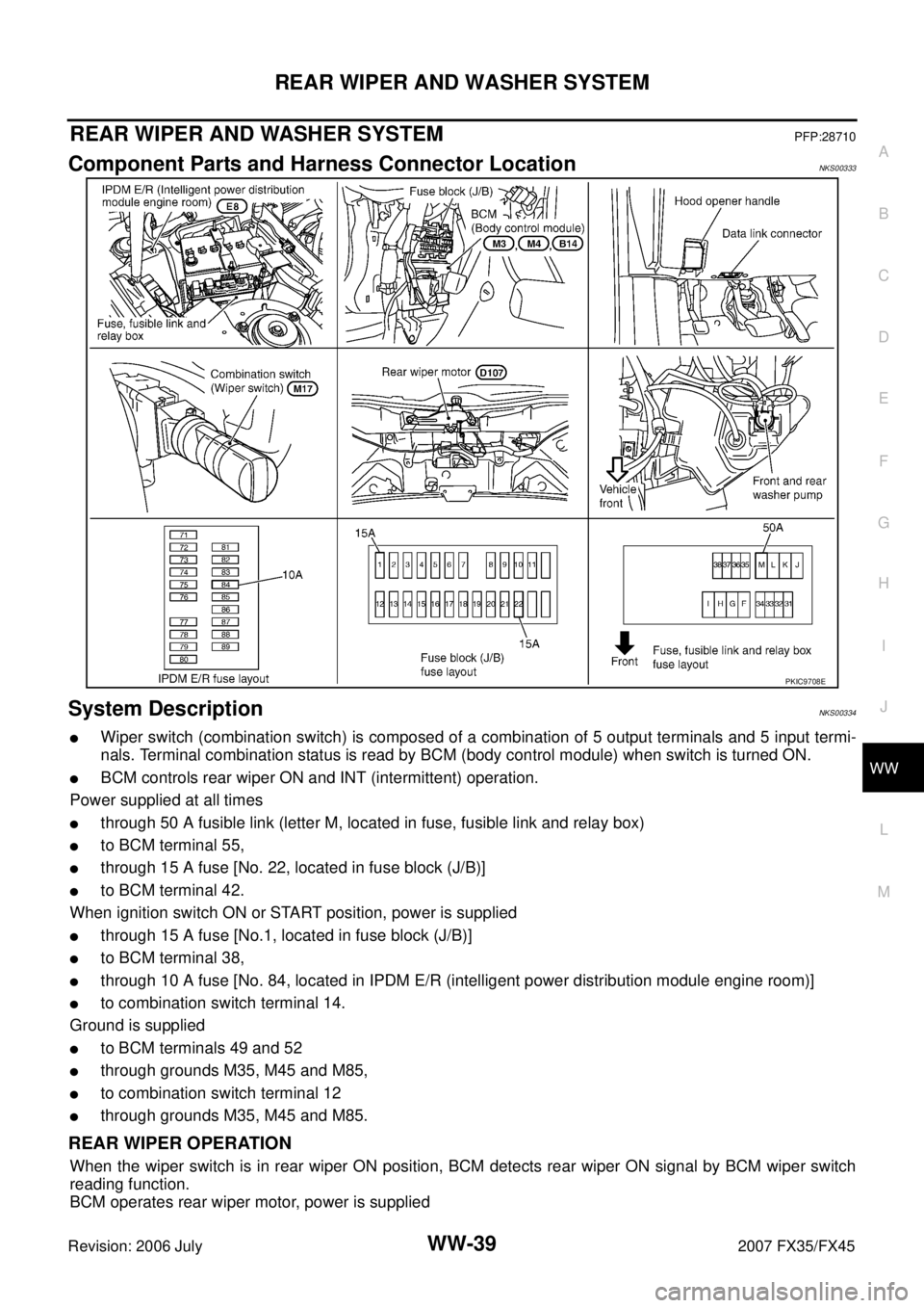
REAR WIPER AND WASHER SYSTEMPFP:28710
Component Parts and Harness Connector LocationNKS00333
System DescriptionNKS00334
�Wiper switch (combination switch) is composed of a combination of 5 output terminals and 5 input termi-
nals. Terminal combination status is read by BCM (body control module) when switch is turned ON.
�BCM controls rear wiper ON and INT (intermittent) operation.
Power supplied at all times
�through 50 A fusible link (letter M, located in fuse, fusible link and relay box)
�to BCM terminal 55,
�through 15 A fuse [No. 22, located in fuse block (J/B)]
�to BCM terminal 42.
When ignition switch ON or START position, power is supplied
�through 15 A fuse [No.1, located in fuse block (J/B)]
�to BCM terminal 38,
�through 10 A fuse [No. 84, located in IPDM E/R (intelligent power distribution module engine room)]
�to combination switch terminal 14.
Ground is supplied
�to BCM terminals 49 and 52
�through grounds M35, M45 and M85,
�to combination switch terminal 12
�through grounds M35, M45 and M85.
REAR WIPER OPERATION
When the wiper switch is in rear wiper ON position, BCM detects rear wiper ON signal by BCM wiper switch
reading function.
BCM operates rear wiper motor, power is supplied
PKIC9708E
Page 4351 of 4366

REAR WIPER AND WASHER SYSTEM WW-45
C
D E
F
G H
I
J
L
M A
B
WW
Revision: 2006 July 2007 FX35/FX45
How to Proceed With Trouble DiagnosisNKS00337
1. Confirm the symptoms and customer complaint.
2. Understand operation description and function description. Refer to WW-39, "
System Description" .
3. Perform the Preliminary Check. Refer to WW-45, "
Preliminary Check" .
4. Check symptom and repair or replace the cause of malfunction.
5. Does the rear wiper and washer operate normally? If YES, GO TO 6. If NO, GO TO 4.
6. INSPECTION END
Preliminary CheckNKS00338
CHECK POWER SUPPLY AND GROUND CIRCUIT
1. CHECK FUSES
Check for blown fuses.
Refer to WW-41, "Wiring Diagram — WIP/ R —" .
OK or NG
OK >> GO TO 2.
NG >> If fuse is blown, be sure to eliminate cause of malfunction before installing new fuse, Refer to PG-
3, "POWER SUPPLY ROUTING CIRCUIT" .
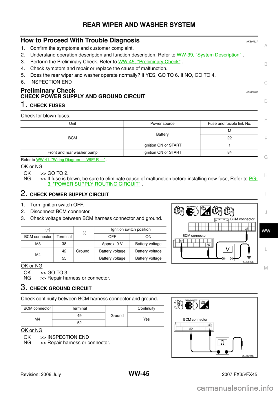
2. CHECK POWER SUPPLY CIRCUIT
1. Turn ignition switch OFF.
2. Disconnect BCM connector.
3. Check voltage between BCM harness connector and ground.
OK or NG
OK >> GO TO 3.
NG >> Repair harness or connector.
3. CHECK GROUND CIRCUIT
Check continuity between BCM harness connector and ground.
OK or NG
OK >> INSPECTION END
NG >> Repair harness or connector.
Unit Power source Fuse and fusible link No.
BCM Battery
M
22
Ignition ON or START 1
Front and rear washer pump Ignition ON or START 84
(+) (-) Ignition switch position
BCM connector Terminal OFF ON M3 38 Ground Approx. 0 V Battery voltage
M4 42 Battery voltage Battery voltage
55 Battery voltage Battery voltage
PKIA7520E
BCM connector Terminal Ground Continuity
M4 49
Ye s
52
SKIA5294E