Page 4313 of 4366
FRONT WIPER AND WASHER SYSTEM WW-7
C
D E
F
G H
I
J
L
M A
B
WW
Revision: 2006 July 2007 FX35/FX45
If switch is held in MIST position, low speed operation continues.
FAIL-SAFE FUNCTION
If an abnormality occurs in CAN communications, IPDM E/R holds the condition just before fail-safe status is
initiated until ignition switch is turned OFF. (If wipers were operating in LO just before the initiation of fail-safe
status, they continue to operate in LO until ignition switch is turned OFF.)
Page 4329 of 4366

FRONT WIPER AND WASHER SYSTEM WW-23
C
D E
F
G H
I
J
L
M A
B
WW
Revision: 2006 July 2007 FX35/FX45
Front Wiper Does Not OperateNKS0032I
CAUTION:
�During IPDM E/R fail-safe control, front wipers may not operate. Refer to PG-17, "CAN COMMUNI-
CATION LINE CONTROL" in “PG IPDM E/R” to make sure that it is not in fail-safe status.
1. ACTIVE TEST
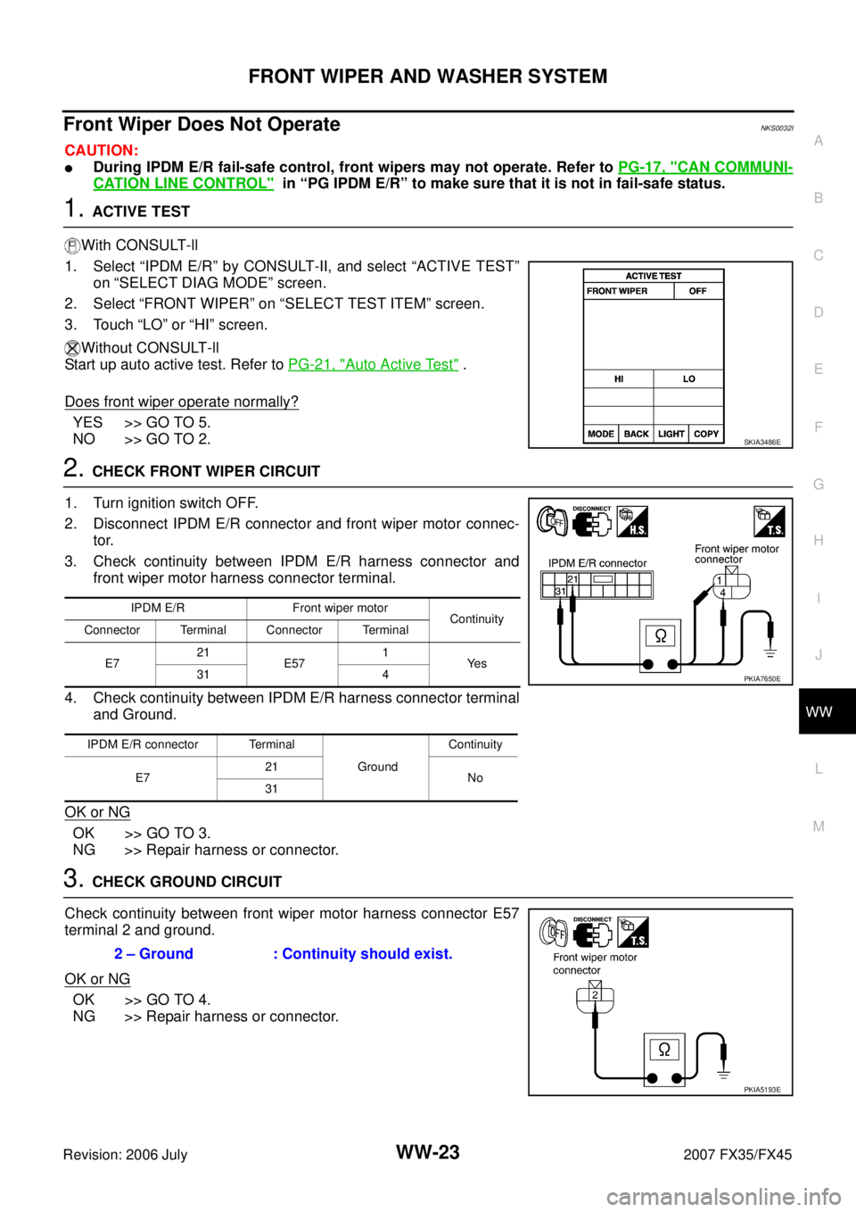
With CONSULT-ll
1. Select “IPDM E/R” by CONSULT-II, and select “ACTIVE TEST” on “SELECT DIAG MODE” screen.
2. Select “FRONT WIPER” on “SELECT TEST ITEM” screen.
3. Touch “LO” or “HI” screen.
Without CONSULT-ll
Start up auto active test. Refer to PG-21, "
Auto Active Test" .
Does front wiper operate normally?
YES >> GO TO 5.
NO >> GO TO 2.
2. CHECK FRONT WIPER CIRCUIT
1. Turn ignition switch OFF.
2. Disconnect IPDM E/R connector and front wiper motor connec- tor.
3. Check continuity between IPDM E/R harness connector and front wiper motor harness connector terminal.
4. Check continuity between IPDM E/R harness connector terminal and Ground.
OK or NG
OK >> GO TO 3.
NG >> Repair harness or connector.
3. CHECK GROUND CIRCUIT
Check continuity between front wiper motor harness connector E57
terminal 2 and ground.
OK or NG
OK >> GO TO 4.
NG >> Repair harness or connector.
SKIA3486E
IPDM E/R Front wiper motor Continuity
Connector Terminal Connector Terminal
E7 21
E57 1
Ye s
31 4
IPDM E/R connector Terminal Ground Continuity
E7 21
No
31
PKIA7650E
2 – Ground : Continuity should exist.
PKIA5193E
Page 4337 of 4366

FRONT WIPER AND WASHER SYSTEM WW-31
C
D E
F
G H
I
J
L
M A
B
WW
Revision: 2006 July 2007 FX35/FX45
After Front Wiper Operate for 10 Seconds, They Stop for 20 Seconds, and After
Repeating the Operations Five Times, They Become Inoperative
NKS0032Q
CAUTION:
�When auto-stop signal has not varied for 10 seconds or longer while IPDM E/R is operating front
wipers, IPDM E/R considers that front wipers are locked, and stops wiper output. That causes this
symptom.
�This status can be checked by “DATA MONITOR” of “IPDM E/R” on which “WIPER PROTECTION”
item shows “BLOCK”.
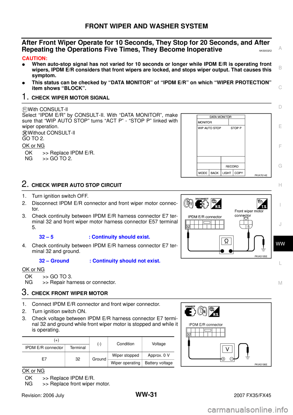
1. CHECK WIPER MOTOR SIGNAL
With CONSULT-ll
Select “IPDM E/R” by CONSULT-II. With “DATA MONITOR”, make
sure that “WIP AUTO STOP” turns “ACT P” - “STOP P” linked with
wiper operation.
Without CONSULT-ll
GO TO 2.
OK or NG
OK >> Replace IPDM E/R.
NG >> GO TO 2.
2. CHECK WIPER AUTO STOP CIRCUIT
1. Turn ignition switch OFF.
2. Disconnect IPDM E/R connector and front wiper motor connec- tor.
3. Check continuity between IPDM E/R harness connector E7 ter- minal 32 and front wiper motor harness connector E57 terminal
5.
4. Check continuity between IPDM E/R harness connector E7 ter- minal 32 and ground.
OK or NG
OK >> GO TO 3.
NG >> Repair harness or connector.
3. CHECK FRONT WIPER MOTOR
1. Connect IPDM E/R connector and front wiper connector.
2. Turn ignition switch ON.
3. Check voltage between IPDM E/R harness connector E7 termi- nal 32 and ground while front wiper motor is stopped and while it
is operating.
OK or NG
OK >> Replace IPDM E/R.
NG >> Replace front wiper motor.
PKIA7614E
32 – 5 : Continuity should exist.
32 – Ground : Continuity should not exist.
PKIA5195E
(+) (-) Condition Voltage
IPDM E/R connector Terminal
E7 32 Ground Wiper stopped Approx. 0 V
Wiper operating Battery voltage
PKIA5196E
Page 4356 of 4366

WW-50
REAR WIPER AND WASHER SYSTEM
Revision: 2006 July 2007 FX35/FX45
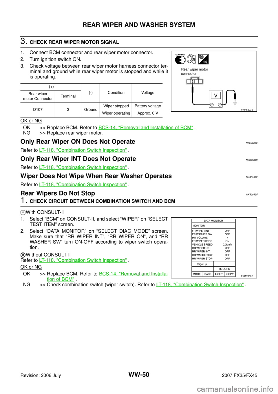
3. CHECK REAR WIPER MOTOR SIGNAL
1. Connect BCM connector and rear wiper motor connector.
2. Turn ignition switch ON.
3. Check voltage between rear wiper motor harness connector ter- minal and ground while rear wiper motor is stopped and while it
is operating.
OK or NG
OK >> Replace BCM. Refer to BCS-14, "Removal and Installation of BCM" .
NG >> Replace rear wiper motor.
Only Rear Wiper ON Does Not OperateNKS0033C
Refer to LT- 11 8 , "Combination Switch Inspection" .
Only Rear Wiper INT Does Not OperateNKS0033D
Refer to LT- 11 8 , "Combination Switch Inspection" .
Wiper Does Not Wipe When Rear Washer OperatesNKS0033E
Refer to LT- 11 8 , "Combination Switch Inspection" .
Rear Wipers Do Not StopNKS0033F
1. CHECK CIRCUIT BETWEEN COMBINATION SWITCH AND BCM
With CONSULT-ll
1. Select “BCM” on CONSULT-II, and select “WIPER” on “SELECT TEST ITEM” screen.
2. Select “DATA MONITOR” on “SELECT DIAG MODE” screen. Make sure that “RR WIPER INT”, “RR WIPER ON”, and “RR
WASHER SW” turn ON-OFF according to wiper switch opera-
tion.
Without CONSULT-ll
Refer to LT- 11 8 , "
Combination Switch Inspection" .
OK or NG
OK >> Replace BCM. Refer to BCS-14, "Removal and Installa-
tion of BCM" .
NG >> Check combination switch (wiper switch). Refer to LT- 11 8 , "
Combination Switch Inspection" .
(+)
(-) Condition Voltage
Rear wiper
motor Connector Te r m i n a l
D107 3 Ground Wiper stopped Battery voltage
Wiper operating Approx. 0 V
PKIA5203E
PKIA7660E