Page 4176 of 4366

SRS-30
TROUBLE DIAGNOSIS
Revision: 2006 July 2007 FX35/FX45
3. Touch “TROUBLE DIAG RECORD”.
NOTE:
With “TROUBLE DIAG RECORD”, diagnosis results previously
erased by a reset operation can be displayed.
4. Diagnostic code is displayed on “TROUBLE DIAG RECORD”.
5. Touch “PRINT”.
6. Compare diagnostic codes to SRS-30, "
DTC No. Index (“SELF-
DIAG [PAST]” or “TROUBLE DIAG RECORD”)" .
7. Touch “BACK” key of CONSULT-II until “SELECT SYSTEM” appears.
8. Turn ignition switch OFF, then turn off and disconnect CON- SULT-II, and both battery cables.
9. Repair the system as outlined by the “Repair order” in “Intermit- tent Malfunction Diagnostic Code Chart”, that corresponds to the
self-diagnostic result. For replacement procedure of component
parts, refer to the Removal and Installation procedure for the appropriate component.
10. Go to SRS-27, "
DIAGNOSTIC PROCEDURE 3" , for final inspection.
DTC No. Index (“SELF-DIAG [PAST]” or “TROUBLE DIAG RECORD”)
SRS697
SHIA0182E
Diagnostic item Explanation Repair order
“Recheck SRS at each replacement”
NO DTC IS
DETECTED. When malfunction is
indicated by the “AIR
BAG” warning lamp in
User mode.
�Low battery voltage (Less than 9V)�Go to SRS-27, "DIAGNOSTIC PRO-
CEDURE 3" .
�No malfunction is detected.�Go to SRS-27, "DIAGNOSTIC PRO-
CEDURE 3" .
DRIVER AIR BAG
MODULE
[OPEN]
[B1054]
�Driver air bag module circuit is open (including the spiral cable). 1. Visually check the wiring harness
connection.
2. Replace the harness if it has visible damage.
3. If the harness check result is OK, replace driver air bag module, diag-
nosis sensor unit and spiral cable.
DRIVER AIR BAG
MODULE
[VB-SHORT]
[B1055]
�Driver air bag module circuit is shorted to a power supply circuit
(including the spiral cable).
DRIVER AIR BAG
MODULE
[GND-SHORT]
[B1056]
�Driver air bag module circuit is shorted to ground (including the
spiral cable).
DRIVER AIR BAG
MODULE
[SHORT]
[B1057]
�Driver air bag module circuit is shorted between lines.
Page 4181 of 4366
TROUBLE DIAGNOSIS SRS-35
C
D E
F
G
I
J
K L
M A
B
SRS
Revision: 2006 July 2007 FX35/FX45
Trouble Diagnosis without CONSULT-IINHS0007I
DIAGNOSTIC PROCEDURE 6
Inspecting SRS Malfunctioning Parts by Using “AIR BAG” Warning Lamp — Diagnosis Mode
NOTE:
SRS will not enter Diagnosis mode if no malfunction is detected in User mode.
1. Turn ignition switch ON.
2. After “AIR BAG” warning lamp lights for 7 seconds, turn ignition switch OFF within 1 second.
3. Wait more than 3 seconds.
4. Repeat the steps 1 to 3 twice. (Perform three times in all.)
5. Turn ignition switch ON.
SRS is now in Diagnosis mode.
“AIR BAG” warning lamp operates in Diagnosis mode as follows:
WARNING LAMP FLASH CODE CHART
PHIA0532E
PHIA1233E
SHIA0028E
Page 4185 of 4366

TROUBLE DIAGNOSIS SRS-39
C
D E
F
G
I
J
K L
M A
B
SRS
Revision: 2006 July 2007 FX35/FX45
Trouble Diagnosis: “AIR BAG” Warning Lamp Does Not Turn OFFNHS0007J
DIAGNOSTIC PROCEDURE 7
1. CHECK THE DEPLOYMENT OF AIR BAG MODULE
Is air bag module deployed?
YES or NO
YES >> Refer to SRS-55, "COLLISION DIAGNOSIS" .
NO >> GO TO 2.
2. CHECK THE AIR BAG FUSE
Check 10A fuse [No. 13, located in fuse block (J/B)].
Refer to PG-3, "
POWER SUPPLY ROUTING CIRCUIT" .
OK or NG
OK >> GO TO 4.
NG >> GO TO 3.
3. CHECK AIR BAG FUSE AGAIN
Replace “AIR BAG” fuse and turn ignition switch ON.
Does the
“AIR BAG” fuse blow again?
YES >> Repair or replace main harness.
NO >> INSPECTION END
4. CHECK DIAGNOSIS SENSOR UNIT
Connect CONSULT-II and touch “START”.
Is “AIR BAG” displayed on CONSULT-II?
YES or NO
YES >> GO TO 5.
NO >> Visually check the wiring harness connection of diagno- sis sensor unit. If the harness connection check result is
OK, replace diagnosis sensor unit.
5. CHECK HARNESS CONNECTION
Is harness connection between warning lamp and diagnosis sensor unit OK?
OK or NG
OK >> Replace diagnosis sensor unit.
NG >> Connect “AIR BAG” warning lamp and diagnosis sensor unit connector properly. If “AIR BAG” warning lamp still does not go off, replace harness.
BCIA0030E
Page 4186 of 4366
SRS-40
TROUBLE DIAGNOSIS
Revision: 2006 July 2007 FX35/FX45
Trouble Diagnosis: “AIR BAG” Warning Lamp Does Not Turn ONNHS0007K
DIAGNOSTIC PROCEDURE 8
1. CHECK METER FUSE
Check 10A fuse [No. 14, located in fuse block (J/B)].
Refer to PG-3, "
POWER SUPPLY ROUTING CIRCUIT" .
OK or NG
OK >> GO TO 3.
NG >> GO TO 2.
2. CHECK METER FUSE AGAIN
Replace 10A fuse [No. 14, located in fuse block (J/B)] and turn ignition switch ON.
Does the meter fuse blow again?
YES >> Repair or replace the related harness.
NO >> INSPECTION END
3. CHECK HARNESS CONNECTION BETWEEN DIAGNOSIS SENSOR UNIT AND COMBINATION
METER
Disconnect diagnosis sensor unit connector and turn ignition switch ON.
Does “AIR BAG” warning lamp turn on?
YES or NO
YES >> Replace diagnosis sensor unit.
NO >> Replace combination meter assembly.
Page 4188 of 4366
SRS-42
DRIVER AIR BAG MODULE
Revision: 2006 July 2007 FX35/FX45
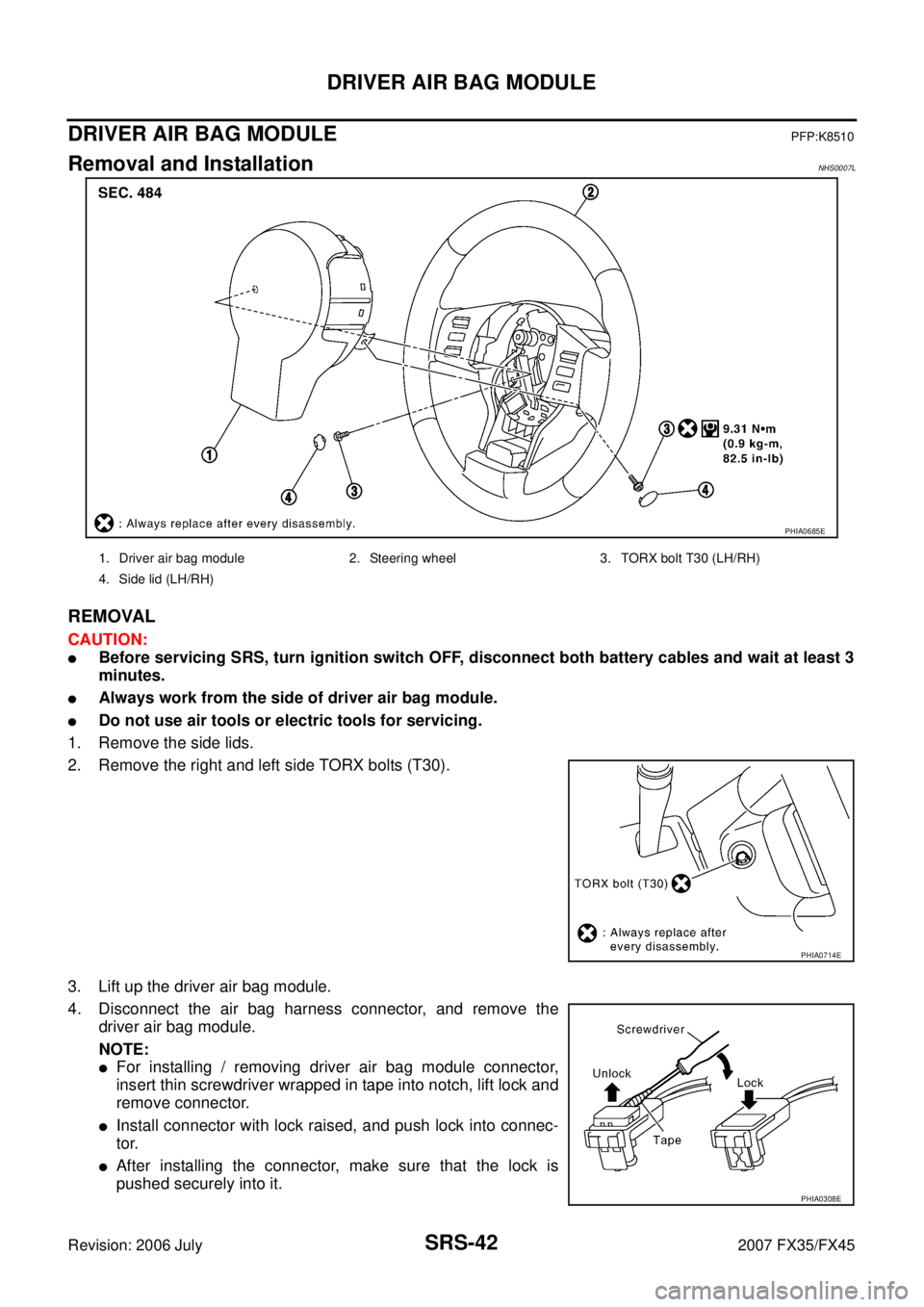
DRIVER AIR BAG MODULEPFP:K8510
Removal and InstallationNHS0007L
REMOVAL
CAUTION:
�Before servicing SRS, turn ignition switch OFF, disconnect both battery cables and wait at least 3
minutes.
�Always work from the side of driver air bag module.
�Do not use air tools or electric tools for servicing.
1. Remove the side lids.
2. Remove the right and left side TORX bolts (T30).
3. Lift up the driver air bag module.
4. Disconnect the air bag harness connector, and remove the driver air bag module.
NOTE:
�For installing / removing driver air bag module connector,
insert thin screwdriver wrapped in tape into notch, lift lock and
remove connector.
�Install connector with lock raised, and push lock into connec-
tor.
�After installing the connector, make sure that the lock is
pushed securely into it.
PHIA0685E
1. Driver air bag module 2. Steering wheel 3. TORX bolt T30 (LH/RH)
4. Side lid (LH/RH)
PHIA0714E
PHIA0308E
Page 4190 of 4366

SRS-44
SPIRAL CABLE
Revision: 2006 July 2007 FX35/FX45
SPIRAL CABLEPFP:25554
Removal and InstallationNHS0007M
REMOVAL
CAUTION:
�Before servicing SRS, turn ignition switch OFF, disconnect both battery cables and wait at least 3
minutes.
�Do not use air tools or electric tools for servicing.
1. Remove driver air bag module. Refer to SRS-42, "
Removal and Installation" .
2. Disconnect steering switch harness connector.
3. Set the steering wheel in the neutral position.
4. Removal steering wheel. Refer to PS-12, "
Removal and Installation" .
5. Remove steering column covers. Refer to IP-11, "
Removal and Installation" .
6. Loosen the spiral cable fixing screws, and then remove the spiral cable. CAUTION:
�Do not disassemble spiral cable.
�Do not apply lubricant to the spiral cable.
�Do not make an impact to the spiral cable by dropping etc. Replace the spiral cable if it has been
dropped or sustained an impact.
7. Disconnect the horn switch connector, and then the spiral cable connector.
CAUTION:
�Do not tap or bump the steering wheel.
�Also, with the steering linkage disconnected the cable
may snap by turning the steering wheel beyond the lim-
ited number of turns.
8. Remove the wiper washer switch and lighting switch from the spiral cable.
PHIA1336E
1. Steering wheel 2. Spiral cable 3. Driver air bag module connector
4. Screw 5. Wiper and washer switch 6. Lighting and turn signal switch
7. Steering column assembly 8. Steering column cover (upper) 9. Steering column cover (lower)
SHIA0193E
Page 4192 of 4366

SRS-46
FRONT PASSENGER AIR BAG MODULE
Revision: 2006 July 2007 FX35/FX45
FRONT PASSENGER AIR BAG MODULEPFP:K8515
Removal and InstallationNHS0007N
REMOVAL
CAUTION:
�Before servicing SRS, turn ignition switch OFF, disconnect both battery cables and wait at least 3
minutes.
�Always work from the side of or under front passenger air bag module.
�Do not use air tools or electric tools for servicing.
1. Disconnect front passenger air bag module connector (1).
2. Remove glove box assembly and instrument passenger lower panel. Refer to IP-11, "
Removal and Instal-
lation" .
3. Remove display control unit, if navigation system is equipped.
4. Remove tire pressure warning control unit, if tire pressure warning control system is equipped.
5. Remove the front passenger air bag module fixing bolt and nuts, and then remove front passenger air bag module.
CAUTION:
�Always place front passenger air bag module with caution
label side facing upward.
�Do not insert any foreign objects (screwdriver, etc.) into
front passenger air bag module.
�Do not disassemble front passenger air bag module.
�Do not use old bolts after removal; replace with new bolts.
PHIA1337E
PHIA0322E
PHIA0325E
Page 4194 of 4366

SRS-48
SIDE CURTAIN AIR BAG MODULE
Revision: 2006 July 2007 FX35/FX45
SIDE CURTAIN AIR BAG MODULEPFP:985P0
Removal and InstallationNHS0007O
REMOVAL
CAUTION:
�Before servicing SRS, turn ignition switch OFF, disconnect both battery cables and wait at least 3
minutes.
�Always work from the side of the side curtain air bag module.
�Do not use air tools or electric tools for servicing.
1. Remove headlining. Refer to EI-43, "
Removal and Installation" .
2. Disconnect side curtain air bag connector. NOTE:
�For installing / removing side curtain air bag module connec-
tor, insert thin screwdriver wrapped in tape into notch, lift lock
and remove connector.
�Install connector with lock raised, and push lock into connec-
tor.
�After installing the connector, make sure that the lock is
pushed securely into it.
3. Remove side curtain air bag module fixing bolts, and then remove the side curtain air bag module.
CAUTION:
�Always place the side curtain air bag module with the warn-
ing label facing upward.
�Do not disassemble side curtain air bag module.
�Do not insert any foreign objects (screwdriver, etc.) into air
bag module connector.
1. Side curtain air bag Inflator 2. Side curtain air bag 3. Bolt
4. Assist grip bracket 5. Bolt (There is no torque control)
PHIA0656E
PHIA0953J
PHIA0317E