Page 1233 of 4366
![INFINITI FX35 2007 Service Manual RADIATOR CO-43
[VK45DE]
C
D E
F
G H
I
J
K L
M A
CO
Revision: 2006 July 2007 FX35/FX45
11. Lift up and remove radiator.
CAUTION:
Do not damage or scratch A/C condenser and radiator core](/manual-img/42/57018/w960_57018-1232.png "INFINITI FX35 2007 Service Manual RADIATOR CO-43
[VK45DE]
C
D E
F
G H
I
J
K L
M A
CO
Revision: 2006 July 2007 FX35/FX45
11. Lift up and remove radiator.
CAUTION:
Do not damage or scratch A/C condenser and radiator core")
RADIATOR CO-43
[VK45DE]
C
D E
F
G H
I
J
K L
M A
CO
Revision: 2006 July 2007 FX35/FX45
11. Lift up and remove radiator.
CAUTION:
Do not damage or scratch A/C condenser and radiator core
when removing.
INSTALLATION
Install in the reverse order of removal.
INSPECTION AFTER INSTALLATION
�Check for leaks of engine coolant using radiator cap tester adapter [SST: EG17650301 (J33984-A)] and
radiator cap tester (commercial service tool). Refer to CO-38, "
LEAK CHECK" .
�Start and warm up engine. Visually Check if there is no leaks of engine coolant and A/T fluid.
Checking Radiator CapNBS003KL
�Check valve seat of radiator cap.
–Check if valve seat is swollen to the extent that the edge of the
plunger cannot be seen when watching it vertically from the top.
–Check if valve seat has no soil and damage.
�Pull negative-pressure valve to open it, and make sure that it
close completely when released.
–Make sure that there is no dirt or damage on the valve seat of
radiator cap negative-pressure valve.
–Make sure that there are no unusualness in the opening and
closing conditions of negative-pressure valve.
�Check radiator cap relief pressure.
–When connecting radiator cap to the radiator cap tester adapter
(SST) and the radiator cap tester (Commercial service tool),
apply engine coolant to the cap seal surface.
�Replace radiator cap if there is an unusualness.
PBIC1536E
PBIC2816E
SMA967B
Standard : 78 - 98 kPa (0.8 - 1.0 kg/cm2 , 11 - 14 psi)
Limit : 59 kPa (0.6 kg/cm
2 , 9 psi)
SLC755A
Page 1238 of 4366
![INFINITI FX35 2007 Service Manual CO-48
[VK45DE]
RADIATOR (ALUMINUM TYPE)
Revision: 2006 July 2007 FX35/FX45
4. Make sure that the rim is completely crimped down.
5. Make sure that there is no leakage. Refer to CO-48, "
INSPECTION"](/manual-img/42/57018/w960_57018-1237.png "INFINITI FX35 2007 Service Manual CO-48
[VK45DE]
RADIATOR (ALUMINUM TYPE)
Revision: 2006 July 2007 FX35/FX45
4. Make sure that the rim is completely crimped down.
5. Make sure that there is no leakage. Refer to CO-48, \"
INSPECTION\"")
CO-48
[VK45DE]
RADIATOR (ALUMINUM TYPE)
Revision: 2006 July 2007 FX35/FX45
4. Make sure that the rim is completely crimped down.
5. Make sure that there is no leakage. Refer to CO-48, "
INSPECTION" .
INSPECTION
1. Apply pressure with radiator cap tester adapter (SST) and radia-
tor cap tester (commercial service tool).
�provide used radiator and connect it to tested radiator using
radiator hoses as shown in the figure.
NOTE:
The used radiator should be tested beforehand to confirm it
has no leakage. If used one is not available, it is possible to
use new service part as a radiator testing tool.
WARNING:
To prevent the risk of hose coming undone while under pressure, securely fasten it down with
hose clamp.
CAUTION:
Attach hose to A/T fluid cooler to seal its inlet and outlet.
2. Check for leakage by soaking radiator in water container with the testing pressure applied. Standard height “H” : 8.0 - 8.4 mm (0.315 - 0.331 in)
SLC554A
Testing pressure
: 157 kPa (1.6 kg/cm
2 , 23 psi)PBIC1658E
PBIC1699E
Page 1241 of 4366
![INFINITI FX35 2007 Service Manual WATER PUMP CO-51
[VK45DE]
C
D E
F
G H
I
J
K L
M A
CO
Revision: 2006 July 2007 FX35/FX45
WAT E R P U MPPFP:21020
ComponentsNBS005S0
Removal and InstallationNBS003KR
CAUTION:
�When removin](/manual-img/42/57018/w960_57018-1240.png "INFINITI FX35 2007 Service Manual WATER PUMP CO-51
[VK45DE]
C
D E
F
G H
I
J
K L
M A
CO
Revision: 2006 July 2007 FX35/FX45
WAT E R P U MPPFP:21020
ComponentsNBS005S0
Removal and InstallationNBS003KR
CAUTION:
�When removin")
WATER PUMP CO-51
[VK45DE]
C
D E
F
G H
I
J
K L
M A
CO
Revision: 2006 July 2007 FX35/FX45
WAT E R P U MPPFP:21020
ComponentsNBS005S0
Removal and InstallationNBS003KR
CAUTION:
�When removing water pump, be careful not to get engine coolant on drive belts.
�Water pump can not be disassembled and should be replaced as a unit.
�After installing water pump, connect hose and clamp securely, then check for leaks using radiator
cap tester (commercial service tool) and radiator cap tester adapter [SST: EG17650301 (J33984-
A)].
REMOVAL
1. Drain engine coolant from drain plugs on radiator and both side of cylinder block. Refer to CO-38, "Chang-
ing Engine Coolant" and EM-249, "DISASSEMBLY" .
CAUTION:
�Perform this step when engine is cold.
�Do not spill engine coolant on drive belts.
2. Remove following parts:
�Engine front undercover
�Air duct (inlet); Refer to EM-177, "AIR CLEANER AND AIR DUCT" .
�Alternator, water pump and A/C compressor belt; Refer to EM-174, "DRIVE BELTS" .
3. Remove fan coupling with cooling fan, and then fan and water pump pulley.
4. Remove water pump.
�Engine coolant will leak from cylinder block, so have a receptacle ready under vehicle.
CAUTION:
�Handle the water pump vane so that it does not contact any other parts.
�Do not disassemble water pump.
1. Fan and water pump pulley 2. Water pump 3. Gasket
PBIC1538E
Page 1242 of 4366
CO-52
[VK45DE]
WATER PUMP
Revision: 2006 July 2007 FX35/FX45
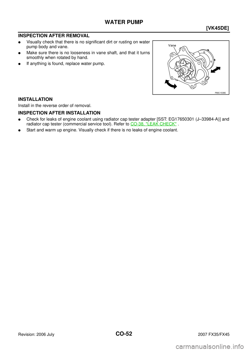
INSPECTION AFTER REMOVAL
�Visually check that there is no significant dirt or rusting on water
pump body and vane.
�Make sure there is no looseness in vane shaft, and that it turns
smoothly when rotated by hand.
�If anything is found, replace water pump.
INSTALLATION
Install in the reverse order of removal.
INSPECTION AFTER INSTALLATION
�Check for leaks of engine coolant using radiator cap tester adapter [SST: EG17650301 (J–33984-A)] and
radiator cap tester (commercial service tool). Refer to CO-38, "
LEAK CHECK" .
�Start and warm up engine. Visually check if there is no leaks of engine coolant.
PBIC1539E
Page 1245 of 4366
![INFINITI FX35 2007 Service Manual THERMOSTAT AND WATER CONTROL VALVE CO-55
[VK45DE]
C
D E
F
G H
I
J
K L
M A
CO
Revision: 2006 July 2007 FX35/FX45
Thermostat and Water Control Valve
�Install thermostat and water control va](/manual-img/42/57018/w960_57018-1244.png "INFINITI FX35 2007 Service Manual THERMOSTAT AND WATER CONTROL VALVE CO-55
[VK45DE]
C
D E
F
G H
I
J
K L
M A
CO
Revision: 2006 July 2007 FX35/FX45
Thermostat and Water Control Valve
�Install thermostat and water control va")
THERMOSTAT AND WATER CONTROL VALVE CO-55
[VK45DE]
C
D E
F
G H
I
J
K L
M A
CO
Revision: 2006 July 2007 FX35/FX45
Thermostat and Water Control Valve
�Install thermostat and water control valve with the whole circum-
ference of each flange part fit securely inside rubber ring. (The
example in the figure shows thermostat.)
�Install thermostat with jiggle valve facing upwards. (The position
deviation may be within the range of ±10 degrees)
�Install water control valve with the up-mark facing up and the
frame center part facing upwards. (The position deviation may
be within the range of ±10 degrees)
Water Outlet Pipe and Heater Pipe
First apply a neutral detergent to O-rings, then quickly insert the insertion parts of the water outlet pipe and
heater pipe into the installation holes.
INSPECTION AFTER INSTALLATION
�Check for leaks of engine coolant using radiator cap tester adapter [SST: EG17650301 (J33984-A)] and
radiator cap tester (commercial service tool). Refer to CO-38, "
LEAK CHECK" .
�Start and warm up engine. Visually check if there is no leaks of engine coolant.
PBIC0157E
PBIC0158E
Page 1246 of 4366
CO-56
[VK45DE]
SERVICE DATA AND SPECIFICATIONS (SDS)
Revision: 2006 July 2007 FX35/FX45
SERVICE DATA AND SPECIFICATIONS (SDS)PFP:00030
Standard and LimitNBS003KT
ENGINE COOLANT CAPACITY (APPROXIMATE)
Unit: (US qt, Imp qt)
RADIATOR
Unit: kPa (kg/cm2 , psi)
THERMOSTAT
WATER CONTROL VALVE
Engine coolant capacity [With reservoir tank at (“MAX” level)] 10.0 (10-5/8, 8-3/4)
Reservoir tank engine coolant capacity (at “MAX” level) 0.8 (7/8, 3/4)
Radiator cap relief pressure Standard 78 - 98 (0.8 - 1.0, 11 - 14)
Limit 59 (0.6, 9)
Leakage testing pressure 157 (1.6, 23)
Valve opening temperature 80 - 84 °C (176 - 183 °F)
Maximum valve lift More than 10 mm/ 95 °C (0.39 in/ 203 °F)
Valve closing temperature 77 °C (171 °F)
Valve opening temperature 93.5 - 96.5 °C (200 - 206 °F)
Maximum valve lift More than 8 mm/ 108 °C (0.315 in/ 226 °F)
Valve closing temperature 90 °C (194 °F)
Page 1250 of 4366
 “AIR BAG” and “SEAT
BELT PRE-TENSIONER”
NKS002ZB
The Supplemental")
DI-4
PRECAUTION
Revision: 2006 July 2007 FX35/FX45
PRECAUTION PFP:00011
Precautions for Supplemental Restraint System (SRS) “AIR BAG” and “SEAT
BELT PRE-TENSIONER”
NKS002ZB
The Supplemental Restraint System such as “AIR BAG” and “SEAT BELT PRE-TENSIONER”, used along
with a front seat belt, helps to reduce the risk or severity of injury to the driver and front passenger for certain
types of collision. This system includes seat belt switch inputs and dual stage front air bag modules. The SRS
system uses the seat belt switches to determine the front air bag deployment, and may only deploy one front
air bag, depending on the severity of a collision and whether the front occupants are belted or unbelted.
Information necessary to service the system safely is included in the SRS and SB section of this Service Man-
ual.
WARNING:
�To avoid rendering the SRS inoperative, which could increase the risk of personal injury or death
in the event of a collision which would result in air bag inflation, all maintenance must be per-
formed by an authorized NISSAN/INFINITI dealer.
�Improper maintenance, including incorrect removal and installation of the SRS, can lead to per-
sonal injury caused by unintentional activation of the system. For removal of Spiral Cable and Air
Bag Module, see the SRS section.
�Do not use electrical test equipment on any circuit related to the SRS unless instructed to in this
Service Manual. SRS wiring harnesses can be identified by yellow and/or orange harnesses or
harness connectors.
Page 1314 of 4366

Perform self-diagnosis of BCM. Refer to DI-66, \"
CONSULT-II Function (BCM)\" .
Self
-diagnosi")
DI-68
WARNING CHIME
Revision: 2006 July 2007 FX35/FX45
PRELIMINARY INSPECTION
1. CHECK BCM (CONSULT-II)
Perform self-diagnosis of BCM. Refer to DI-66, "
CONSULT-II Function (BCM)" .
Self
-diagnosis results
No malfunction detected >> GO TO 2.
Malfunction detected >> Check applicable parts, and repair or replace corresponding parts.
2. CHECK UNIFIED METER AND A/C AMP. (CONSULT-II)
Perform self-diagnosis of unified meter and A/C amp. Refer to DI-31, "
CONSULT-II Function (METER A/C
AMP)" .
Self
-diagnosis results
No malfunction detected >> INSPECTION END
Malfunction detected >> Check applicable parts, and repair or replace corresponding parts.
Symptom ChartNKS003I2
Power Supply and Ground Circuit InspectionNKS003I3
1. CHECK FUSE AND FUSIBLE LINK
Check for blown BCM fuses and fusible link.
OK or NG
OK >> GO TO 2.
NG >> Be sure to eliminate cause of malfunction before installing new fuse or fusible link. Refer to PG-3,
"POWER SUPPLY ROUTING CIRCUIT" .
Symptom Diagnoses/Service procedure
All warning chimes do not activate. Perform the following inspections.
1. DI-69, "
Combination Meter Buzzer Circuit Inspection".
2. DI-68, "
Power Supply and Ground Circuit Inspection".
Replace BCM, found normal function in the above inspections.
Ignition key
warning chime
does not acti-
vate. Without Intelligent Key.
Perform the following inspections.
1. DI-71, "
Front Door Switch (Driver Side) Signal Inspection".
2. DI-72, "
Key Switch Signal Inspection (Without Intelligent Key)".
Replace BCM, found normal function in the above inspections.
With Intelligent Key, when mechan-
ical key is used. Perform the following inspections.
1. DI-71, "
Front Door Switch (Driver Side) Signal Inspection".
2. DI-73, "
Key Switch and Ignition Knob Switch Signal Inspection (With Intelli-
gent Key, When Mechanical Key Is Used)".
Replace BCM, found normal function in the above inspections.
With Intelligent Key, when Intelli-
gent Key is carried with the driver. Refer to
BL-121, "
WARNING CHIME FUNCTION MALFUNCTION" .
Light warning chime does not activate. Perform the following inspections.
1. DI-71, "
Front Door Switch (Driver Side) Signal Inspection".
2. LT- 11 8 , "
Combination Switch Inspection".
Replace BCM, found normal function in the above inspections.
Seat belt warning chime does not activate. Perform
DI-75, "
Seat Belt Buckle Switch (Driver Side) Signal Inspection" .
Replace BCM, found normal function in the above inspection.
Power source Fuse and fusible link No.
Battery power supply M
22
Ignition power supply 1
![INFINITI FX35 2007 Service Manual CO-56
[VK45DE]
SERVICE DATA AND SPECIFICATIONS (SDS)
Revision: 2006 July 2007 FX35/FX45
SERVICE DATA AND SPECIFICATIONS (SDS)PFP:00030
Standard and LimitNBS003KT
ENGINE COOLANT CAPACITY (APPROXIMATE)](/manual-img/42/57018/w960_57018-1245.png "INFINITI FX35 2007 Service Manual CO-56
[VK45DE]
SERVICE DATA AND SPECIFICATIONS (SDS)
Revision: 2006 July 2007 FX35/FX45
SERVICE DATA AND SPECIFICATIONS (SDS)PFP:00030
Standard and LimitNBS003KT
ENGINE COOLANT CAPACITY (APPROXIMATE)")