Page 2886 of 4366
![INFINITI FX35 2007 Service Manual EM-94
[VQ35DE]
CAMSHAFT
Revision: 2006 July 2007 FX35/FX45
b. Use a feeler gauge, measure the clearance between valve lifter
and camshaft.
Valve clearance:
Unit: mm (in)
*: Approximately 80 °C (1](/manual-img/42/57018/w960_57018-2885.png "INFINITI FX35 2007 Service Manual EM-94
[VQ35DE]
CAMSHAFT
Revision: 2006 July 2007 FX35/FX45
b. Use a feeler gauge, measure the clearance between valve lifter
and camshaft.
Valve clearance:
Unit: mm (in)
*: Approximately 80 °C (1")
EM-94
[VQ35DE]
CAMSHAFT
Revision: 2006 July 2007 FX35/FX45
b. Use a feeler gauge, measure the clearance between valve lifter
and camshaft.
Valve clearance:
Unit: mm (in)
*: Approximately 80 °C (176 °F)
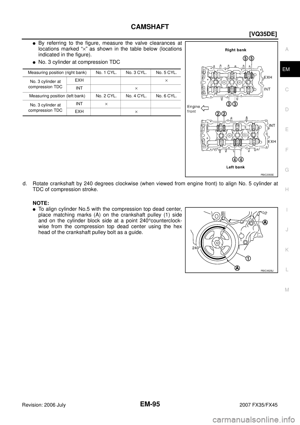
�By referring to the figure, measure the valve clearances at
locations marked “ ×” as shown in the table below (locations
indicated in the figure).
�No. 1 cylinder at compression TDC
c. Rotate crankshaft by 240 degrees clockwise (when viewed from engine front) to align No. 3 cylinder at TDC of its compression stroke.
NOTE:
�To align cylinder No.3 with the compression top dead center,
place matching marks (A) on the crankshaft pulley (1) side
and on the cylinder block side at a point 240 °counterclock-
wise from the compression top dead center using the hex
head of the crankshaft pulley bolt as a guide.
SEM139D
Items Cold Hot * (reference data)
Intake 0.26 - 0.34 (0.010 - 0.013) 0.304 - 0.416 (0.012 - 0.016)
Exhaust 0.29 - 0.37 (0.011 - 0.015) 0.308 - 0.432 (0.012 - 0.017)
Measuring position (right bank) No. 1 CYL. No. 3 CYL. No. 5 CYL.
No. 1 cylinder at
compression TDC EXH
×
INT ×
Measuring position (left bank) No. 2 CYL. No. 4 CYL. No. 6 CYL.
No. 1 cylinder at
compression TDC INT
×
EXH ×
PBIC2054E
PBIC4628J
Page 2887 of 4366
CAMSHAFT EM-95
[VQ35DE]
C
D E
F
G H
I
J
K L
M A
EM
Revision: 2006 July 2007 FX35/FX45
�By referring to the figure, measure the valve clearances at
locations marked “ ×” as shown in the table below (locations
indicated in the figure).
�No. 3 cylinder at compression TDC
d. Rotate crankshaft by 240 degrees clockwise (when viewed from engine front) to align No. 5 cylinder at TDC of compression stroke.
NOTE:
�To align cylinder No.5 with the compression top dead center,
place matching marks (A) on the crankshaft pulley (1) side
and on the cylinder block side at a point 240 °counterclock-
wise from the compression top dead center using the hex
head of the crankshaft pulley bolt as a guide.
Measuring position (right bank) No. 1 CYL. No. 3 CYL. No. 5 CYL.
No. 3 cylinder at
compression TDC EXH
×
INT ×
Measuring position (left bank) No. 2 CYL. No. 4 CYL. No. 6 CYL.
No. 3 cylinder at
compression TDC INT
×
EXH ×
PBIC2055E
PBIC4628J
Page 2889 of 4366
![INFINITI FX35 2007 Service Manual CAMSHAFT EM-97
[VQ35DE]
C
D E
F
G H
I
J
K L
M A
EM
Revision: 2006 July 2007 FX35/FX45
�Thickness of new valve lifter can be identified by stamp marks
on the reverse side (inside the cyli](/manual-img/42/57018/w960_57018-2888.png "INFINITI FX35 2007 Service Manual CAMSHAFT EM-97
[VQ35DE]
C
D E
F
G H
I
J
K L
M A
EM
Revision: 2006 July 2007 FX35/FX45
�Thickness of new valve lifter can be identified by stamp marks
on the reverse side (inside the cyli")
CAMSHAFT EM-97
[VQ35DE]
C
D E
F
G H
I
J
K L
M A
EM
Revision: 2006 July 2007 FX35/FX45
�Thickness of new valve lifter can be identified by stamp marks
on the reverse side (inside the cylinder).
Available thickness of valve lifter: 27 sizes with range 7.88 to 8.40 mm (0.3102 to 0.3307 in) in steps of 0.02
mm (0.0008 in) (when manufactured at factory). Refer to EM-154, "
Available Valve Lifter" .
CAUTION:
Install identification letter at the end, “U” and “R”, at each of proper positions. (Be careful of misinstal-
lation between intake and exhaust)
6. Install selected valve lifter.
7. Install camshaft. Refer to EM-88, "
INSTALLATION" .
8. Manually turn crankshaft pulley a few turns.
9. Make sure that the valve clearances for cold engine are within the specifications by referring to the speci- fied values. Refer to EM-93, "
INSPECTION" .
10. Install all removal parts in the reverse order of removal. Refer to EM-88, "
INSTALLATION" .
11. Warm up the engine, and check for unusual noise and vibration.
KBIA0119E
Stamp mark Thickness
INT EXH
788U
790U ·
·
840U 788R
790R ·
·
840R 7.88 mm
7.90 mm ·
·
8.40 mm
Page 2890 of 4366
![INFINITI FX35 2007 Service Manual EM-98
[VQ35DE]
OIL SEAL
Revision: 2006 July 2007 FX35/FX45
OIL SEALPFP:00100
Removal and Installation of Valve Oil SealNBS003GT
REMOVAL
1. Remove camshaft relating to valve oil seal to be removed. Ref](/manual-img/42/57018/w960_57018-2889.png "INFINITI FX35 2007 Service Manual EM-98
[VQ35DE]
OIL SEAL
Revision: 2006 July 2007 FX35/FX45
OIL SEALPFP:00100
Removal and Installation of Valve Oil SealNBS003GT
REMOVAL
1. Remove camshaft relating to valve oil seal to be removed. Ref")
EM-98
[VQ35DE]
OIL SEAL
Revision: 2006 July 2007 FX35/FX45
OIL SEALPFP:00100
Removal and Installation of Valve Oil SealNBS003GT
REMOVAL
1. Remove camshaft relating to valve oil seal to be removed. Refer to EM-83, "CAMSHAFT" .
2. Remove valve lifters. Refer to EM-83, "
CAMSHAFT" .
3. Turn crankshaft until the cylinder requiring new oil seals is at TDC. This will prevent valve from dropping into cylinder.
4. Remove valve collet.
�Compress valve spring with the valve spring compressor, the
attachment, the adapter (SST). Remove valve collet with a
magnet hand.
CAUTION:
When working, take care not to damage valve lifter holes.
5. Remove valve spring retainer, and valve spring.
6. Remove valve oil seal using the valve oil seal puller (SST).
INSTALLATION
1. Apply new engine oil on new valve oil seal joint and seal lip.
2. Using the valve oil seal drift (SST), press fit valve seal to height “H” shown in figure.
NOTE:
Dimension “H”: Height measured before valve spring seat instal-
lation
3. Install in the reverse order of removal after this step.
PBIC1803E
PBIC0884E
Intake and exhaust : 14.3 - 14.9 mm (0.563 - 0.587 in)
PBIC2769E
Page 2891 of 4366
![INFINITI FX35 2007 Service Manual OIL SEAL EM-99
[VQ35DE]
C
D E
F
G H
I
J
K L
M A
EM
Revision: 2006 July 2007 FX35/FX45
Removal and Installation of Front Oil SealNBS003GU
REMOVAL
1. Remove the following parts:
�Undercover](/manual-img/42/57018/w960_57018-2890.png "INFINITI FX35 2007 Service Manual OIL SEAL EM-99
[VQ35DE]
C
D E
F
G H
I
J
K L
M A
EM
Revision: 2006 July 2007 FX35/FX45
Removal and Installation of Front Oil SealNBS003GU
REMOVAL
1. Remove the following parts:
�Undercover")
OIL SEAL EM-99
[VQ35DE]
C
D E
F
G H
I
J
K L
M A
EM
Revision: 2006 July 2007 FX35/FX45
Removal and Installation of Front Oil SealNBS003GU
REMOVAL
1. Remove the following parts:
�Undercover
�Drive belts; Refer to EM-15, "DRIVE BELTS" .
�Crankshaft pulley; Refer to EM-64, "TIMING CHAIN" .
2. Remove front oil seal using a suitable tool. CAUTION:
Be careful not to damage front timing chain case and crank-
shaft.
INSTALLATION
1. Apply new engine oil to both oil seal lip and dust seal lip of new front oil seal.
2. Install front oil seal.
�Install front oil seal so that each seal lip is oriented as shown
in the figure.
�Using a suitable drift, press-fit until the height of front oil seal
is level with the mounting surface.
–Suitable drift: outer diameter 60 mm (2.36 in), inner diameter
50 mm (1.97 in).
�Make sure the garter spring is in position and seal lips not
inverted
CAUTION:
�Be careful not to damage front timing chain case and
crankshaft.
�Press-fit straight and avoid causing burrs or tilting oil
seal.
3. Install in the reverse order of removal after this step.
Removal and Installation of Rear Oil SealNBS003GV
REMOVAL
1. Remove oil pan (upper). Refer to EM-30, "OIL PAN AND OIL STRAINER" .
2. Remove transmission assembly. Refer to AT- 2 6 6 , "
TRANSMISSION ASSEMBLY" .
3. Remove drive plate. Refer to EM-123, "
CYLINDER BLOCK" .
SEM829E
SEM715A
SEM829E
Page 2892 of 4366
![INFINITI FX35 2007 Service Manual EM-100
[VQ35DE]
OIL SEAL
Revision: 2006 July 2007 FX35/FX45
4. Use a seal cutter (SST) to cut away liquid gasket and remove
rear oil seal retainer.
CAUTION:
Be careful not to damage mounting surfac](/manual-img/42/57018/w960_57018-2891.png "INFINITI FX35 2007 Service Manual EM-100
[VQ35DE]
OIL SEAL
Revision: 2006 July 2007 FX35/FX45
4. Use a seal cutter (SST) to cut away liquid gasket and remove
rear oil seal retainer.
CAUTION:
Be careful not to damage mounting surfac")
EM-100
[VQ35DE]
OIL SEAL
Revision: 2006 July 2007 FX35/FX45
4. Use a seal cutter (SST) to cut away liquid gasket and remove
rear oil seal retainer.
CAUTION:
Be careful not to damage mounting surface.
NOTE:
Regard both rear oil seal and retainer as an assembly.
INSTALLATION
1. Remove old liquid gasket on mating surfaces of cylinder block and oil pan (upper) using a scraper.
2. Apply new engine oil to both oil seal lip and dust seal lip of new rear oil seal retainer.
3. Apply a continuous bead of liquid gasket with the tube presser [SST: WS39930000 ( — )] to rear oil seal retainer as shown
in the figure.
Use Genuine RTV Silicone Sealant or equivalent. Refer to
GI-48, "
RECOMMENDED CHEMICAL PRODUCTS AND
SEALANTS" .
�Assembly should be done within 5 minutes after coating.
4. Install rear oil seal retainer to cylinder block. Refer to EM-123, "
CYLINDER BLOCK" .
�Make sure the garter spring is in position and seal lips not inverted.
5. Install in the reverse order of removal after this step.
SEM830E
PBIC2661E
Page 2893 of 4366
![INFINITI FX35 2007 Service Manual CYLINDER HEAD EM-101
[VQ35DE]
C
D E
F
G H
I
J
K L
M A
EM
Revision: 2006 July 2007 FX35/FX45
CYLINDER HEADPFP:11041
On-Vehicle ServiceNBS003GW
CHECKING COMPRESSION PRESSURE
1. Warm up engi](/manual-img/42/57018/w960_57018-2892.png "INFINITI FX35 2007 Service Manual CYLINDER HEAD EM-101
[VQ35DE]
C
D E
F
G H
I
J
K L
M A
EM
Revision: 2006 July 2007 FX35/FX45
CYLINDER HEADPFP:11041
On-Vehicle ServiceNBS003GW
CHECKING COMPRESSION PRESSURE
1. Warm up engi")
CYLINDER HEAD EM-101
[VQ35DE]
C
D E
F
G H
I
J
K L
M A
EM
Revision: 2006 July 2007 FX35/FX45
CYLINDER HEADPFP:11041
On-Vehicle ServiceNBS003GW
CHECKING COMPRESSION PRESSURE
1. Warm up engine thoroughly. Then, stop it.
2. Release fuel pressure. Refer to EC-85, "
FUEL PRESSURE RELEASE" .
3. Disconnect fuel pump fuse to avoid fuel injection during mea- surement.
4. Remove engine cover with power tool. Refer to EM-19, "
INTAKE MANIFOLD COLLECTOR" .
5. Remove ignition coil and spark plug from each cylinder. Refer to EM-42, "
IGNITION COIL" and EM-43,
"SPARK PLUG (PLATINUM-TIPPED TYPE)" .
6. Connect engine tachometer (not required in use of CONSULT-II).
7. Install compression gauge with an adapter (commercial service tool) onto spark plug hole.
�Use the adapter whose picking up end inserted to spark plug
hole is smaller than 20 mm (0.79 in) in diameter. Otherwise, it
may be caught by cylinder head during removal.
8. Turn ignition switch to “START” for cranking. When the gauge pointer stabilizes, read the compression pressure and the engine rpm. Perform these steps to check each cylinder.
Compression pressure:
Unit: kPa (kg/cm2 , psi) /rpm
CAUTION:
Always use a fully changed battery to obtain the specified engine speed.
�If the engine speed is out of the specified range, check battery liquid for proper gravity. Check the
engine speed again with normal battery gravity.
SBIA0466E
PBIC0900E
SBIA0533E
Standard Minimum Deference limit between cylinders
1,275 (13.0, 185) / 300 981 (10.0, 142) / 300 98 (1.0, 14) / 300
Page 2894 of 4366
![INFINITI FX35 2007 Service Manual EM-102
[VQ35DE]
CYLINDER HEAD
Revision: 2006 July 2007 FX35/FX45
�If compression pressure is below minimum value, check valve clearances and parts associated with
combustion chamber (valve, valve sea](/manual-img/42/57018/w960_57018-2893.png "INFINITI FX35 2007 Service Manual EM-102
[VQ35DE]
CYLINDER HEAD
Revision: 2006 July 2007 FX35/FX45
�If compression pressure is below minimum value, check valve clearances and parts associated with
combustion chamber (valve, valve sea")
EM-102
[VQ35DE]
CYLINDER HEAD
Revision: 2006 July 2007 FX35/FX45
�If compression pressure is below minimum value, check valve clearances and parts associated with
combustion chamber (valve, valve seat, piston, piston ring, cylinder bore, cylinder head, cylinder head
gasket). After the checking, measure compression pressure again.
�If some cylinder has low compression pressure, pour small amount of engine oil into the spark plug hole
of the cylinder to re-check it for compression.
–If the added engine oil improves the compression, piston rings may be worn out or damaged. Check
piston rings and replace if necessary.
–If the compression pressure remains at low level despite the addition of engine oil, valves may be mal-
functioning. Check valves for damage. Replace valve or valve seat accordingly.
�If two adjacent cylinders have respectively low compression pressure and their compression remains
low even after the addition of engine oil, cylinder head gaskets are leaking. In such a case, replace cyl-
inder head gaskets.
9. After inspection is completed, install removed parts.
10. Start the engine, and make sure that the engine runs smoothly.
11. Perform trouble diagnosis. If DTC appears, erase it. Refer to EC-87, "
TROUBLE DIAGNOSIS" .
ComponentsNBS003GX
Removal and InstallationNBS003GY
REMOVAL
1. Remove camshaft. Refer to EM-83, "CAMSHAFT" .
NOTE:
It is also possible to perform the following steps 2 and 3 just before removing camshaft.
2. Temporarily fit front suspension member to support engine. Refer to FSU-17, "
FRONT SUSPENSION
MEMBER" .
1. Engine rear lower slinger 2. Cylinder head (left bank) 3. Cylinder head bolt
4. Cylinder head (right bank) 5. Cylinder head gasket (right bank) 6. Cylinder head gasket (left bank)
7. Oil level gauge guide
SBIA0581E