Page 4185 of 4366

TROUBLE DIAGNOSIS SRS-39
C
D E
F
G
I
J
K L
M A
B
SRS
Revision: 2006 July 2007 FX35/FX45
Trouble Diagnosis: “AIR BAG” Warning Lamp Does Not Turn OFFNHS0007J
DIAGNOSTIC PROCEDURE 7
1. CHECK THE DEPLOYMENT OF AIR BAG MODULE
Is air bag module deployed?
YES or NO
YES >> Refer to SRS-55, "COLLISION DIAGNOSIS" .
NO >> GO TO 2.
2. CHECK THE AIR BAG FUSE
Check 10A fuse [No. 13, located in fuse block (J/B)].
Refer to PG-3, "
POWER SUPPLY ROUTING CIRCUIT" .
OK or NG
OK >> GO TO 4.
NG >> GO TO 3.
3. CHECK AIR BAG FUSE AGAIN
Replace “AIR BAG” fuse and turn ignition switch ON.
Does the
“AIR BAG” fuse blow again?
YES >> Repair or replace main harness.
NO >> INSPECTION END
4. CHECK DIAGNOSIS SENSOR UNIT
Connect CONSULT-II and touch “START”.
Is “AIR BAG” displayed on CONSULT-II?
YES or NO
YES >> GO TO 5.
NO >> Visually check the wiring harness connection of diagno- sis sensor unit. If the harness connection check result is
OK, replace diagnosis sensor unit.
5. CHECK HARNESS CONNECTION
Is harness connection between warning lamp and diagnosis sensor unit OK?
OK or NG
OK >> Replace diagnosis sensor unit.
NG >> Connect “AIR BAG” warning lamp and diagnosis sensor unit connector properly. If “AIR BAG” warning lamp still does not go off, replace harness.
BCIA0030E
Page 4186 of 4366
SRS-40
TROUBLE DIAGNOSIS
Revision: 2006 July 2007 FX35/FX45
Trouble Diagnosis: “AIR BAG” Warning Lamp Does Not Turn ONNHS0007K
DIAGNOSTIC PROCEDURE 8
1. CHECK METER FUSE
Check 10A fuse [No. 14, located in fuse block (J/B)].
Refer to PG-3, "
POWER SUPPLY ROUTING CIRCUIT" .
OK or NG
OK >> GO TO 3.
NG >> GO TO 2.
2. CHECK METER FUSE AGAIN
Replace 10A fuse [No. 14, located in fuse block (J/B)] and turn ignition switch ON.
Does the meter fuse blow again?
YES >> Repair or replace the related harness.
NO >> INSPECTION END
3. CHECK HARNESS CONNECTION BETWEEN DIAGNOSIS SENSOR UNIT AND COMBINATION
METER
Disconnect diagnosis sensor unit connector and turn ignition switch ON.
Does “AIR BAG” warning lamp turn on?
YES or NO
YES >> Replace diagnosis sensor unit.
NO >> Replace combination meter assembly.
Page 4187 of 4366

TROUBLE DIAGNOSIS SRS-41
C
D E
F
G
I
J
K L
M A
B
SRS
Revision: 2006 July 2007 FX35/FX45
Trouble Diagnosis: Passenger Seatbelt Warning SystemNHS0009V
1. CHECK THE SYSTEM 1
Check seatbelt warning lamp function.
Seatbelt warning lamp turns ON in the following conditions.
�Driver seatbelt is fastened.
�Occupant is on passenger seat.
�Passenger seatbelt is not fasten.
OK or NG
OK >> GO TO 2.
NG >> Check the followings.
�Harness between air bag diagnosis sensor unit and combination meter.
�Seatbelt buckle switch (passenger side) circuit.
�Seatbelt buckle switch (passenger side).
If these are OK, replace air bag diagnosis sensor unit.
2. CHECK THE SYSTEM 2
Check seatbelt warning lamp function.
Seatbelt warning lamp turns OFF in the following conditions.
�Driver seatbelt is fastened.
�Occupant is on passenger seat.
�Passenger seatbelt is fastened.
OK or NG
OK >> System is OK.
NG >> Check the followings.
�Seatbelt buckle switch (passenger side) circuit.
�Seatbelt buckle switch (passenger side).
If these are OK, replace air bag diagnosis sensor unit.
Page 4189 of 4366

DRIVER AIR BAG MODULE SRS-43
C
D E
F
G
I
J
K L
M A
B
SRS
Revision: 2006 July 2007 FX35/FX45
CAUTION:
�Always place driver air bag module with pad side facing
upward.
�Do not insert any foreign objects (screwdriver, etc.) into
driver air bag module.
�Do not disassemble driver air bag module.
�Do not use old bolts after removal; replace with new bolts.
�Do not expose the driver air bag module to temperatures
exceeding 90 °C (194 °F).
�Replace driver air bag module if it has been dropped or sus-
tained an impact.
�Do not allow oil, grease or water to come in contact with the
driver air bag module.
INSTALLATION
Install in the reverse order of removal.
CAUTION:
�Fix the air bag module harness (shown as A in the figure) to
the harness fixing hook (shown as B in the figure).
�Be careful not to damage the harness while installing.
�Tighten the special bolts after exactly adjusting the centers of fixing holes on the air bag module
side and the steering wheel side. If the holes are misaligned, the bolt threads are damaged and the
module is not installed securely.
�After the work is completed, make sure no system malfunction is detected by air bag warning
lamp.
�In case that malfunction is detected by the air bag warning lamp, reset by the self-diagnosis func-
tion and delete the memory by CONSOULT–II.
�In case that malunction is still detected after the above operation, peform self-diagnosis to repair
malfunctions. Refer to Refer to SRS-20, "
SRS Operation Check" .
PHIA0320E
SBF814E
PHIA0885J
Page 4191 of 4366

SPIRAL CABLE SRS-45
C
D E
F
G
I
J
K L
M A
B
SRS
Revision: 2006 July 2007 FX35/FX45
INSTALLATION
Install in the reverse order of removal.
CAUTION:
�The spiral cable may snap by steering operation if the cable
is installed in an improper position.
�The neutral position is set as follows.
Turn quietly the spiral cable clockwise to the end position.
Then turn it counterclockwise (about 2 and half turns) and
stop turning at the point on which the stopper insertion
holes are in the same position.
The service part is installed in the neutral position by the
stopper and can be set without adjusting after the stopper
is removed.
�Do not turn the spiral cable rashly and also beyond the limit
number of turns. (These will cause cable snap.)
�Adjust the spiral cable locating pin (showed as A inthe fig-
ure) to the steering wheel locating pin hole (showed as C in
the figuer).
�Secure the air bag harness with the harness fixing hook.
�After the work is completed, make sure no system malfunc-
tion is detected by air bag warning lamp.
�In case that malfunction is detected by the air bag warning
lamp, reset by the self-diagnosis function and delete the
memory by CONSULT −II.
�In case that malfunction is still detected after the above
operation, perform self-diagnosis to repair malfunctions.
Refer to SRS-20, "
SRS Operation Check" .
PHIA0887J
Page 4193 of 4366

FRONT PASSENGER AIR BAG MODULE SRS-47
C
D E
F
G
I
J
K L
M A
B
SRS
Revision: 2006 July 2007 FX35/FX45
�Replace front passenger air bag module if it has been
dropped or sustained an impact.
�Do not expose the front passenger air bag module to tem-
peratures exceeding 90 °C (194 °F).
�Do not allow oil, grease or water to come in contact with the
front passenger air bag module.
�After front passenger air bag module inflates, the instru-
ment panel assembly should be replaced.
INSTALLATION
Install in the reverse order of removal.
CAUTION:
�Be careful not to damage the harness while installing.
�After the work is completed, make sure no system malfunction is detected by air bag warning
lamp.
�In case that malfunction is detected by the air bag warning lamp, reset by the self-diagnosis func-
tion and delete the memory by CONSULT −II.
�In case that malfunction is still detected after the above operation, perform self-diagnosis to repair
malfunctions. Refer to Refer to SRS-20, "
SRS Operation Check" .
SBF814E
Page 4195 of 4366
SIDE CURTAIN AIR BAG MODULE SRS-49
C
D E
F
G
I
J
K L
M A
B
SRS
Revision: 2006 July 2007 FX35/FX45
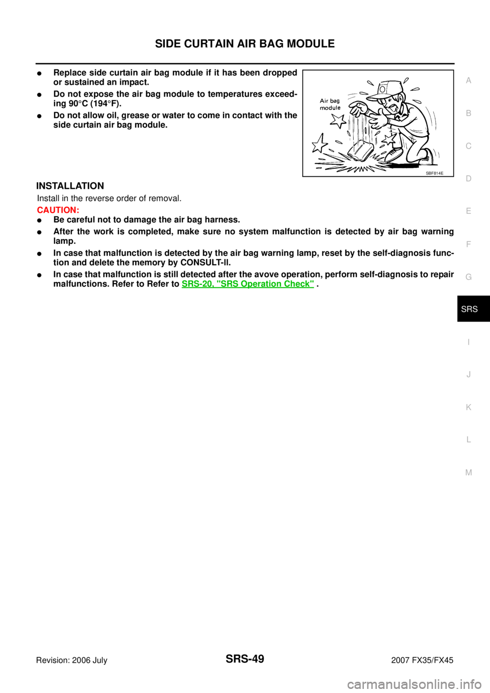
�Replace side curtain air bag module if it has been dropped
or sustained an impact.
�Do not expose the air bag module to temperatures exceed-
ing 90 °C (194 °F).
�Do not allow oil, grease or water to come in contact with the
side curtain air bag module.
INSTALLATION
Install in the reverse order of removal.
CAUTION:
�Be careful not to damage the air bag harness.
�After the work is completed, make sure no system malfunction is detected by air bag warning
lamp.
�In case that malfunction is detected by the air bag warning lamp, reset by the self-diagnosis func-
tion and delete the memory by CONSULT-ll.
�In case that malfunction is still detected after the avove operation, perform self-diagnosis to repair
malfunctions. Refer to Refer to SRS-20, "
SRS Operation Check" .
SBF814E
Page 4196 of 4366

SRS-50
CRASH ZONE SENSOR
Revision: 2006 July 2007 FX35/FX45
CRASH ZONE SENSORPFP:98531
Removal and InstallationNHS0007P
REMOVAL
CAUTION:
�Before servicing SRS, turn ignition switch OFF, disconnect both battery cables and wait at least 3
minutes.
�Do not use air tools or electric tools for servicing.
1. Remove front grille. Refer to EI-22, "
Removal and Installation" .
2. Remove crash zone sensor connector.
3. Remove crash zone sensor fixing nuts.
CAUTION:
�Replace crash zone sensor if it has been dropped or sustained an impact.
�Do not disassemble crash zone sensor.
�Do not use old fixing nuts after removal; replace with new nuts.
�Replace the crash zone sensor of deployed SRS driver air bag and deployed SRS front passenger
air bag.
INSTALLATION
Install in the reverse order of removal.
CAUTION:
�Be careful not to damage the crash zone sensor harness.
�After the work is completed, make sure no system malfunction is detected by air bag warning
lamp.
�In case that malfunction is detected by the air bag warning lamp, reset by the self-diagnosis func-
tion and delete the memory by CONSULT −ll.
�In case that malfunction is still detected after the above operation, perform self-diagnosis to repair
malfunctions. Refer to SRS-20, "
SRS Operation Check" .
PHIA0316E