Page 193 of 291

3
WHAT TO DO IN AN EMERGENCY
5SPARE TIRE
!
!!WARNING (Diesel only):
Never work on injection system with engine running or within 30 sec- onds after shutting off engine. High pressure pump, rail, injectors andhigh pressure pipes are subject to high pressure even after the engine stopped. The fuel jet produced byfuel leaks may cause serious in- jury, if it touch the body. People using pacemakers should not movethan 30cm closer to the ECU or wiring harness within the engine room while engine is running, sincethe high currents in the Common Rail system produce considerable magnetic fields. WARNING:
Do not remove the radiator cap whenthe engine is hot. This can allowcoolant to be blown out of the open- ing and cause serious burns.
5. If the water pump drive belt is bro- ken or coolant is leaking out, stop the engine immediately and call the nearest Hyundai dealer for assis- tance. 6. If you cannot find the cause of the
overheating, wait until the enginetemperature has returned to nor-mal. Then, if coolant has been lost, carefully add coolant to the reser- voir (Page 6-12) to bring the fluidlevel in the reservoir up to the half- way mark.
7. Proceed with caution, keeping alert for further signs of overheating. Ifoverheating happens again, call a Hyundai dealer for assistance.
CAUTION:
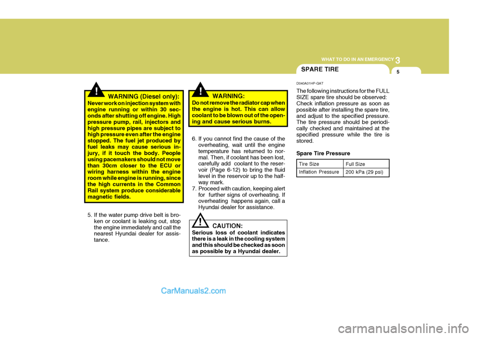
Serious loss of coolant indicates there is a leak in the cooling system and this should be checked as soonas possible by a Hyundai dealer. D040A01HP-GAT The following instructions for the FULL SIZE spare tire should be observed: Check inflation pressure as soon as possible after installing the spare tire,and adjust to the specified pressure. The tire pressure should be periodi- cally checked and maintained at thespecified pressure while the tire is stored. Spare Tire Pressure
Tire Size Inflation Pressure Full Size 200 kPa (29 psi)
Page 220 of 291

5
VEHICLE MAINTENANCE REQUIREMENTS
9EXPLANATION OF SCHEDULED MAINTENANCE ITEMS
!
F060M01A-AAT
o Engine Oil and Filter
The engine oil and filter should be changed at the intervals specified in the maintenance schedule. If the car is being driven in severe conditions,more frequent oil and filter changes are required. F060B01A-AAT
o Drive belts
Inspect all drive belts for evidence of cuts, cracks, excessive wear or oil saturation and replace if necessary. Drive belts should be checked periodi-cally for proper tension and adjusted as necessary. F060C01A-AAT
o Fuel filter
A clogged filter can limit the speed at
which the vehicle may be driven, dam-age the emission system and cause hard starting. If an excessive amountof foreign matter accumulates in the fuel tank, the filter may require re- placement more frequently. After installing a new filter, run the
engine for several minutes, and checkfor leaks at the connections. Fuel fil- ters should be installed by trained technicians. WARNING (Diesel only):
Never work on injection system with
engine running or within 30 sec- onds after shutting off engine. High pressure pump, rail, injectors andhigh pressure pipes are subjected to high pressure even after the en- gine has been switched off. The fueljet produced by fuel leaks may cause serious injury, if it contacts with the body. People using pacemakersshould not move closer than 30cm to the ECU or wiring harness within the engine room with the enginerunning, since the high currents in the Common Rail system produce considerable magnetic fields.
F060D01TB-GAT
o Fuel Lines, Fuel Hoses and
Connections
Check the fuel lines, fuel hoses and connections for leakage and damage. Have a trained technician replace any damaged or leaking parts immediately.
Page 242 of 291

6
DO-IT-YOURSELF MAINTENANCE
19
Fluid level should be within "HOT" range
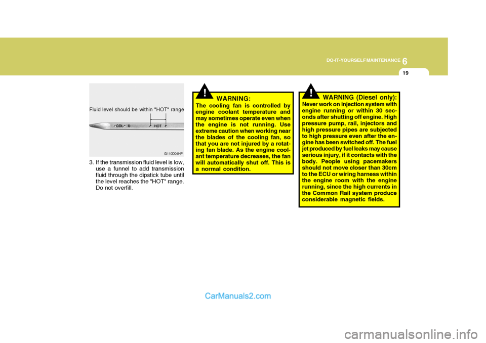
3. If the transmission fluid level is low, use a funnel to add transmission fluid through the dipstick tube until the level reaches the "HOT" range. Do not overfill. G110D04HP
!!WARNING:
The cooling fan is controlled by
engine coolant temperature and may sometimes operate even whenthe engine is not running. Use extreme caution when working near the blades of the cooling fan, sothat you are not injured by a rotat- ing fan blade. As the engine cool- ant temperature decreases, the fanwill automatically shut off. This is a normal condition. WARNING (Diesel only):
Never work on injection system with
engine running or within 30 sec- onds after shutting off engine. High pressure pump, rail, injectors and high pressure pipes are subjectedto high pressure even after the en- gine has been switched off. The fuel jet produced by fuel leaks may causeserious injury, if it contacts with the body. People using pacemakers should not move closer than 30cmto the ECU or wiring harness within the engine room with the engine running, since the high currents inthe Common Rail system produce considerable magnetic fields.
Page 259 of 291

6 DO-IT-YOURSELF MAINTENANCE
36
1. Keep all tires inflated to the correct
pressure.
2. Place the vehicle on level ground and press the front bumper & rear bumper down several times. Placevehicle at a distance of 3m (118.1 in.) from the test wall.
3. See that the vehicle is unloaded (except for full levels of coolant, engine oil and fuel, and spare tire,jack, and tools). Have the driver or equivalent weight placed in driver's seat.
4. Clean the headlight lens and turn on the headlight.
5. Open the hood.
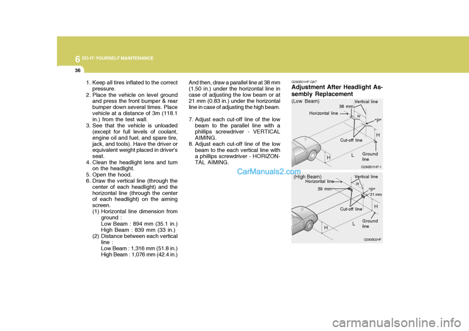
6. Draw the vertical line (through the center of each headlight) and thehorizontal line (through the center of each headlight) on the aiming screen.
(1) Horizontal line dimension from
ground : Low Beam : 894 mm (35.1 in.) High Beam : 839 mm (33 in.)
(2) Distance between each vertical line : Low Beam : 1,316 mm (51.8 in.) High Beam : 1,076 mm (42.4 in.) And then, draw a parallel line at 38 mm
(1.50 in.) under the horizontal line incase of adjusting the low beam or at 21 mm (0.83 in.) under the horizontal line in case of adjusting the high beam.
7. Adjust each cut-off line of the low beam to the parallel line with a phillips screwdriver - VERTICAL AIMING.
8. Adjust each cut-off line of the low beam to the each vertical line witha phillips screwdriver - HORIZON-TAL AIMING. G290B01HP-GAT
Adjustment After Headlight As- sembly Replacement
G290B02HP
LW
H Cut-off line
"P"
Vertical line
Horizontal line
Ground line
21 mm39 mm
(High Beam)
H
G290B01HP-1
LW
"P"
38 mm
H
H
(Low Beam)
Vertical line
Ground line
Cut-off line
Horizontal line
Page 280 of 291
9 VEHICLE SPECIFICATIONS
2
J010A02HP-GAT MEASUREMENT
4700 (4765* 1
)
1860
1795 (1840* 2
)
2750 15301530
Overall length Overall width Overall heightWheel base Wheel tread
Front
Rear
Type Wheel free play Oil pump type Ball and nut, torsion bar type (Integral type) 0 ~ 30 mm (0 ~ 1.18 in.)Vane type
J060A01Y-GAT FUEL SYSTEM
J020A01HP-GAT POWER STEERING J030A02HP-GAT TIRE
Standard Spare
J050A02HP-GAT BRAKE Dual hydraulic with brake booster Ventilated disc Disc type Disc type (with ABS)Drum type (without ABS) Cable operated on rear wheel
Type Front brake type Rear brake type Parking brake
ITEM Battery Alternator
J040A02HP-GAT ELECTRICAL
mm
Fuel tank capacity 75 liter
2.5 TCI
MF 90AH
90A (12 V)
Tire Size
255/65 R16 Full Size Kpa(psi)
2.9 CRDi
MF 100AH
110A (12V)GASOLINE
MF 68AH
120A (13.5V)DIESEL
E.C only Except E.C*1: With Bumper Guard *2: With Roof Rack Inflation Pressure
200kPa (29 psi)