2007 Hyundai Santa Fe ignition switch
[x] Cancel search: ignition switchPage 216 of 355
2
DRIVING YOUR HYUNDAI
5
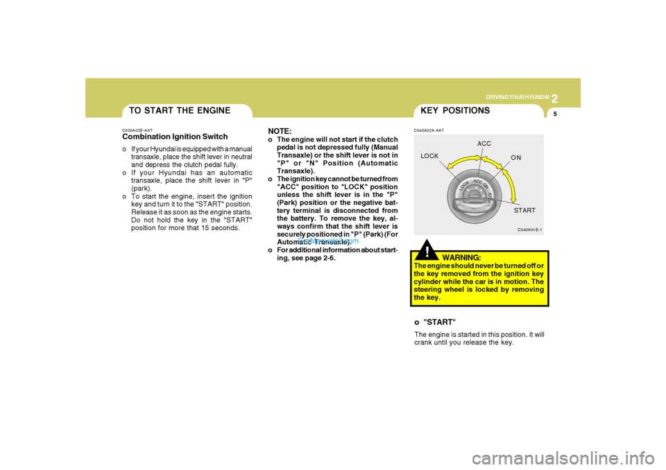
TO START THE ENGINEC030A02E-AATCombination Ignition Switcho If your Hyundai is equipped with a manual
transaxle, place the shift lever in neutral
and depress the clutch pedal fully.
o If your Hyundai has an automatic
transaxle, place the shift lever in "P"
(park).
o To start the engine, insert the ignition
key and turn it to the "START" position.
Release it as soon as the engine starts.
Do not hold the key in the "START"
position for more that 15 seconds.
NOTE:o The engine will not start if the clutch
pedal is not depressed fully (Manual
Transaxle) or the shift lever is not in
"P" or "N" Position (Automatic
Transaxle).
o The ignition key cannot be turned from
"ACC" position to "LOCK" position
unless the shift lever is in the "P"
(Park) position or the negative bat-
tery terminal is disconnected from
the battery. To remove the key, al-
ways confirm that the shift lever is
securely positioned in "P" (Park) (For
Automatic Transaxle).
o For additional information about start-
ing, see page 2-6.
!KEY POSITIONSC040A02A-AAT
WARNING:
The engine should never be turned off or
the key removed from the ignition key
cylinder while the car is in motion. The
steering wheel is locked by removing
the key.o "START"The engine is started in this position. It will
crank until you release the key.
C040A01E-1
LOCKACC
ON
START
Page 221 of 355
2
DRIVING YOUR HYUNDAI
10
CAUTION:
Never shift into "R" or "P" position while
the vehicle is moving.
!
The indicator lights in the instrument clus-
ter indicate the selector lever position when
the ignition is switched "ON". During sports
mode operation, the gear currently in use
displays in the numeral indicator.
AUTOMATIC TRANSAXLE
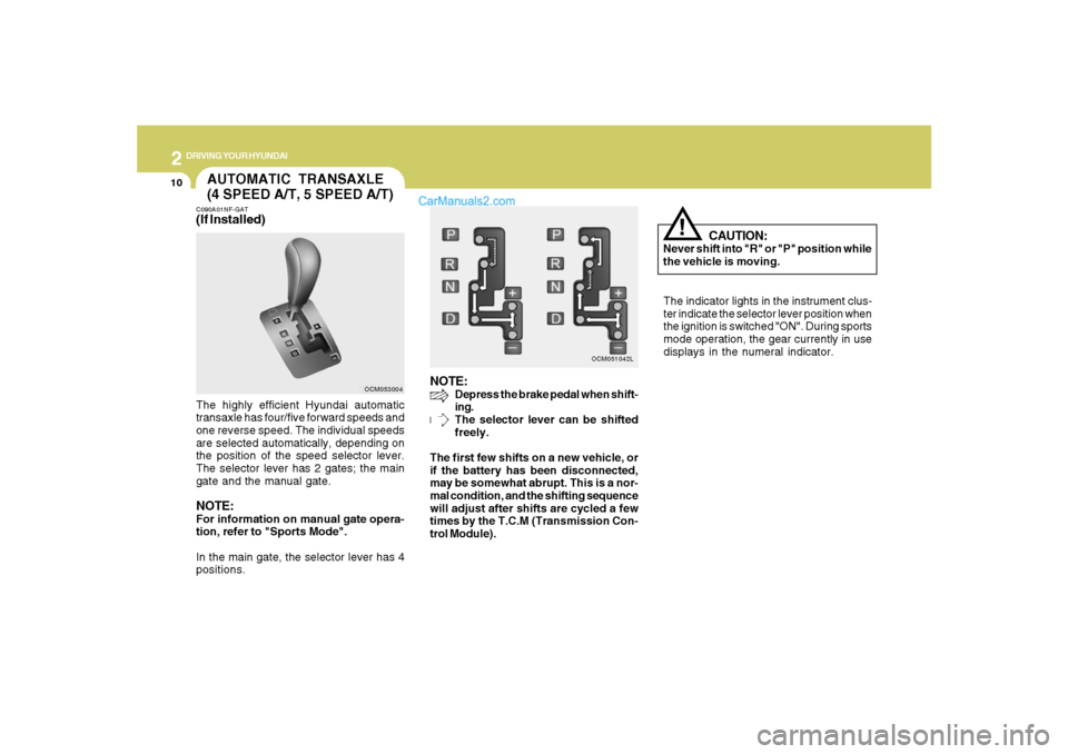
(4 SPEED A/T, 5 SPEED A/T)C090A01NF-GAT(If Installed)The highly efficient Hyundai automatic
transaxle has four/five forward speeds and
one reverse speed. The individual speeds
are selected automatically, depending on
the position of the speed selector lever.
The selector lever has 2 gates; the main
gate and the manual gate.NOTE:For information on manual gate opera-
tion, refer to "Sports Mode".
In the main gate, the selector lever has 4
positions.
NOTE:
Depress the brake pedal when shift-
ing.
The selector lever can be shifted
freely.
The first few shifts on a new vehicle, or
if the battery has been disconnected,
may be somewhat abrupt. This is a nor-
mal condition, and the shifting sequence
will adjust after shifts are cycled a few
times by the T.C.M (Transmission Con-
trol Module).
OCM053004OCM051042L
Page 230 of 355

2
DRIVING YOUR HYUNDAI
19
o In rare cases when it's unavoidable
that a AWD vehicle is to be inspected
on a 2WD roll tester, strictly follow the
procedures.
1. Check the tire pressures recom-
mended for your vehicle.
2. Place the front wheels on the roll
tester as shown in the illustration.
3. Release the parking brake.
4. Place the rear wheels on the tem-
porary free roller as shown in the
illustration.!
WARNING:
Keep away from the front of the vehicle
while inspecting.
OCM051013
Roll tester(Speedometer)Temporary free roller(9)For a speedometer test or inspection/
maintenance (I/M) program of a Santa
Fe AWD vehicle, use a four wheel chas-
sis dynamometer.
!
CAUTION:
Never engage the parking brake while
performing these tests. (8)The full-time AWD vehicle cannot be
towed by an ordinary tow truck. Make
sure that the vehicle is towed with all
four wheels raised off the ground.
o Roadside Assistance Program:
Off-roading is not covered. To re-
ceive service, the vehicle must be on
a publicly maintained road.
o If the vehicle is towed with only two
wheels raised off the ground, the
AWD system could be damaged.
o In unavoidable cases, if the vehicle
is being towed with all four wheels on
the ground, it should only be towed
forward.
o While towing, check the following
items.
1. The ignition switch is in "ACC" or
"ON".
2. Place the shift lever in neutral (For
Automatic Transaxle, "N" posi-
tion).
3. Release the parking brake.
NOTE:To avoid serious damage to your AWD
vehicle, limit towing to 10 mph and not for
more than 1 mile at ANY TIME.
Page 304 of 355
6
DO-IT-YOURSELF MAINTENANCE
18
!
CAUTION:
When replacing a fusible link, never use
anything but a new fusible link with the
same or lower amperage rating. Never
use a piece of wire or a higher-rated
fusible link. This could result in serious
damage and create a fire hazard.
G200B02HP-AATReplacing Accessory Fuses
OCM054002
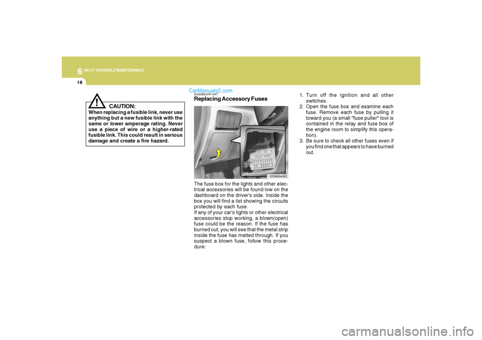
The fuse box for the lights and other elec-
trical accessories will be found low on the
dashboard on the driver's side. Inside the
box you will find a list showing the circuits
protected by each fuse.
If any of your car's lights or other electrical
accessories stop working, a blown(open)
fuse could be the reason. If the fuse has
burned out, you will see that the metal strip
inside the fuse has melted through. If you
suspect a blown fuse, follow this proce-
dure:1. Turn off the ignition and all other
switches.
2. Open the fuse box and examine each
fuse. Remove each fuse by pulling it
toward you (a small "fuse puller" tool is
contained in the relay and fuse box of
the engine room to simplify this opera-
tion).
3. Be sure to check all other fuses even if
you find one that appears to have burned
out.
Page 308 of 355
6
DO-IT-YOURSELF MAINTENANCE
22
If electrolyte gets on your skin,
thoroughly wash the contacted
area.
If you feel a pain or a burning
sensation, get medical atten-
tion immediately.
Wear eye protection when
charging or working near a bat-
tery.
Always provide ventilation
when working in an enclosed
space.
o When lifting a plastic-cased battery,
excessive pressure on the case may
cause battery acid to leak, resulting in
personal injury. Lift with a battery
carrier or with your hands on opposite
corners.
o Never attempt to charge the battery
when the battery cables are con-
nected.
o The electrical ignition system works
with high voltage.
Never touch these components with
the engine running or the ignition
switched on.
!
WARNING:
CHECKING ELECTRIC
COOLING FANS!
G220A01A-AAT
WARNING:
The cooling fan is controlled by engine
coolant temperature and may some-
times operate even when the engine is
not running. Use extreme caution when
working near the blades of the cooling
fan, so that you are not injured by a
rotating fan blade. As the engine coolant
temperature decreases the fan will au-
tomatically shut off. This is a normal
condition.
G220C01A-AATChecking Condenser Cooling FanThe condenser cooling fan should come
on automatically whenever the air condi-
tioning is in operation.G220B01A-AATChecking Engine Cooling FanThe engine cooling fan should come on
automatically if the engine coolant tem-
perature is high.
Page 319 of 355

6
DO-IT-YOURSELF MAINTENANCE
33
FUSE RATING
15A
15A
15A
10A
10A
25A
20A
10A
40A
40A
50A
20A
15A
10A
10A
10A
10A
10A
10A
10A
10A
15A
20A
25A
30ACIRCUIT PROTECTED
FUEL PUMP RELAY
H/LP LO LH RELAY
H/LP LO RH RELAY
FR FOG RELAY
I/P JUNCTION BOX
FR WIPER RELAY, RAIN SNSR RELAY, FRONT WIPER MOTOR, MULTIFUNCTION SWITCH
H/LP HI RELAY
HEAD LAMP, INSTRUMENT CLUSTER
IGNITION SWITCH
IGNITION SWITCH, START RELAY
I/P JUNCTION BOX
ATM RELAY(GASOLINE), AWD ECM
PCM(GASOLINE)
GENERATOR
VEHICLE SPEED SENSOR, PCM(GASOLINE), SEMI ACTIVE CONTROL MODULE(GASOLINE)
CON FAN #1 RELAY, CON FAN #2 RELAY
INPUT SPEED SENSOR, OUTPUT SPEED SENSOR, TRANSAXLE RANGE SWITCH, BACK-UP LAMP SWITCH
ABS CONTROL MODULE, ESC CONTROL MODULE, YAW RATE SENSOR, AWD ECM, STOP LAMP SWITCH(GASOLINE), MULTIPURPOSE
CHECK CONNECTOR
REAR COMBINATION LAMP LH, POSITION LAMP LH
REAR COMBINATION LAMP RH, POSITION LAMP RH
GLOVE BOX CAMP, ICM RELAY BOX
-
-
-
-
-
FUEL PUMP
H/LP LO LH
H/LP LO RH
FR FOG
H/LP
FR WIPER
H/LP HI
H/LP HI IND
IGN #1
IGN #2
BATT
AT M
TCU
ALT DSL
ECU
COOLING
B/UP UP
ESC
TAIL LH
TAIL RH
SPARE
SPARE
SPARE
SPARE
SPAREFUSE
Page 351 of 355
10
INDEX
4
Air intake control switch ............................................................1-126
Bi-level heating..........................................................................1-128
Defrosting / Defogging ..............................................................1-133
Fan speed control (Blower control)..........................................1-126
Temperature control.................................................................1-130
High-Mounted Rear Stop Light ......................................................1-112
Hood Release.................................................................................1-115
Horn..............................................................................................1-119
I
Ignition Switch ...................................................................................... 2-5
Instrument Cluster and Indicator Lights...........................................1-62
Instrument Panel Light Control (Rheostat).......................................1-84
Interior Light.......................................................................................1-93
J
Jump Starting...................................................................................... 3-3
K
Keys................................................................................................... 1-3
If you lose your keys ...................................................................3-21
Positions......................................................................................... 2-5
L
Light Bulbs Replacement ..................................................................6-24
Luggage Compartment ..................................................................1-109
Cargo security screen ..............................................................1-109
Luggage Net ..............................................................................1-110
Luggage under tray ...................................................................1-111M
Maintenance Intervals
Explanation of scheduled maintenance items ............................... 5-7
Maintenance under severe usage conditions............................... 5-6
Scheduled maintenance................................................................ 5-4
Service requirements.................................................................... 5-2
Mirrors
Automatic Dimming Rear View Mirror With Compass ................1-99
Day-night inside rearview mirror .................................................1-99
Homelink mirror.........................................................................1-102
Outside rearview mirror ...............................................................1-98
Outside rearview mirror Heater ..................................................1-98
O
Odometer / Trip Odometer ...............................................................1-72
Occupant Classification System ......................................................1-52
P
Parking Brake.................................................................................
1-108
Power Outlet......................................................................................1-86
Power Steering Fluid Level ...............................................................6-23
R
Rear Seat
Adjusting seatback angle .............................................................1-22
Folding rear seatback ..................................................................1-23
Rear Window Defroster Switch ........................................................1-88
Reporting Safety Defects .................................................................8-17
Risk of Rollover................................................................................... 2-3
Roof Rack......................................................................................1-111