2007 Hyundai Santa Fe maintenance schedule
[x] Cancel search: maintenance schedulePage 298 of 355
6
DO-IT-YOURSELF MAINTENANCE
12
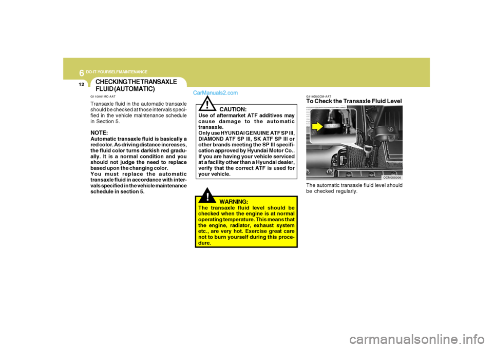
OCM055006 G110D02CM-AAT
To Check the Transaxle Fluid LevelThe automatic transaxle fluid level should
be checked regularly.
CHECKING THE TRANSAXLE
FLUID (AUTOMATIC)
!
WARNING:
The transaxle fluid level should be
checked when the engine is at normal
operating temperature. This means that
the engine, radiator, exhaust system
etc., are very hot. Exercise great care
not to burn yourself during this proce-
dure.
!
CAUTION:
Use of aftermarket ATF additives may
cause damage to the automatic
transaxle.
Only use HYUNDAI GENUINE ATF SP III,
DIAMOND ATF SP III, SK ATF SP III or
other brands meeting the SP III specifi-
cation approved by Hyundai Motor Co..
If you are having your vehicle serviced
at a facility other than a Hyundai dealer,
verify that the correct ATF is used for
your vehicle.
G110A01MC-AATTransaxle fluid in the automatic transaxle
should be checked at those intervals speci-
fied in the vehicle maintenance schedule
in Section 5.NOTE:Automatic transaxle fluid is basically a
red color. As driving distance increases,
the fluid color turns darkish red gradu-
ally. It is a normal condition and you
should not judge the need to replace
based upon the changing color.
You must replace the automatic
transaxle fluid in accordance with inter-
vals specified in the vehicle maintenance
schedule in section 5.
Page 300 of 355
6
DO-IT-YOURSELF MAINTENANCE
14
CHECKING THE BRAKES!
G120B01A-AATChecking the Brake Fluid Level
WARNING:Use caution when handling brake fluid. It
can damage your vision if it gets into
your eyes. It will also damage your
vehicle's paint if spilled on it and not
removed immediately.G120A01A-AAT
CAUTION:
Because brakes are essential to the
safe operation of the car, it is suggested
that they be checked and inspected by
your Hyundai dealer. The brakes should
be checked and inspected for wear at
those intervals specified in the vehicle
maintenance schedule in Section 5.
!
G120C02A-AATRecommended Brake FluidUse only hydraulic brake fluid conforming
to DOT 3 or DOT 4 specifications in your
braking system. Follow the instructions
printed on the container.
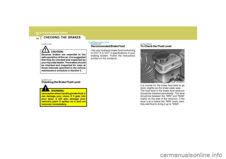
G120D01CM-AATTo Check the Fluid Level
OCM055014
It is normal for the brake fluid level to go
down slightly as the brake pads wear.
The fluid level in the brake fluid reservoir
should be checked periodically. The level
should be between the "MIN" and "MAX"
marks on the side of the reservoir. If the
level is at or below the "MIN" mark, care-
fully add fluid to bring it up to "MAX".
Page 309 of 355
6
DO-IT-YOURSELF MAINTENANCE
23
G240A01A-AATPower Steering HosesIt is suggested that you check the power
steering hose connections for fluid leak-
age at those intervals specified in the ve-
hicle maintenance schedule in Section 5.
The power steering hoses should be re-
placed if there is severe surface cracking,
pulling, scuffing or worn spots. Deteriora-
tion of the hose could cause premature
failure.NOTE:o Grinding noise from the power steer-
ing pump may be heard immediately
after the engine is started in extremely
cold conditions (below - 4°F). If the
noise stops during warm up, there is
no abnormal function in the system. It
is due to a power steering fluid char-
acteristic in extremely cold condi-
tions.
oDo not start the engine when the power
steering oil reservoir is empty.
POWER STEERING FLUID
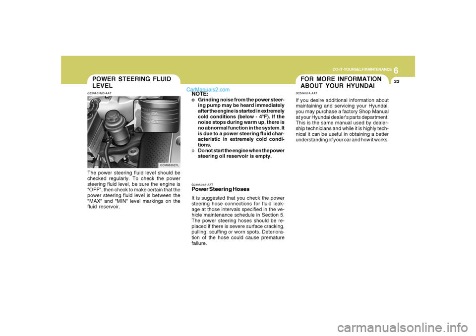
LEVELG230A01MC-AATThe power steering fluid level should be
checked regularly. To check the power
steering fluid level, be sure the engine is
"OFF", then check to make certain that the
power steering fluid level is between the
"MAX" and "MIN" level markings on the
fluid reservoir.
OCM055027L
FOR MORE INFORMATION
ABOUT YOUR HYUNDAIG250A01A-AATIf you desire additional information about
maintaining and servicing your Hyundai,
you may purchase a factory Shop Manual
at your Hyundai dealer's parts department.
This is the same manual used by dealer-
ship technicians and while it is highly tech-
nical it can be useful in obtaining a better
understanding of your car and how it works.
Page 323 of 355
7
EMISSION CONTROL SYSTEMS2
EMISSION CONTROL SYSTEM
H010B01A-AAT1. Crankcase Emission Control
SystemThe positive crankcase ventilation system
is employed to prevent air pollution caused
by blow-by gases being emitted from the
crankcase. This system supplies filtered
air to the crankcase through the air intake
hose. Inside the crankcase, the fresh air
mixes with blow-by gases, which then pass
through the PCV valve and into the induc-
tion system.
H010A01NF-AATYour Hyundai is equipped with an emis-
sion control system to meet all emission
regulations.
There are three emission control systems
which are as follows.
(1) Crankcase emission control system
(2) Evaporative emission control system
(3) Exhaust emission control system
In order to assure the proper function of the
emission control systems, it is recom-
mended that you have your car inspected
and maintained by an authorized Hyundai
dealer in accordance with the maintenance
schedule in this manual.
Caution for the Inspection and Mainte-
nance Test (With Electronic Stability
Control (ESC) system)
o To prevent the vehicle from misfiring
during dynamometer testing, turn the
Electronic Stability Control (ESC) sys-
tem off by pressing the ESC switch.
o After dynamometer testing is com-
pleted, turn the ESC system back on
by pressing the ESC switch again.
H010C01S-AAT2. Evaporative Emission Control (In-
cluding ORVR: Onboard Refuel-
ing Vapor Recovery) SystemThe Evaporative Emission Control Sys-
tem is designed to prevent fuel vapors from
escaping into the atmosphere.
(The ORVR system is designed to allow
the vapors from the fuel tank to be loaded
into a canister while refueling at the gas
station, preventing the escape of fuel va-
pors into the atmosphere.)CanisterFuel vapors generated inside the fuel tank
are absorbed and stored in the canister.
When the engine is running, the fuel va-
pors absorbed in the canister are drawn
into the induction system through the purge
control solenoid valve.
Cmhma-7.p653/17/2006, 10:29 AM 2
Page 351 of 355
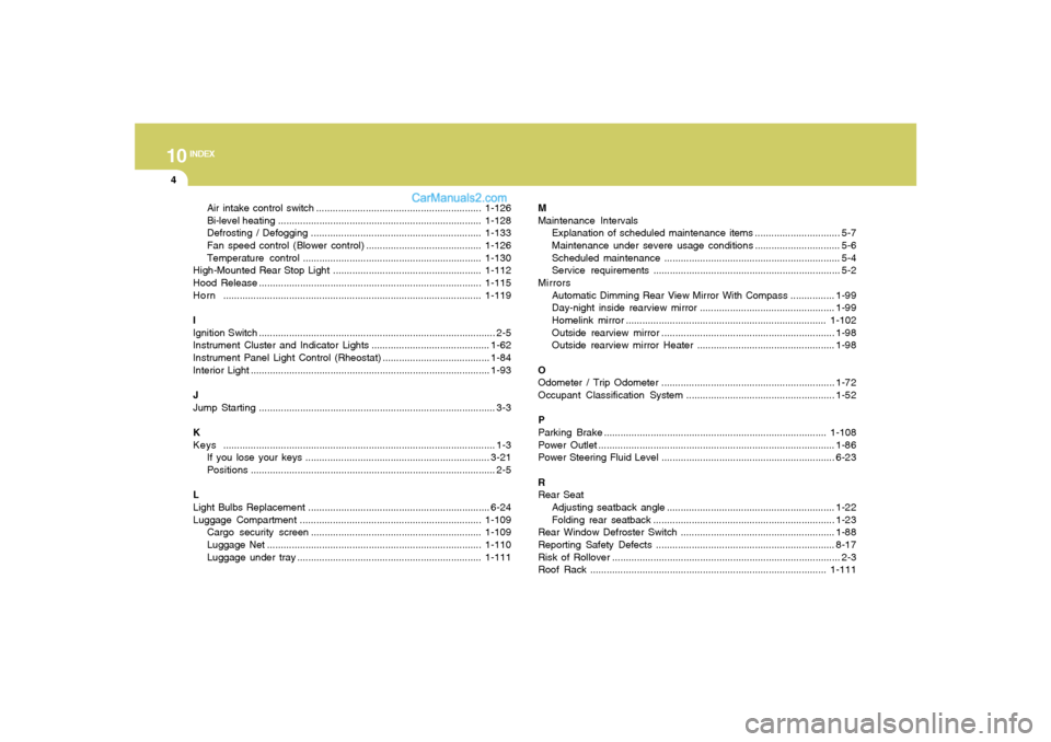
10
INDEX
4
Air intake control switch ............................................................1-126
Bi-level heating..........................................................................1-128
Defrosting / Defogging ..............................................................1-133
Fan speed control (Blower control)..........................................1-126
Temperature control.................................................................1-130
High-Mounted Rear Stop Light ......................................................1-112
Hood Release.................................................................................1-115
Horn..............................................................................................1-119
I
Ignition Switch ...................................................................................... 2-5
Instrument Cluster and Indicator Lights...........................................1-62
Instrument Panel Light Control (Rheostat).......................................1-84
Interior Light.......................................................................................1-93
J
Jump Starting...................................................................................... 3-3
K
Keys................................................................................................... 1-3
If you lose your keys ...................................................................3-21
Positions......................................................................................... 2-5
L
Light Bulbs Replacement ..................................................................6-24
Luggage Compartment ..................................................................1-109
Cargo security screen ..............................................................1-109
Luggage Net ..............................................................................1-110
Luggage under tray ...................................................................1-111M
Maintenance Intervals
Explanation of scheduled maintenance items ............................... 5-7
Maintenance under severe usage conditions............................... 5-6
Scheduled maintenance................................................................ 5-4
Service requirements.................................................................... 5-2
Mirrors
Automatic Dimming Rear View Mirror With Compass ................1-99
Day-night inside rearview mirror .................................................1-99
Homelink mirror.........................................................................1-102
Outside rearview mirror ...............................................................1-98
Outside rearview mirror Heater ..................................................1-98
O
Odometer / Trip Odometer ...............................................................1-72
Occupant Classification System ......................................................1-52
P
Parking Brake.................................................................................
1-108
Power Outlet......................................................................................1-86
Power Steering Fluid Level ...............................................................6-23
R
Rear Seat
Adjusting seatback angle .............................................................1-22
Folding rear seatback ..................................................................1-23
Rear Window Defroster Switch ........................................................1-88
Reporting Safety Defects .................................................................8-17
Risk of Rollover................................................................................... 2-3
Roof Rack......................................................................................1-111