2007 Hyundai H-1 (Grand Starex) clock
[x] Cancel search: clockPage 124 of 284

2
INSTRUMENTS AND CONTROLS
57
H260B03E-AAT
1. POWER ON-OFF Control Knob
The radio unit may be operated when the ignition key is in the "ACC" or "ON"position. Press the knob to switch the power on. The LCD shows the radio frequency in the radio mode or the CDtrack indicator in either the CD mode. To switch the power off, press the knob again. VOLUME Control Rotate the knob clockwise to increase the volume and turn the knob counter-clockwise to reduce the volume. BALANCE Control Pull and turn the control knob clock- wise to emphasize right speaker sound (left speaker sound will be attenuated).When the control knob is turned coun- terclockwise, left speaker sound will be emphasized (right speaker soundwill be attenuated). 2. FAD (Fader Control) Knob Turn the control knob counterclock- wise to emphasize front speaker sound(rear speaker sound will be attenu- ated). When the control knob is turned clockwise, rear speaker sound will beemphasized (front speaker sound will be attenuated).
3. BASS Control Knob Press to pop the knob out and turn to the left or right for the desired basstone. TREB (Treble Control) Knob Pull the bass control knob further out. Turn to the left or right for the desired treble tone.
4. SCAN Button When the scan button is pressed, the frequency will increase and the receiv-able stations will be tuned in one after another, receiving each station for 5 seconds. To stop scanning, press thescan button again.5. TUNE (Manual) Select Button Press the ( ) side or ( ) side to increase or to decrease the frequency.Press either button and hold down to continuously scroll. Release button once the desired station is reached. SEEK Operation (Automatic Channel Selection) Press the TUNE select button for 0.5 sec or more. Releasing it will automati-cally tune to the next available station with a beep sound. When the ( ) side is pressed longerthan 0.5 second, releasing will auto- matically tune to the next higher fre- quency and when the ( ) side ispressed longer than 0.5 second, re- leasing will automatically tune the next lower frequency. 6. BAND Selector Pressing the button changes the AM, FM1 and FM2 bands. The mode selected is displayed on LCD.
FM/AM
Page 130 of 284

2
INSTRUMENTS AND CONTROLS
63
BALANCE Control knob Pull the Bass control knob out further. Rotate the knob clockwise to empha-size right speaker sound (left speaker sound will be attenuated). When the control knob is turned counterclock-wise, left speaker sound will be em- phasized (right speaker sound will be attenuated).
3. TREBLE/FAD Control Knob TREBLE Control Knob
Press to pop the knob out and turn to the left or right for the desired trebletone. FAD (Fader Control) Knob Pull the Treble control knob out fur- ther. Turn the control knob counter- clockwise to emphasize front speakersound (rear speaker sound will be at- tenuated). When the control knob is turned clockwise, rear speaker soundwill be emphasized (front speaker sound will be attenuated).
H290B03E-GAT
1. POWER ON-OFF Control
Knob
The radio unit may be operated when the ignition key is in the "ACC" or "ON"position. Press the button to switch the power on. The display shows the radio frequency in the radio mode, the tapedirection indicator in the tape mode or CD track in either the CD mode. To switch the power off, press the buttonagain. VOLUME Control Rotate the knob clockwise to increase the volume and turn the knob counter- clockwise to reduce the volume.
2. BASS/BALANCE Control Knob
BASS Control Knob Press to pop the knob out. To increase the bass, rotate the knob clockwise,while to decrease the bass, rotate the knob counterclockwise. 4. TUNE (Manual) Select Button Press the ( ) side or ( ) side to increase or to decrease the frequency.Press either button and hold down to continuously scroll. Release button once the desired station is reached. SEEK Operation (Automatic Channel Selection) Press the TUNE select button for 0.5 sec or more. Releasing it will automati-cally tune to the next available station with a beep sound. When the ( ) side is pressed longerthan 0.5 second and releasing will automatically tune to the next higher frequency and when the ( ) side ispressed longer than 0.5 second, re- leasing will automatically tune to the next lower frequency.
5. PRESET Station Select But-
tons
Six (6) stations for AM, FM1 and FM2 respectively can be preset in the elec-tronic memory circuit.
Page 140 of 284
2
INSTRUMENTS AND CONTROLS
73ANTENNA
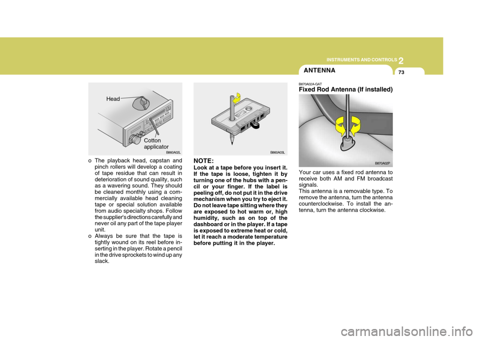
o The playback head, capstan and pinch rollers will develop a coating of tape residue that can result indeterioration of sound quality, such as a wavering sound. They should be cleaned monthly using a com-mercially available head cleaning tape or special solution available from audio specialty shops. Followthe supplier's directions carefully and never oil any part of the tape player unit.
o Always be sure that the tape is tightly wound on its reel before in-serting in the player. Rotate a pencilin the drive sprockets to wind up any slack. NOTE: Look at a tape before you insert it. If the tape is loose, tighten it by turning one of the hubs with a pen- cil or your finger. If the label ispeeling off, do not put it in the drive mechanism when you try to eject it. Do not leave tape sitting where theyare exposed to hot warm or, high humidity, such as on top of the dashboard or in the player. If a tapeis exposed to extreme heat or cold, let it reach a moderate temperature before putting it in the player. B870A02A-GAT Fixed Rod Antenna (If installed)
Your car uses a fixed rod antenna to receive both AM and FM broadcast signals. This antenna is a removable type. Toremove the antenna, turn the antenna counterclockwise. To install the an- tenna, turn the antenna clockwise. B870A02P
Head
CottonapplicatorB860A02L
B860A03L
Page 147 of 284

3
STARTING AND OPERATING
5
C070C01E-1
C070C01A-AAT To remove the ignition key
1. Turn the ignition key to the "ACC"
position.
2. Simultaneously push and turn the
ignition key counterclockwise from the "ACC" position to the "LOCK" position.
3. The key can be removed in the
"LOCK" position.LOCK
ACC
ON
START
NOTE: Do not hold the key in the "START" position for more than 15 seconds.
o "ON" When the key is in the "ON" position, the ignition is on and all accessoriesmay be turned on. If the engine is not running, the key should not be left in the "ON" position. This will dischargethe battery and may also damage the ignition system.
o "ACC" With the key in the "ACC" position, the some electrical accessories (radio etc.) may be operated.
o "LOCK" The key can be removed or inserted in this position. To protect against theft, the steering wheel locks by removing the key. NOTE: If difficulty is experienced in turning the ignition key to the START posi- tion, turn the steering wheel rightand left to release the tension and then turn the key.
!
STARTING
C050A01A-GAT Starting For The Gasoline Engine
C050A01E-1
WARNING:
Never run the engine in a closed or poorly ventilated area any longerthan is needed to move your car in or out of the area. The carbon mon- oxide gas emitted is odorless andcan cause serious injury or death. LOCK
ON
START
Page 178 of 284
44IN CASE OF EMERGENCY
2
Release valve
TOOLS AND JACK
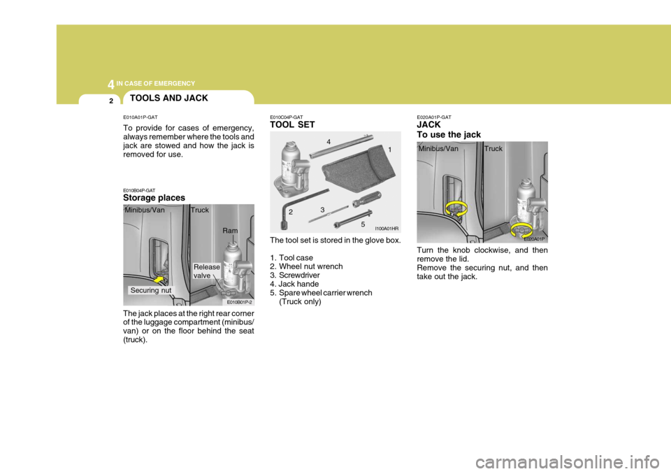
E010A01P-GAT To provide for cases of emergency, always remember where the tools and jack are stowed and how the jack is removed for use.
E010B04P-GAT Storage places E010C04P-GAT TOOL SET
E020A01P-GATJACK To use the jack
The jack places at the right rear corner of the luggage compartment (minibus/ van) or on the floor behind the seat(truck). Minibus/Van Truck
The tool set is stored in the glove box.
1. Tool case
2. Wheel nut wrench
3. Screwdriver4. Jack hande
5. Spare wheel carrier wrench(Truck only) Turn the knob clockwise, and then remove the lid. Remove the securing nut, and then take out the jack.
E010B01P-2 I100A01HR
E020A01P
Minibus/Van Truck
Securing nut
Ram 2
34
1
5
Page 181 of 284
4
CORROSION PREVENTION AND APPEARANCE CARE
5
4
IN CASE OF EMERGENCY
5
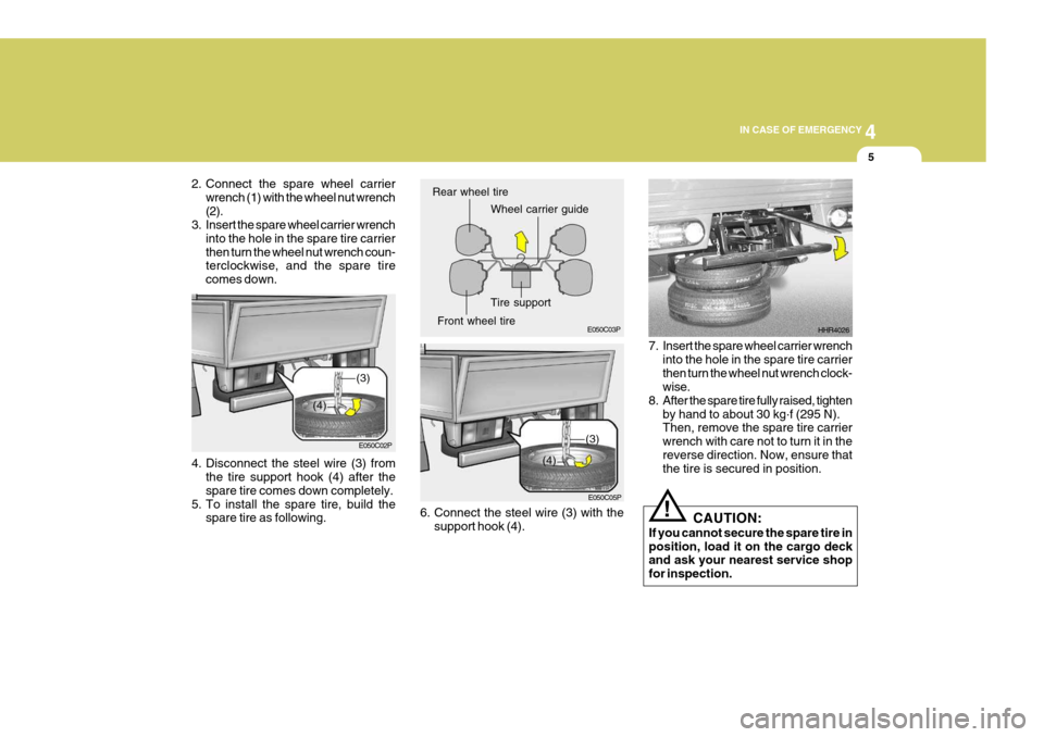
4. Disconnect the steel wire (3) from
the tire support hook (4) after the spare tire comes down completely.
5. To install the spare tire, build the spare tire as following. E050C02P
6. Connect the steel wire (3) with thesupport hook (4). 7. Insert the spare wheel carrier wrench
into the hole in the spare tire carrierthen turn the wheel nut wrench clock- wise.
8. After the spare tire fully raised, tighten
by hand to about 30 kg .
f (295 N).
Then, remove the spare tire carrier wrench with care not to turn it in thereverse direction. Now, ensure that the tire is secured in position. HHR4026
E050C03P
E050C05P
Rear wheel tire
Wheel carrier guide
Front wheel tire Tire support
(3)
(4)
(3)
(4)
CAUTION:
If you cannot secure the spare tire in position, load it on the cargo deck and ask your nearest service shop for inspection.!
2. Connect the spare wheel carrier
wrench (1) with the wheel nut wrench (2).
3. Insert the spare wheel carrier wrench
into the hole in the spare tire carrierthen turn the wheel nut wrench coun- terclockwise, and the spare tire comes down.
Page 184 of 284
44IN CASE OF EMERGENCY
8
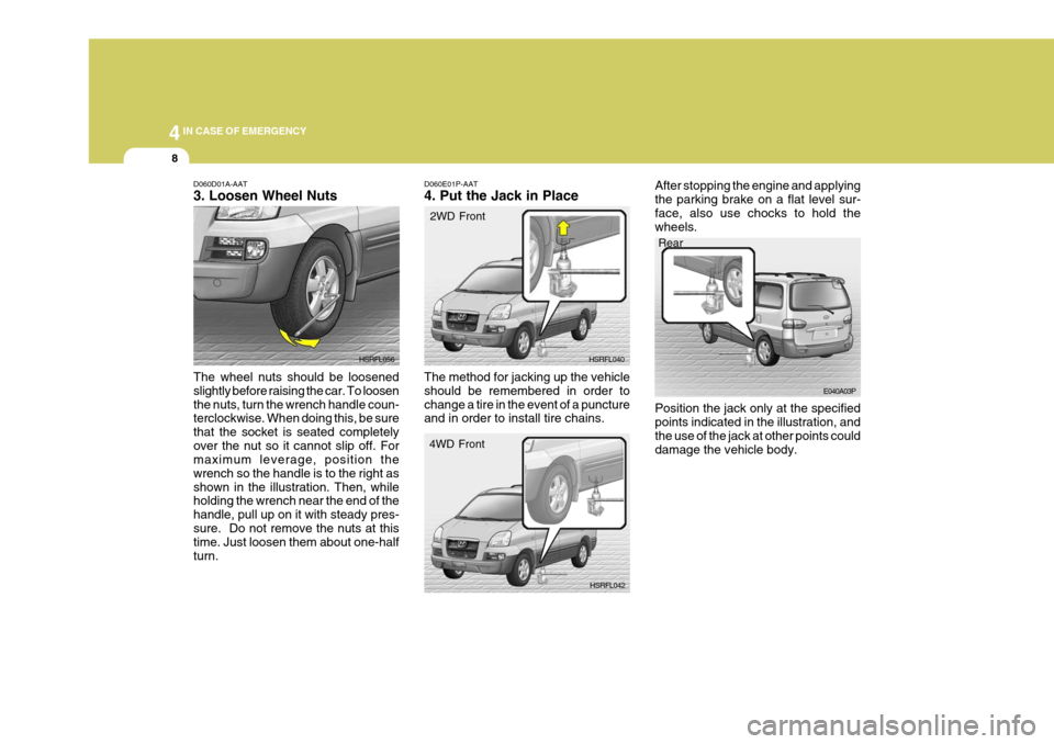
D060D01A-AAT 3. Loosen Wheel Nuts The wheel nuts should be loosened slightly before raising the car. To loosenthe nuts, turn the wrench handle coun- terclockwise. When doing this, be sure that the socket is seated completelyover the nut so it cannot slip off. For maximum leverage, position the wrench so the handle is to the right asshown in the illustration. Then, while holding the wrench near the end of the handle, pull up on it with steady pres-sure. Do not remove the nuts at this time. Just loosen them about one-half turn. HSRFL056
D060E01P-AAT 4. Put the Jack in Place
Rear
E040A03P
HSRFL040
HSRFL042
2WD Front
4WD Front
The method for jacking up the vehicle should be remembered in order tochange a tire in the event of a puncture and in order to install tire chains. After stopping the engine and applying the parking brake on a flat level sur-face, also use chocks to hold the wheels. Position the jack only at the specified points indicated in the illustration, and the use of the jack at other points coulddamage the vehicle body.
Page 185 of 284
4
CORROSION PREVENTION AND APPEARANCE CARE
9
4
IN CASE OF EMERGENCY
9
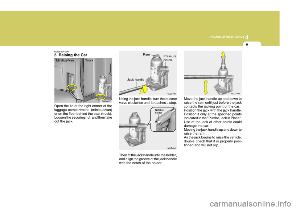
D060F02P-GAT 5. Raising the Car Open the lid at the right corner of the luggage compartment (minibus/van)or on the floor behind the seat (truck). Loosen the securing nut, and then take out the jack. Using the jack handle, turn the releasevalve clockwise until it reaches a stop.
HAUT408
HAUT405
E020A01P
Move the jack handle up and down to raise the ram until just before the jack contacts the jacking point of the car.Position the jack with the jack handle. Position it only at the specified points indicated in the "Put the Jack in Place".Use of the jack at other points could damage the car. Moving the jack handle up and down toraise the ram. As the jack begins to raise the vehicle, double check that it is properly posi-tioned and will not slip.
Then fit the jack handle into the holder,and align the groove of the jack handle with the notch of the holder.
Minibus/Van Truck
HAUT406RamPressure piston
Jack handle
Notch of holder