2007 Hyundai Getz steering wheel
[x] Cancel search: steering wheelPage 194 of 463

5- 10 VEHICLE MAINTENANCE REQUIREMENTS
F070L01A-AAT
o Suspension Mounting Bolts
Check the suspension connections for
looseness or damage. Retighten to the specified torque. F070M01A-AAT
o Steering Gear Box, Linkage &
Boots/Lower arm Ball Joint
With the vehicle stopped and engine
off, check for excessive free-play inthe steering wheel. Check the linkage for bends or damage. Check the dust boots and ball joints for deterioration,cracks, or damage. Replace any dam- aged parts.
F070N01A-AAT
o Power Steering Pump, Belt
and Hoses
Check the power steering pump and
hoses for leakage and damage. Re- place any damaged or leaking parts immediately. Inspect the power steer- ing belt for evidence of cuts, cracks,excessive wear, oiliness and proper tension. Replace or adjust it if neces- sary.
F070J01A-AAT
o Brake Pads, Calipers and
Rotors
Check the pads for excessive wear,
discs for run out and wear, and cali-pers for fluid leakage.
F070K01A-AAT
o Exhaust Pipe and Muffler
Visually inspect the exhaust pipes,
muffler and hangers for cracks, dete-rioration, or damage. Start the engineand listen carefully for any exhaust gas leakage. Tighten connections or replace parts as necessary.
F070F01A-AAT
o Brake Hoses and Lines Visually check for proper installation, chafing, cracks, deterioration and any leakage. Replace any deteriorated or damaged parts immediately. F070G02A-AAT
o Brake Fluid Check brake fluid level in the brake fluid reservoir. The level should be between "MIN" and "MAX" marks onthe side of the reservoir. Use only hydraulic brake fluid conforming to DOT 3 or DOT 4. F070H01A-AAT
o Rear Brake Drums/Linings
Parking Brake
Check the rear brake drums and lin- ings for scoring, burning, leaking fluid, broken parts, and excessive wear. Inspect the parking brake system in-cluding the parking brake lever and cables. For detailed service proce- dures, refer to the Shop Manual.
Page 200 of 463

DO-IT-YOURSELF MAINTENANCE 6- 5
G020A02A-AAT GENERAL CHECKS Engine Compartment The following should be checked regu-larly:
o Engine oil level and condition
o Transaxle fluid level and condition
o Brake fluid level
o Clutch fluid level
o Engine coolant level
o Windshield washer fluid level
o Accessory drive belt condition
o Engine coolant hose condition
o Fluid leaks (on or below compo-
nents)
o Power steering fluid level
o Battery condition
o Air filter condition G020C01A-AAT Vehicle Interior The following should be checked each time when the vehicle is driven:
o Lights operation
o Windshield wiper operation
o Horn operation
o Defroster, heater system operation
(and air conditioning, if installed)
o Steering operation and condition
o Mirror condition and operation
o Turn signal operation
o Accelerator pedal operation
o Brake operation, including parking brake
o Manual transaxle operation, includ- ing clutch operation
o Automatic transaxle operation, in- cluding "Park" mechanism opera-tion
o Seat control condition and opera- tion
o Seat belt condition and operation
o Sunvisor operation If you notice anything that does not operate correctly or appears to befunctioning incorrectly, inspect it care- fully and seek assistance from your Hyundai dealer if service is needed.
G020B01A-AAT Vehicle Exterior The following should be checked monthly:
o Overall appearance and condition
o Wheel condition and wheel nut
torgue
o Exhaust system condition
o Light condition and operation
o Windshield glass condition
o Wiper blade condition
o Paint condition and body corrosion
o Fluid leaks
o Door and hood lock condition
o Tire pressure and condition
(including spare tire)
Page 215 of 463

6- 20 DO-IT-YOURSELF MAINTENANCE
HTB293
4. Replace the two filters.
5. Installation is the reverse order of disassembly.
CAUTION:
Be sure to install the climate control air filter in the direction of the arrow sign. Unless, it may cause noise ordeterioration. G150A01A-GAT CHECKING STEERING WHEEL FREE-PLAY To check the steering wheel free-play, stop the car with the wheels pointed straight ahead and gently move thesteering wheel back and forth. Use very light finger pressure and be sen- sitive to changes in resistance thatmark the limits of the free-play. If the freeplay is greater than specified, have it inspected by your Hyundai dealerand adjusted or repaired if necessary.
G150A01TB
30 mm (1.18 in.)
!
HTB291
2. Remove the cable and the wiring from the filter cover.
HTB292
3. Remove the filter cover to push the upside of the filter cover.
Page 244 of 463

8- 6 CONSUMER INFORMATION
I100A01TB-GAT SPARE TIRE AND TOOLS
Your Hyundai is delivered with the fol- lowing: Spare tire and wheel Wheel nut wrench, Wrench bar, Screw driver,Jack, Towing hook HTB224
WARNING:
o Driving on worn-out tires is dan- gerous! Worn-out tires can cause
loss of braking effectiveness, steering control and traction. When replacing tires, never mixradial and bias-ply tires on the same car. If you replace radial tires with bias-ply tires, they mustbe installed in sets of four.
o Using tires and wheels of other
than the recommended sizes maycause unusual handling charac- teristics that may cause death, serious injury or property dam-age.
o Tires degrade over time, even when
they are not being used. Regard-less of the remaining tread, it is recommended that tires generally be replaced after six (6) years ofnormal service. Heat caused by hot climates or frequent high load- ing conditions can accelerate theaging process. Failure to follow this warning can result in sudden tire failure, which could lead to aloss of control and an accident involving serious injury or death.
!
The original tires on your car have tread wear indicators. The tread wear indica- tors appear when the tread depth is 1.6 mm (0.06 in.). The tire should be re-placed when these appear as a solid bar across two or more grooves of the tread. Always replace your tires withthose of the recommended size. If you change wheels, the new wheel's rim width and offset must meet Hyundaispecification.
I090A02S-GAT WHEN TO REPLACE TIRES
Wear indicator
1.6 mm (0.06 in.)
HGK248
Page 246 of 463

9- 2 VEHICLE SPECIFICATIONS
Type Wheel free playRack stroke Oil pump type 3,825 (150.6)
1,665(65.6) 1,495(58.9) 1,490(58.7)2,455(96.7) 1,450(57.1) 1,440(56.7)
Overall lengthOverall width Overall height (unladen)Wheel base Wheel tread J030A02TB-GAT TIREDual hydraulic with brake booster Ventilated disc DrumCable
J010A02TB-GAT MEASUREMENT
J060A01TB-GATFUEL SYSTEMRack and pinion 0 ~ 30 mm (0 ~ 1.18 in.) 140 mm (5.5 in.)132 mm (5.20 in.) Vane type
165/65R14, 175/65R14, 185/55R15
Option
Front Rear
mm (in.)
J020A01TB-GAT POWER STEERING
Fuel tank Capacity Capacity (Iceland only) Liter
4540 Imp.gal
9.98.8 J050A01FC-GAT BRAKE
Type Front brake type Rear brake type Parking brake
J035A01TB-GAT SPARE TIRE
T105/70D14(Temporary) Full size
Standard Option
GENEC
Manual Power
Page 253 of 463

INDEX 10- 5
Outside rear view mirror heater .................................. 1-75
P Parking Brake ............................................................. 1-76
Power outlet ................................................................ 1-67
Power Steering Fluid Level ......................................... 6-27
Power Windows .......................................................... 1-13
RRear ashtray ............................................................... 1-68
Rear Seat ................................................................... 1-17
Folding rear seatback and seat cushion ..................1-18
Rear Seat Entry .......................................................... 1-17
Rear seat warning ....................................................... 1-21
Rear Window Defroster Switch ................................... 1-65
SSeat Adjustable ................................................................ 1-13
Front ........................................................................ 1-13
Seatback Holder ......................................................... 1-79
Seat Pocket ................................................................ 1-79
Seat Warmer .............................................................. 1-20
Seat Belts
3-Point system ........................................................ 1-24
2-Point system ........................................................ 1-25
Adjustabl e height ..................................................... 1-23
Adjusting your seat belt ........................................... 1-25
Care of seat belts .................................................... 1-22
Precautions .............................................................. 1-21Smooth corneri
ng ........................................................ 2-16
Spectacle C ase .......................................................... 1-72
Speedometer .............................................................. 1-55
Starting ........................................................................ 2-5
Steering Wheel Freeplay ............................................. 6-20
Steering Wheel Tilt Lever ........................................... 1-83
Stereo Radio Operation (K220, K240, M280, H446) ..... 1-97, 1-102, 1-107, 1-118
Stereo Sound System ................................................ 1-95
Sun Visor .................................................................... 1-83
Sunroof ....................................................................... 1-69
Opening the sunroof ................................................ 1-69
Reseting the sunroof system ................................... 1-71
Tilting the sunroof .................................................... 1-70
T Tachometer ................................................................. 1-57
Tail gate ..................................................................... 1-78
Theft-Alarm system ..................................................... 1-9
Tires
Balancing .................................................................. 8-5
Chains ...................................................................... 8-4
If you have a flat tire ................................................ 3-6
Information ................................................................ 8-3
Pressure ................................................................... 8-3
Replacement ............................................................. 8-7
Rotation .................................................................... 8-5
Snow tires ................................................................ 8-4
Spare tire .................................................................. 3-5
Traction ..................................................................... 8-5
Page 300 of 463

1- 34 FEATURES OF YOUR HYUNDAI
HTB203
Rear impact
Side Impact Rollover
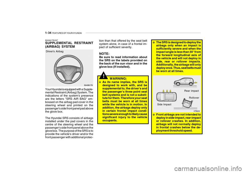
o The SRS is designed to deploy the
airbags only when an impact is sufficiently severe and when theimpact angle is less than 30° from the forward longitudinal axis of the vehicle and will not deploy inside, rear or rollover impacts. Additionally, the airbags will only deploy once. Thus, seat belts mustbe worn at all times.
o Front airbags are not intended to deploy in side-impact, rear-impactor rollover crashes. In addition, airbags will not normally deploy in frontal crashes below the de-ployment threshold speed.
!
B240B01TB
Driver's Airbag
Your Hyundai is equipped with a Supple- mental Restraint (Airbag) System. The indications of the system's presenceare the letters "SRS AIR BAG" em- bossed on the airbag pad cover in the steering wheel and printed on thepassenger's side front panel pad above the glove box. The Hyundai SRS consists of airbags installed under the pad covers in the centre of the steering wheel and thepassenger's side front panel above the glove box. The purpose of the SRS is to provide the vehicle's driver and/or thefront passenger with additional protec- B240A01TB-EAT SUPPLEMENTAL RESTRAINT (AIRBAG) SYSTEM
tion than that offered by the seat belt system alone, in case of a frontal im- pact of sufficient severity. NOTE: Be sure to read information about the SRS on the labels provided onthe back of the sun visor and in the glove box (If installed).
WARNING:
o As its name implies, the SRS is designed to work with, and besupplemental to, the driver's and the passenger's three point seatbelt systems and is not a substi- tute for them. Therefore your seat belts must be worn at all timeswhile the vehicle is in motion. In addition, the airbags deploy only in certain frontal impact condi-tions severe enough to likely cause significant injury to the vehicle occupants.
Page 302 of 463

1- 36 FEATURES OF YOUR HYUNDAI
B240B05L-D
Passenger's Airbag
!
CAUTION:
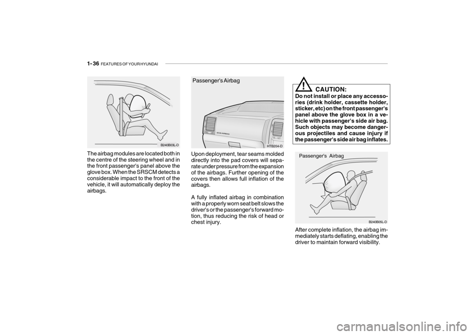
Do not install or place any accesso- ries (drink holder, cassette holder, sticker, etc) on the front passenger's panel above the glove box in a ve-hicle with passenger's side air bag. Such objects may become danger- ous projectiles and cause injury ifthe passenger's side air bag inflates. After complete inflation, the airbag im- mediately starts deflating, enabling the driver to maintain forward visibility.
B240B03L-D
The airbag modules are located both in the centre of the steering wheel and in the front passenger's panel above the glove box. When the SRSCM detects aconsiderable impact to the front of the vehicle, it will automatically deploy the airbags.
Passenger's Airbag
HTB204-D
Upon deployment, tear seams molded directly into the pad covers will sepa- rate under pressure from the expansion of the airbags. Further opening of thecovers then allows full inflation of the airbags. A fully inflated airbag in combination with a properly worn seat belt slows the driver's or the passenger's forward mo-tion, thus reducing the risk of head or chest injury.