2007 Hyundai Getz fuel cap
[x] Cancel search: fuel capPage 223 of 463

6- 28 DO-IT-YOURSELF MAINTENANCE
HTB287
G240A01A-AAT POWER STEERING HOSES It is suggested that you check the power steering hose connections forfluid leakage at regular intervals. The power steering hoses should be re- placed if there is severe surface crack-ing, scuffing or worn spots. Deteriora- tion of the hose could cause prema- ture failure.
G300A03TB-GAT REMOVAL OF WATER FROM THE FUEL FILTER(DIESEL ENGINE) If the fuel filter warning light illuminates during driving, it indicates that water has accumulated in the fuel filter. NOTE: It is recommended that water accu- mulated in the fuel filter should be removed by an authorized Hyundai dealer. WARNING:
Be sure to carefully wipe away anywater drained out in this manner,because the fuel mixed in the water might be ignited and result in a fire.
!
Extracting air in the fuel filter If you drove until you have no fuel left or if you replaced the fuel filter, be sure to extract air in the fuel system as itmakes you difficult to start the engine.
1) Remove the air extract nozzle cap on the fuel filter.
2) Pump up and down until the fuel flows out of the plug opening.
NOTE: Use cloths when you extract air so that the fuel is not sprayed around. Clean the fuel around the fuel filter orthe injection pump before starting the engine to prevent fire. Finally, check each part if the fuel is leaking.
Page 236 of 463

7- 2 EMISSION CONTROL SYSTEMS
H010A01A-GAT
EMISSION CONTROL SYSTEM (If Installed)
Your Hyundai is equipped with an
emission control system to meet all requirements of the Emission prohibi- tion rules of your province.
There are three emission control sys-
tems which are as follows.
1) Crankcase emission control sys-
tem
2) Evaporative emission control sys- tem
3) Exhaust emission control system
In order to assure the proper function
of the emission control systems, it is recommended that you have your carinspected and maintained by an au- thorized Hyundai dealer in accordance with the maintenance schedule in thismanual. H010B01A-AAT
1. Crankcase Emission Control
System
The positive crankcase ventilation
system is employed to prevent airpollution caused by blow-by gases being emitted from the crankcase. This system supplies fresh air to thecrankcase through the air intake hose. Inside the crankcase, the fresh air mixes with blow-by gases, which thenpass through the PCV valve and into the induction system.
H010C02E-GAT
2. Evaporative Emission Control
System
The Evaporative Emission Control
System is designed to prevent fuel vapors from escaping into the atmo-sphere. Canister
While the engine is inoperative, fuel
vapors generated inside the fuel tank are absorbed and stored in the canis- ter. When the engine is running, the fuel vapors absorbed in the canister are drawn into the induction system through the purge control solenoid valve. Purge Control Solenoid Valve (PCSV)
The purge control solenoid valve is
controlled by the Engine Control Mod- ule (ECM); when the engine coolanttemperature is low during idling, the PCSV closes so that evaporated fuel is not taken into the engine. After theengine warms-up during ordinary driv- ing, the PCSV opens so as to intro- duce evaporated fuel to the engine. H010D01A-AAT
3. Exhaust Emission Control
System
The exhaust emission control system is a highly effective system whichcontrols exhaust emission while main- taining good vehicle performance.
TBENG_7.P65 6/14/2005, 3:31 PM
2
Page 246 of 463

9- 2 VEHICLE SPECIFICATIONS
Type Wheel free playRack stroke Oil pump type 3,825 (150.6)
1,665(65.6) 1,495(58.9) 1,490(58.7)2,455(96.7) 1,450(57.1) 1,440(56.7)
Overall lengthOverall width Overall height (unladen)Wheel base Wheel tread J030A02TB-GAT TIREDual hydraulic with brake booster Ventilated disc DrumCable
J010A02TB-GAT MEASUREMENT
J060A01TB-GATFUEL SYSTEMRack and pinion 0 ~ 30 mm (0 ~ 1.18 in.) 140 mm (5.5 in.)132 mm (5.20 in.) Vane type
165/65R14, 175/65R14, 185/55R15
Option
Front Rear
mm (in.)
J020A01TB-GAT POWER STEERING
Fuel tank Capacity Capacity (Iceland only) Liter
4540 Imp.gal
9.98.8 J050A01FC-GAT BRAKE
Type Front brake type Rear brake type Parking brake
J035A01TB-GAT SPARE TIRE
T105/70D14(Temporary) Full size
Standard Option
GENEC
Manual Power
Page 251 of 463

INDEX 10- 3
D Day/Night inside rearview mirror ................................. 1-76
Defrosting / Defogging ................................................ 1-91
Digital clock ................................................................ 1-66
Door Door locks ................................................................ 1-7 Locking, unlocking front doors with a key ................ 1-7
Locking from the inside ............................................ 1-8
Locking from the outside .......................................... 1-8
Drink Holder ................................................................ 1-68
Drive Belts .................................................................. 6-22
Driving
Economical driving .................................................. 2-15
Smooth corneri ng ..................................................... 2-16
Winter driving ........................................................... 2-16
E Electronic stability program (ESP) ..............................2-14
Emission Contro l System ............................................ 7-2
Engine
Before starting the engine ........................................ 2-3Compartment ............................................................ 6-2
Coolant .................................................................... 6-10
Coolant temperature gauge ......................................1-54
If the engine overheats ............................................. 3-4
Number ..................................................................... 8-2
Oil ............................................................................. 6-7Starting ..................................................................... 2-3
Engine Exhaust Can Be Dangerous ............................ 2-2 FFog Light
Front ........................................................................ 1-65
Rear ......................................................................... 1-66
Folding the outside rearview mirror .............................1-75
Front Seats
Adjustable front seats .............................................. 1-13
Adjustable headrests ............................................... 1-14
Adjusting seat forward and rearward ........................1-13
Adjusting seatback angle .. ......................................1-13
Lumbar support control ............................................ 1-15
Seat cushion height adjustment .............................. 1-16
Seat warmer ............................................................ 1-20
Fuel
Capacity ................................................................... 9-2
Gauge ...................................................................... 1-55
recommendations ...................................................... 1-2
Fuel Filler Lid
Remote release ....................................................... 1-78
Fuses ......................................................................... 6-23
Fuse Panel description ............................................... 6-36
GGeneral Checks ........................................................... 6-5
Glove Box .................................................................. 1-73
Page 318 of 463

1- 52 FEATURES OF YOUR HYUNDAI
If the red indicator illuminates, pull over and stop as soon as possible and turn off the engine. Then open the bonnetand check the coolant level (See "If the engine overheats" on the page 3-4.) and the water pump drive belt. If you sus-pect cooling system trouble, have your cooling system checked by a Hyundai dealer as soon as possible. NOTE: If the red engine temperature indica- tor illuminates, it indicates overheat-ing that may damage the engine.
B265A01FC-EAT
FUEL FILTER WARNING LIGHT-RED(Diesel Engine)
This light illuminates when the engine has started and go off after a approimately seconds. If it lights upwhile the engine is running, it indicates that water has accumulated inside the fuel filter. If this happens, remove thewater from the fuel filter. (Refer to "6-24 page")B290A01TB-EAT ENGINE COOLANT TEM-
PERATURE INDICATOR
WARNING:
Never remove the radiator cap when the engine is hot. The engine coolantis under pressure and could erupt and cause severe burns. Wait until the engine is cool before removingthe radiator cap.
!
These indicators show the temperature of the engine coolant when the ignition switch is ON. Red indicator illuminatesif the temperature of the engine coolant is above 120±3°C (248±37.4°F). Blue indicator Illuminates if the tem-perature of the engine coolant is below 60±3°C (140±37.4°F).
Page 319 of 463

FEATURES OF YOUR HYUNDAI 1- 53
B300A01A-EAT SPEEDOMETER
B300A01TB-E
Your Hyundai's speedometer is cali- brated in miles per hour or kilometers per hour.
A Type B Type
SB210S1-E BRAKE PAD WEAR INDICATOR The front brake disc pads are fitted with an audible wear indicator which will cause a high pitched noise to be emit- ted when the remaining amount of fric-tion lining is below the specified value. When the wear indicator is heard, the brake pads should be replaced withoutdelay to avoid damage occurring to the brake discs and a severe reduction in braking efficiency.
B900A01A-EAT ACOUSTIC WARNING SOUND (Not all models) The acoustic warning chime sounds when the tail lights are on and the door in driver side is open. This prevents thebattery from discharging when the car is left with the tail lights on. The chime sounds until the tail lights are turned off.
The needle on the gauge indicates the approximate fuel level in the fuel tank.The fuel capacity is given in Section 9.
B280A01A-AAT FUEL GAUGE
HTB2019
Page 341 of 463

FEATURES OF YOUR HYUNDAI 1- 75
NOTE: If the fuel-filler flap will not open because ice has formed around it, tap lightly or push on the lid to breakthe ice and release the lid. Do not lever the flap. If necessary, spray around the flap with an approved de-icer fluid (do not use radiator anti- freeze) or move the vehicle to a warm place and allow the ice to melt.
HTB068
!WARNING:
o Gasoline vapors are dangerous. Before refueling, always stop the engine and never allow sparks or open flames near the filler area. Ifyou need to replace the filler cap, use a genuine Hyundai replace- ment part.If you open the fuel filler cap dur- ing high ambient temperatures, a slight "pressure sound" may beheard. This is normal and not a cause for concern. Whenever you open the fuel fillercap, turn it slowly.
o Automotive fuels are flammable/
explosive materials. When refuel-ing, please note the following guidelines carefully.
o Before touching the fuel nozzle or
fuel filler cap, have one's hands incontact with metal parts away from the filler neck to discharge staticelectricity.
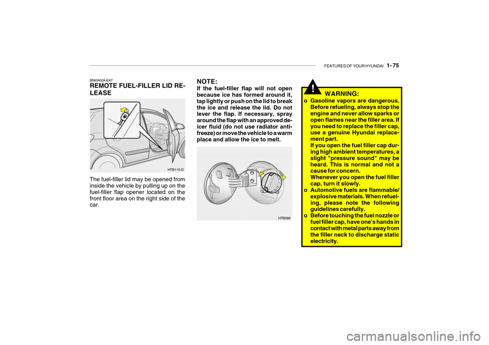
B560A02A-EAT REMOTE FUEL-FILLER LID RE- LEASE
The fuel-filler lid may be opened from inside the vehicle by pulling up on the fuel-filler flap opener located on thefront floor area on the right side of the car. HTB115-D
Page 342 of 463

1- 76 FEATURES OF YOUR HYUNDAI
B540A01FC-EAT HATCHBACK DOOR
HTB067
WARNING:
The hatchback door should always be kept completely closed while the vehicle is in motion. If it is left openor ajar, poisonous exhaust gases may enter the car resulting in seri- ous illness or death to the occu-pants. See additional warnings con- cerning exhaust gases on page 2-2.
!
o The hatchback door can be locked or unlocked with a key.
o The hatchback door is opened by pulling the outside handle up, raising the hatchback door manually.
o To close, lower the hatchback door, then press down on it until it isclosed. To be sure the hatchback door is fully closed, always try to pullit up again without using the outside handle.o Do not get back in the vehicle
while refueling. Do not operate anything that can produce static electricity. Static electricity dis-charge can ignite fuel vapors re- sulting in explosion.
o When using a portable fuel con-
tainer be sure to place the con-tainer on the ground while refuel- ing. Static electricity dischargefrom the container can ignite fuel vapors causing a fire. While start- ing refueling contact should bemaintained until the filling is com- plete.
o Do not use cellular phones around a gas station. The electric current or electronic interference fromcellular phones can ignite fuel vapors causing a fire.
o When refueling always shut the
engine off. Sparks by electricalequipment of the engine can ig- nite fuel vapors causing a fire.After refueling, check to make sure the fuel filler cap is securely closed, and then start the engine.
o Do not smoke or try to light ciga- rettes around a gas station. Auto-motive fuels are flammable.