2007 Hyundai Accent headlights
[x] Cancel search: headlightsPage 71 of 282

1
FEATURES OF YOUR HYUNDAI
59
B260F01A-AAT High Beam Indicator Light
The high beam indicator light comes on whenever the headlights are switched to the high beam or flash position.
B260D01A-AAT Turn Signal Indicator Lights
The blinking green arrows on the instru- ment panel show the direction indicated by the turn signals. If the arrow comeson but does not blink, blinks more rapidly than normal, or does not illumi- nate at all, a malfunction in the turnsignal system is indicated. Your dealer should be consulted for repairs.
!
B260P02Y-GAT ABS Service Reminder Indicator (SRI) Light(If Installed)
When the key is turned to the "ON" position, the Anti-Lock Brake System SRI will come on and then go off in a fewseconds. If the ABS SRI remains on, comes on while driving, or does not come on when the key is turned to the"ON" position, this indicates that there may be a problem with the ABS. If this occurs, have your vehiclechecked by your Hyundai dealer as soon as possible. The normal braking system will still be operational, butwithout the assistance of the anti-lock brake system. B260C01A-AAT
O/D OFF Indicator (Automatic transaxleonly)
When the overdrive switch is turned on, the overdrive off indicator will go out. This amber indicator will be illuminatedwhen the overdrive switch is turned off. WARNING:
If both ABS SRI and Parking Brake/Brake fluid level warning lights re- main "ON" or come on while driving, there may be a problem with E.B.D(Electronic Brake Force Distribution). If this occurs, avoid sudden stops and have your vehicle checked byyour Hyundai dealer as soon as pos- sible.
Page 84 of 282

1FEATURES OF YOUR HYUNDAI
72
B340A01A-AAT Combination Turn Signal, Head- light And High-beam SwitchTurn Signal Operation Pulling down on the lever causes the turn signals on the left side of the car to blink. Pushing upwards on the levercauses the turn signals on the right side of the car to blink. As the turn is com- pleted, the lever will automatically re-turn to the center position and turn off the turn signals at the same time. If either turn signal indicator light blinksmore rapidly than usual, goes on but does not blink, or does not go on at all, there is a malfunction in the system.Check for a burned-out fuse or bulb or see your Hyundai dealer. B340B01A-AAT Lane Change Signal To indicate a lane change, move the lever up or down to a point where it begins flashing.The lever will automatically return to the center position when released.
B340B01MC
B340C04FC-GAT Headlight Switch
To operate the headlights, turn the bar- rel on the end of the multi-function switch. The first position turns on theparking lights, sidelights, tail lights and instrument panel lights. The second position turns on the headlights. NOTE: The ignition must be in the "ON" position to turn on the headlights. Parking Light Auto Cut
o The purpose of this feature is to prevent the battery from being dis- charged.B340C02MC
MULTI-FUNCTION LIGHT SWITCH
Page 85 of 282

1
FEATURES OF YOUR HYUNDAI
73
B340E01A-AAT Headlight Flasher
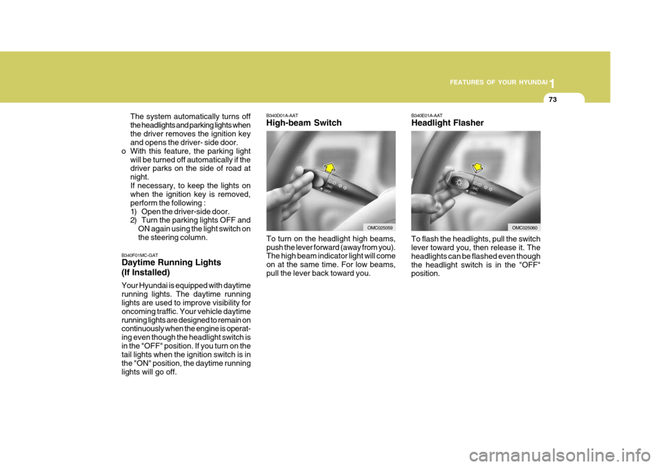
To flash the headlights, pull the switch lever toward you, then release it. The headlights can be flashed even thoughthe headlight switch is in the "OFF" position.
B340D01A-AAT High-beam Switch
B340F01MC-GAT Daytime Running Lights (If Installed) Your Hyundai is equipped with daytime running lights. The daytime running lights are used to improve visibility for oncoming traffic. Your vehicle daytimerunning lights are designed to remain on continuously when the engine is operat- ing even though the headlight switch isin the "OFF" position. If you turn on the tail lights when the ignition switch is in the "ON" position, the daytime runninglights will go off. The system automatically turns offthe headlights and parking lights whenthe driver removes the ignition key and opens the driver- side door.
o With this feature, the parking light
will be turned off automatically if thedriver parks on the side of road at night.If necessary, to keep the lights on when the ignition key is removed, perform the following :
1) Open the driver-side door.
2) Turn the parking lights OFF andON again using the light switch on the steering column.
OMC025060
To turn on the headlight high beams, push the lever forward (away from you). The high beam indicator light will come on at the same time. For low beams,pull the lever back toward you.OMC025059
Page 101 of 282

1
FEATURES OF YOUR HYUNDAI
89PARKING BRAKE
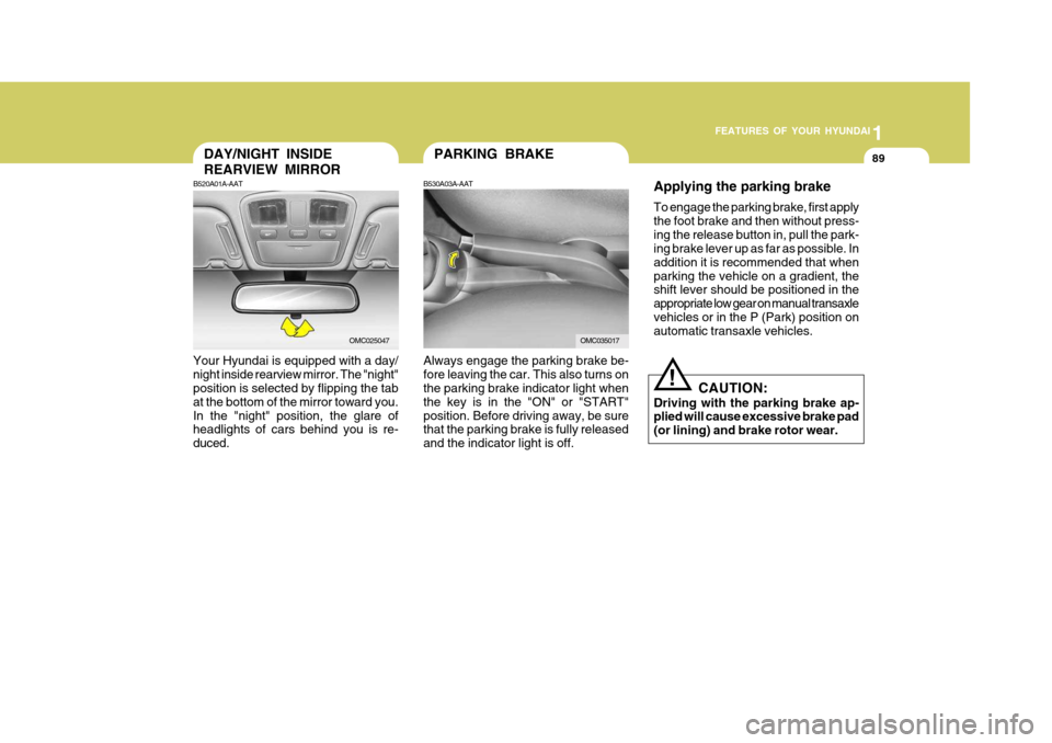
Always engage the parking brake be- fore leaving the car. This also turns on the parking brake indicator light when the key is in the "ON" or "START"position. Before driving away, be sure that the parking brake is fully released and the indicator light is off.
B530A03A-AATDAY/NIGHT INSIDE REARVIEW MIRROR
B520A01A-AAT
Your Hyundai is equipped with a day/ night inside rearview mirror. The "night" position is selected by flipping the tab at the bottom of the mirror toward you.In the "night" position, the glare of headlights of cars behind you is re- duced.
OMC025047OMC035017 Applying the parking brake To engage the parking brake, first apply the foot brake and then without press-ing the release button in, pull the park-
ing brake lever up as far as possible. In addition it is recommended that whenparking the vehicle on a gradient, the shift lever should be positioned in the appropriate low gear on manual transaxlevehicles or in the P (Park) position on automatic transaxle vehicles.
CAUTION:
Driving with the parking brake ap-plied will cause excessive brake pad (or lining) and brake rotor wear.
!
Page 185 of 282

2 DRIVING YOUR HYUNDAI
22HIGHER SPEED MOTORING
C160K01A-AAT Carry Emergency Equipment Depending on the severity of the weather where you drive your car, you should carry appropriate emergencyequipment. Some of the items you may want to carry include tire chains, tow straps or chains, flashlight, emer-gency flares, sand, a shovel, jumper cables, a window scraper, gloves, ground cloth, coveralls, a blanket, etc.
C160J01A-AAT Don't Let Ice and Snow Accumu- late Underneath Under some conditions, snow and ice can build up under the fenders andinterfere with the steering. When driv- ing in severe winter conditions where this may happen, you should periodi-cally check underneath the car to be sure the movement of the front wheels and the steering components is notobstructed.
C170A01A-AAT Pre-Trip Inspections 1. Tires: Adjust the tire inflation pressures to specification. Low tire inflation pres-sures will result in overheating and possible failure of the tires. Avoid using worn or damaged tireswhich may result in reduced traction or tire failure. NOTE: Never exceed the maximum tire in- flation pressure shown on the tires.
2. Fuel, engine coolant and
engine oil:
High speed travel consumes more fuel than urban motoring. Do not forget tocheck both engine coolant and engine oil. 3. Drive belt: A loose or damaged drive belt may result in overheating of the engine.USE OF LIGHTS
C180A01A-AAT Check your lights regularly for correct operation and always keep them clean. When driving during the day in condi- tions of poor visibility, it is helpful todrive with headlights on low beam. This enables you to be seen as well as to see.
Page 245 of 282

6 DO-IT-YOURSELF MAINTENANCE
22
!
CHECKING THE BATTERY
G210A01A-AAT
WARNING:
Batteries can be dangerous! When working with batteries, carefully ob-serve the following precautions to avoid serious injuries. The fluid in the battery contains a strong solution of sulfuric acid, which is poi- sonous and highly corrosive. Be careful not to spill it on yourself or the car. If youdo spill battery fluid on yourself, imme- diately do the following:
OMC055018
G200C01CM-GAT Power Connector
NOTE:
o If the power connector is pulled
up from the fuse panel, the warn- ing chime, audio, clock and inte- rior lamps, etc., will not operate. The following items must be resetafter replacement. - Digital Clock - Trip computer
- Automatic heating and cooling control system
- Audio
o Even though the power connector is pulled up, the battery can stillbe discharged by operation of theheadlights or other electrical de- vices.
Your vehicle is equipped with a power connector to prevent battery discharge if your vehicle is parked without being operated for prolonged periods. Use thefollowing procedures before parking the vehicle for prolonged periods.
1. Turn off the engine.
2. Turn off the headlights and tail lights.
3. Open the driver’s side panel cover
and pull up the power connector.
4. Insert the power connector in the
opposite direction.
G200F01MC
Page 249 of 282

6 DO-IT-YOURSELF MAINTENANCE
26HEADLIGHT AIMING ADJUSTMENT
5. Open the hood.
6. Draw the vertical line (through the
center of each headlight beam pat-tern) and the horizontal line (throughthe center of each headlight beam pattern) on the aiming screen. And then, draw a horizontal parallel line at 30 mm (1.18 in.) under the horizontal line.
7. Adjust each cut-off line of the low beam to the parallel line with a phillipsscrewdriver - VERTICAL AIMING.
8. Adjust each cut-off line of the low
beam to each vertical line with aphillips screwdriver - HORIZONTAL AIMING. Horizontal aiming
Vertical aiming
If the vehicle has had front body repair and the headlight assembly has beenreplaced, an headlight aiming should be checked using an aiming screen as shown in the illustration. Turn on theheadlight switch. (Low Beam Position)
1. Adjust headlights so that main axisof light is parallel to center line of the body and is aligned with point "P" shown in the illustration.
2. Dotted lines in the illustration show the center of headlights.
G290B01MC-GAT Adjustment After Headlight As- sembly Replacement
G290A03A-GAT Before performing aiming adjustment, make sure of the following.
1. Keep all tires inflated to the correct
pressure.
2. Place the vehicle on level ground
and press the front bumper and rear bumper down several times. Place the vehicle at a distance of 3,000 mm (118 in.) from the test wall.
3. See that the vehicle is unloaded (except for full levels of coolant,engine oil and fuel, and spare tire,jack, and tools). Have the driver or equivalent weight placed in driver's seat.
4. Clean the head lights lenses and turn on the headlight (low beam). G290B01B
LW
H
H Cut-off line
Ground line
"P"
Horizontal line
Vertical line30 mm
G290A03MC
Page 250 of 282

6
DO-IT-YOURSELF MAINTENANCE
27REPLACEMENT OF LIGHT BULBS
SPECIFICATIONS: "H" Horizontal center line of headlights from ground.: 665 mm (26.18 in.) "W" Distance between each headlight center. : 1,170 mm (46.06 in.) "L" Distance between the headlightsand the wall that the lights are tested against. : 3,000 mm (118.11 in.). G260A01MC-AAT Before attempting to replace a light bulb, be sure the switch is turned to the "OFF" position.The next paragraph shows how to reach the light bulbs so they may be changed. Be sure to replace the burned-out bulbwith one of the same number and watt- age rating. See page 6-34 for the wattage descrip-tions.
CAUTION:
o Keep the lamps out of contact with petroleum products, such as oil,gasoline, etc.
o If you don't have necessary tools,
the correct bulbs and the exper-tise, consult your authorized Hyundai dealer.
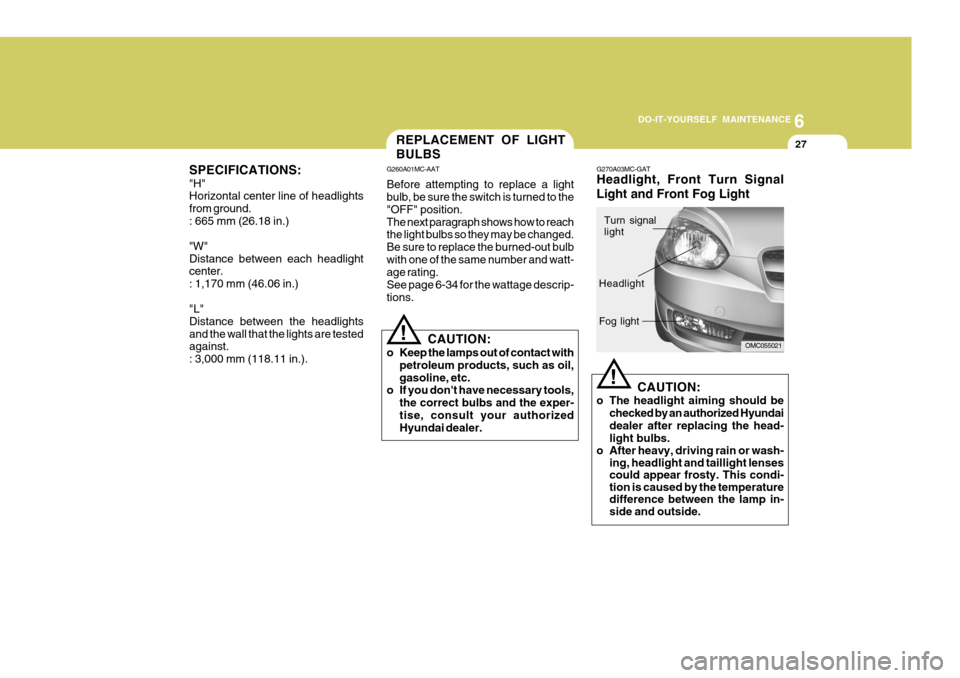
! G270A03MC-GAT Headlight, Front Turn Signal Light and Front Fog Light
CAUTION:
o The headlight aiming should be checked by an authorized Hyundai dealer after replacing the head- light bulbs.
o After heavy, driving rain or wash- ing, headlight and taillight lenses could appear frosty. This condi-tion is caused by the temperaturedifference between the lamp in-side and outside.
!
OMC055021
Turn signal light
Headlight Fog light